steering Ram 4500 Chassis Cab 2018 Owner's Manual
[x] Cancel search | Manufacturer: RAM, Model Year: 2018, Model line: 4500 Chassis Cab, Model: Ram 4500 Chassis Cab 2018Pages: 298, PDF Size: 5.88 MB
Page 135 of 298

the front and rear wheels to rotate at the same
speed. This range provides additional trac-
tion and maximum pulling power for loose,
slippery road surfaces only. Do not exceed
25 mph (40 km/h).
NEUTRAL (N)
Neutral — This range disengages both the
front and rear driveshafts from the pow-
ertrain. To be used for flat towing behind
another vehicle. Refer to “Recreational Tow-
ing” in this section for further information.
WARNING!
You or others could be injured or killed if
you leave the vehicle unattended with the
transfer case in the NEUTRAL position
without first fully engaging the parking
brake. The transfer case NEUTRAL posi-
tion disengages both the front and rear
drive shafts from the powertrain and will
allow the vehicle to roll, even if the trans-
mission is in PARK. The parking brake
should always be applied when the driver
is not in the vehicle.This electronically shifted transfer case is
designed to be driven in the two-wheel drive
position (2WD) for normal street and highway
conditions on dry, hard surfaced roads.
When additional traction is required, the
transfer case 4WD LOCK and 4WD LOW po-
sitions can be used to maximize torque to the
front driveshaft, forcing the front and rear
wheels to rotate at the same speed. This is
accomplished by rotating the 4WD Control
Switch to the desired position.
Refer to “Shifting Procedure” in the “Start-
ing And Operating” section of your Owner’s
Manual
locatedat
www.mopar.com/en-us/care/owners-manual.html
(U.S. Residents) or www.owners.mopar.ca
(Canadian Residents) for specific shifting in-
structions.
SPEED CONTROL
When engaged, the Speed Control takes over
accelerator operations at speeds greater than
25 mph (40 km/h). The Speed Control buttons are located on the
right side of the steering wheel.
Speed Control Buttons
1 — Push Cancel
2 — Push On/Off
3 — Push Resume/Accel
4 — Push Set/Decel
133
Page 139 of 298

the forward vehicle speed exceeds 8 mph
(13 km/h), the transmission is shifted into
PARK or the ignition is switched to the OFF
position.
Whenever the Rear View Camera image is
activated through the "Backup Camera" but-
ton in the "Controls" menu, a display timer for
the image is initiated. The image will con-
tinue to be displayed until the display timer
exceeds 10 seconds and the vehicle speed is
above 8 mph (13 km/h) or the touchscreen
button "X" to disable display of the Rear View
Camera image is pressed.
NOTE:
If the vehicle speed remains below 8 mph
(13 km/h), the Rear View Camera image will
be displayed continuously until deactivated
via the touchscreen button "X".
If equipped with a Cargo Camera, a touch-
screen button
to indicate the current
active Camera image being displayed is made
available whenever the Rear View Camera
image is displayed. If equipped with a Cargo Camera, a touch-
screen button
to switch the display to
Cargo Camera image is made available when-
ever the Rear View Camera image is dis-
played.
A touchscreen button "X" to disable display of
the camera image is made available when the
vehicle is not in REVERSE gear.
When enabled, active guide lines are overlaid
on the image to illustrate the width of the
vehicle and its projected backup path based
on the steering wheel position. The active
guide lines will show separate zones that will
help indicate the distance to the rear of the
vehicle.
NOTE:
For further information about how to access
and change the programmable features of the
ParkView Rear Backup Camera, refer to
“Uconnect Settings ” in “Multimedia” in the
Owner’s Manual at www.mopar.com/en-us/
care/owners-manual.html (U.S. Residents) or
www.owners.mopar.ca (Canadian Residents)
for further information.WARNING!
Drivers must be careful when backing up
even when using the ParkView Rear Back
Up Camera. Always check carefully behind
your vehicle, and be sure to check for
pedestrians, animals, other vehicles, ob-
structions, or blind spots before backing
up. You are responsible for the safety of
your surroundings and must continue to
pay attention while backing up. Failure to
do so can result in serious injury or death.
CAUTION!
• To avoid vehicle damage, ParkView should only be used as a parking aid.
The ParkView camera is unable to view
every obstacle or object in your drive
path.
• To avoid vehicle damage, the vehicle
must be driven slowly when using
ParkView to be able to stop in time when
an obstacle is seen. It is recommended
that the driver look frequently over his/
her shoulder when using ParkView.
137
Page 145 of 298

CAUTION!
• Then, during the first 500 miles(805 km) that a trailer is towed, do not
drive over 50 mph (80 km/h) and do not
make starts at full throttle. This helps
the engine and other parts of the vehicle
wear in at the heavier loads.
Perform the maintenance listed in the
“Scheduled Servicing”. Refer to “Scheduled
Servicing” in “Servicing And Maintenance”
for the proper maintenance intervals. When
towing a trailer, never exceed the GAWR or
GCWR ratings.
WARNING!
Improper towing can lead to a collision.
Follow these guidelines to make your
trailer towing as safe as possible:
• Make certain that the load is secured in the trailer and will not shift during travel.
When trailering cargo that is not fully
secured, dynamic load shifts can occur
that may be difficult for the driver to
WARNING!
control. You could lose control of your
vehicle and have a collision.
• When hauling cargo or towing a trailer,
do not overload your vehicle or trailer.
Overloading can cause a loss of control,
poor performance or damage to brakes,
axle, engine, transmission, steering,
suspension, chassis structure or tires.
• Safety chains must always be used be-
tween your vehicle and trailer. Always
connect the chains to the hook retainers
of the vehicle hitch. Cross the chains
under the trailer tongue and allow
enough slack for turning corners.
• Vehicles with trailers should not be
parked on a grade. When parking, apply
the parking brake on the tow vehicle. Put
the tow vehicle transmission in PARK.
For four-wheel drive vehicles, make sure
the transfer case is not in NEUTRAL.
Always, block or "chock" the trailer
wheels.
• GCWR must not be exceeded.
WARNING!
• Total weight must be distributed between
the tow vehicle and the trailer such that the
following four ratings are not exceeded:
1. GVWR
2. GTW
3. GAWR
4. Tongue weight rating for the trailer hitch utilized.
Towing Requirements — Trailer Brakes
•Do notinterconnect the hydraulic brake
system or vacuum system of your vehicle
with that of the trailer. This could cause
inadequate braking and possible personal
injury.
• An electronically actuated trailer brake controller is required when towing a trailer
with electronically actuated brakes. When
towing a trailer equipped with a hydraulic
surge actuated brake system, an electronic
brake controller is not required.
143
Page 147 of 298

GAIN Adjustment Buttons (+/-)
Pushing these buttons will adjust the brake
control power output to the trailer brakes in
0.5 increments. The GAIN setting can be
increased to a maximum of 10 or decreased
to a minimum of 0 (no trailer braking).
GAIN
The GAIN setting is used to set the trailer
brake control for the specific towing condi-
tion and should be changed as towing condi-
tions change. Changes to towing conditions
include trailer load, vehicle load, road condi-
tions and weather.
Adjusting GAIN
NOTE:
This should only be performed in a traffic free
environment at speeds of approximately 20–
25 mph (30–40 km/h).
1. Make sure the trailer brakes are in goodworking condition, functioning normally
and properly adjusted. See your trailer
dealer if necessary. 2. Hook up the trailer and make the electri-
cal connections according to the trailer
manufacturer's instructions.
3. When a trailer with electric/EOH brakes is plugged in, the trailer connected message
should appear in the instrument cluster
display (if the connection is not recog-
nized by the ITBM, braking functions will
not be available), the GAIN setting will
illuminate and the correct type of trailer
must be selected from the instrument
cluster display options.
4. Push the UP or DOWN button on the steering wheel until “TRAILER TOW” ap-
pears on the screen.
5. Push the RIGHT arrow on the steering wheel to enter “TRAILER TOW”.
6. Push the UP or DOWN buttons until the Trailer Brake Type appears on the screen. 7. Push the RIGHT arrow and then push the
UP or DOWN buttons until the proper
Trailer Brake Type appears on the screen.
8. In a traffic-free environment, tow the trailer on a dry, level surface at a speed of
20–25 mph (30–40 km/h) and squeeze
the manual brake control lever
completely.
9. If the trailer wheels lockup (indicated by squealing tires), reduce the GAIN setting;
if the trailer wheels turn freely, increase
the GAIN setting.
Repeat steps 8 and 9 until the GAIN setting
is at a point just below trailer wheel lockup. If
towing a heavier trailer, trailer wheel lockup
may not be attainable even with the maxi-
mum GAIN setting of 10.
145
Page 157 of 298

FUSES
WARNING!
• When replacing a blown fuse, always usean appropriate replacement fuse with
the same amp rating as the original fuse.
Never replace a fuse with another fuse of
higher amp rating. Never replace a
blown fuse with metal wires or any other
material. Do not place a fuse inside a
circuit breaker cavity or vice versa. Fail-
ure to use proper fuses may result in
serious personal injury, fire and/or prop-
erty damage.
WARNING!
• Before replacing a fuse, make sure thatthe ignition is off and that all the other
services are switched off and/or disen-
gaged.
• If the replaced fuse blows again, contact
an authorized dealer.
• If a general protection fuse for safety
systems (air bag system, braking sys-
tem), power unit systems (engine sys-
tem, transmission system) or steering
system blows, contact an authorized
dealer.
Power Distribution Center
The Power Distribution Center is located in
the engine compartment near the battery.
This center contains cartridge fuses, micro
fuses, relays, and circuit breakers. A descrip-
tion of each fuse and component may be
stamped on the inside cover, otherwise the
cavity number of each fuse is stamped on the
inside cover that corresponds to the following
chart.
Cavity Cartridge Fuse Micro Fuse Description
F01 80 Amp Black –Rad Fan Control Module – If Equipped
F03 60 Amp Yellow –Rad Fan – If Equipped
F05 40 Amp Green –Compressor for Air Suspension – If Equipped
F06 40 Amp Green –Antilock Brakes/Electronic Stability Control Pump
F07 40 Amp Green – Starter Solenoid
F08 20 Amp Blue (1500 LD/
Cummins Diesel) –
Emissions Diesel – If Equipped
155
Page 161 of 298

CavityCartridge Fuse Micro Fuse Description
F78 –10 Amp Red Engine Control Module / Electric Power Steering
F79 –15 Amp Blue Clearance Lights
F80 –10 Amp Red Universal Garage Door Opener / Compass
F81 –20 Amp Yellow Trailer Tow Right Turn / Stop Lights
F82 –10 Amp Red Steering Column Control Module / Cruise Control
F84 –15 Amp Blue Switch Bank / Instrument Cluster
F85 –10 Amp Red Airbag Module
F86 –10 Amp Red Airbag Module
F87 –10 Amp Red Air Suspension – If Equipped / Trailer Tow / Steering Col-
umn Control Module
F88 –15 Amp Blue Instrument Panel Cluster
F90/F91 –20 Amp Yellow Power Outlet (Rear Seats) Customer Selectable
F93 –20 Amp Yellow Cigar Lighter
F94 –10 Amp Red Shifter / Transfer Case Module
F95 –10 Amp Red Rear Camera / Park Assist
F96 –10 Amp Red Rear Seat Heater Switch
F97 –25 Amp Clear Rear Heated Seats & Heated Steering Wheel – If
Equipped
F98 –25 Amp Clear Front Heated Seats – If Equipped
F99 –10 Amp Red Climate Control
F100 –10 Amp Red Upfitters – If Equipped
F101 –15 Amp Blue Electrochromatic Mirror / Smart High Beams – If
Equipped
F104 –20 Amp Yellow Power Outlets (Instrument Panel / Center Console)
159
Page 169 of 298

• In city traffic — while stopped, place thetransmission in NEUTRAL, but do not in-
crease the engine idle speed while prevent-
ing vehicle motion with the brakes.
NOTE:
There are steps that you can take to slow
down an impending overheat condition:
• If your air conditioner (A/C) is on, turn it off. The A/C system adds heat to the engine
cooling system and turning the A/C off can
help remove this heat.
• You can also turn the temperature control to maximum heat, the mode control to floor
and the blower control to high. This allows
the heater core to act as a supplement to
the radiator and aids in removing heat from
the engine cooling system.
WARNING!
You or others can be badly burned by hot
engine coolant (antifreeze) or steam from
your radiator. If you see or hear steam
coming from under the hood, do not open
the hood until the radiator has had time to
cool. Never try to open a cooling system
WARNING!
pressure cap when the radiator or coolant
bottle is hot.
CAUTION!
Driving with a hot cooling system could
damage your vehicle. If the temperature
gauge reads HOT (H), pull over and stop
the vehicle. Idle the vehicle with the air
conditioner turned off until the pointer
drops back into the normal range. If the
pointer remains on HOT (H), and you hear
continuous chimes, turn the engine off
immediately and call for service.
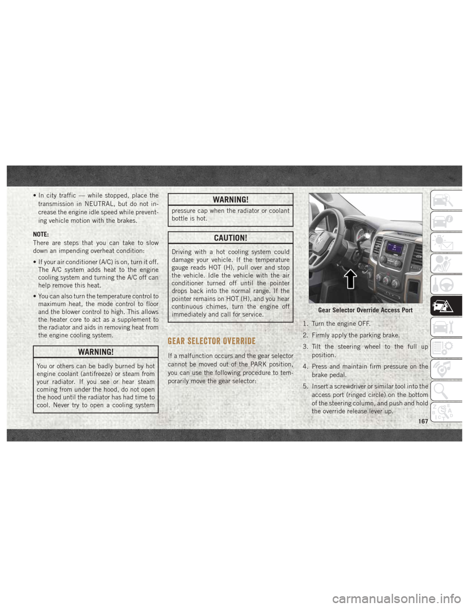
GEAR SELECTOR OVERRIDE
If a malfunction occurs and the gear selector
cannot be moved out of the PARK position,
you can use the following procedure to tem-
porarily move the gear selector: 1. Turn the engine OFF.
2. Firmly apply the parking brake.
3. Tilt the steering wheel to the full up
position.
4. Press and maintain firm pressure on the brake pedal.
5. Insert a screwdriver or similar tool into the access port (ringed circle) on the bottom
of the steering column, and push and hold
the override release lever up.
Gear Selector Override Access Port
167
Page 170 of 298

6. Move the gear selector to the NEUTRALposition.
7. The vehicle may then be started in NEUTRAL.
FREEING A STUCK VEHICLE
If your vehicle becomes stuck in mud, sand,
or snow, it can often be moved using a rock-
ing motion. Turn the steering wheel right and
left to clear the area around the front wheels.
Next, shift back and forth between DRIVE
and REVERSE (with automatic transmission)
or SECOND GEAR and REVERSE (with
manual transmission) while gently pressing
the accelerator. Use the least amount of ac-
celerator pedal pressure that will maintain
the rocking motion, without spinning the
wheels or racing the engine. NOTE:
Push the "ESC Off" switch, to place the Elec-
tronic Stability Control (ESC) system in "Par-
tial Off" mode, before rocking the vehicle.
Refer to “Electronic Brake Control System”
in “Safety” in the Owner’s Manual at
www.mopar.com/en-us/care/owners-manual.html
(U.S. Residents) or www.owners.mopar.ca
(Canadian Residents) for further information.
Once the vehicle has been freed, push the
"ESC Off" switch again to restore "ESC On"
mode.
WARNING!
Fast spinning tires can be dangerous.
Forces generated by excessive wheel
speeds may cause damage, or even failure,
of the axle and tires. A tire could explode
and injure someone. Do not spin your
vehicle's wheels faster than 30 mph
(48 km/h) or for longer than 30 seconds
continuously without stopping when you
are stuck and do not let anyone near a
spinning wheel, no matter what the speed.
CAUTION!
• Racing the engine or spinning the
wheels may lead to transmission over-
heating and failure. Allow the engine to
idle with the transmission in NEUTRAL
for at least one minute after every five
rocking-motion cycles. This will mini-
mize overheating and reduce the risk of
clutch or transmission failure during
prolonged efforts to free a stuck vehicle.
• When “rocking” a stuck vehicle by shift-
ing between DRIVE/SECOND GEAR and
REVERSE, do not spin the wheels faster
than 15 mph (24 km/h), or drivetrain
damage may result.
• Revving the engine or spinning the
wheels too fast may lead to transmission
overheating and failure. It can also dam-
age the tires. Do not spin the wheels
above 30 mph (48 km/h) while in gear
(no transmission shifting occurring).
IN CASE OF EMERGENCY
168
Page 172 of 298

CAUTION!
• Do not use sling type equipment whentowing. Vehicle damage may occur.
• When securing the vehicle to a flat bed
truck, do not attach to front or rear
suspension components. Damage to
your vehicle may result from improper
towing.
Two-Wheel Drive Models
The manufacturer recommends towing your
vehicle with all four wheels OFFthe ground
using a flatbed.
If flatbed equipment is not available, and the
transmission is operable, the vehicle may be
towed (with the rear wheels on the ground)
under the following conditions:
• The transmission must be in NEUTRAL.
• The towing speed must not exceed 30 mph (48 km/h).
• The towing distance must not exceed 15 miles (24 km). If the transmission is not operable, or the
vehicle must be towed faster than 30 mph
(48 km/h) or farther than 15 miles (24 km),
tow with the rear wheels
OFFthe ground.
Acceptable methods are to tow the vehicle on
a flatbed, or with the front wheels raised and
the rear wheels on a towing dolly, or (when
using a suitable steering wheel stabilizer to
hold the front wheels in the straight position)
with rear wheels raised and the front wheels
on the ground.CAUTION!
Towing this vehicle in violation of the
above requirements can cause severe en-
gine and/or transmission damage. Damage
from improper towing is not covered under
the New Vehicle Limited Warranty.
Four-Wheel Drive Models
The manufacturer recommends towing with
all wheels OFFthe ground. Acceptable meth-
ods are to tow the vehicle on a flatbed or with
one end of vehicle raised and the opposite
end on a towing dolly. If flatbed equipment is not available, and the
transfer case is operable, the vehicle may be
towed (in the forward direction, with
ALL
wheels on the ground), IFthe transfer case is
in NEUTRAL and the transmission is in PARK
(for automatic transmissions) or in gear (NOT
in NEUTRAL, for manual transmissions). Re-
fer to “Recreational Towing” in “Starting And
Operating” for further information and de-
tailed instructions.
CAUTION!
• Front or rear wheel lifts must not be used (if the remaining wheels are on the
ground). Internal damage to the trans-
mission or transfer case will occur if a
front or rear wheel lift is used when
towing.
• Towing this vehicle in violation of the
above requirements can cause severe
transmission and/or transfer case dam-
age. Damage from improper towing is
not covered under the New Vehicle Lim-
ited Warranty.IN CASE OF EMERGENCY
170
Page 176 of 298

SCHEDULED SERVICING — GASOLINE
ENGINE
Your vehicle is equipped with an automatic
oil change indicator system. The oil change
indicator system will remind you that it is
time to take your vehicle in for scheduled
maintenance.
Based on engine operation conditions, the oil
change indicator message will illuminate.
This means that service is required for your
vehicle. Operating conditions such as fre-
quent short-trips, trailer tow, extremely hot or
cold ambient temperatures, and E85 fuel
usage will influence when the “Oil Change
Required” message is displayed. Severe Op-
erating Conditions can cause the change oil
message to illuminate as early as
3,500 miles (5,600 km) since last reset.
Have your vehicle serviced as soon as pos-
sible, within the next 500 miles (805 km).
Your authorized dealer will reset the oil
change indicator message after completing
the scheduled oil change. If a scheduled oil
change is performed by someone other than
your authorized dealer, the message can bereset by referring to the steps described under
“Warning And Indicator Lights” or “Instru-
ment Cluster Display” in “Getting To Know
Your Instrument Panel” in your Owner’s
Manual at
www.mopar.com/en-us/care/
owner-manual.html (U.S. Residents) or
www.owners.mopar.ca (Canadian Residents)
for further information.
Gasoline Engines:
Under no circumstances should oil change
intervals exceed 8,000 miles (13,000 km),
twelve months or 350 hours of engine run
time, whichever comes first. The 350 hours
of engine run or idle time is generally only a
concern for fleet customers.
Severe Duty:
Change Engine Oil at 4,000 miles
(6,500 km) or 350 hours of engine run time
if the vehicle is operated in a dusty and off
road environment or is operated predomi-
nately at idle or very low engine RPM’s. This
type of vehicle use is considered Severe Duty. Once A Month Or Before A Long Trip:
• Check engine oil level
• Check windshield washer fluid level
• Check the tire inflation pressures and look
for unusual wear or damage
• Check the fluid levels of the coolant reser- voir, brake master cylinder, power steering
and automatic transmission, and fill as
needed
• Check function of all interior and exterior lights
SERVICING AND MAINTENANCE
174