stop start Ram 4500 Chassis Cab 2018 Owner's Manual
[x] Cancel search | Manufacturer: RAM, Model Year: 2018, Model line: 4500 Chassis Cab, Model: Ram 4500 Chassis Cab 2018Pages: 298, PDF Size: 5.88 MB
Page 146 of 298
• Trailer brakes are recommended for trailersover 1,000 lbs (453 kg) and required for
trailers in excess of 2,000 lbs (907 kg).
WARNING!
•Do not connect trailer brakes to your vehi-
cle's hydraulic brake lines. It can overload
your brake system and cause it to fail. You
might not have brakes when you need them
and could have a collision.
• Towing any trailer will increase your stopping distance. When towing you
should allow for additional space be-
tween your vehicle and the vehicle in
front of you. Failure to do so could result
in a collision.
CAUTION!
If the trailer weighs more than 1,000 lbs
(453 kg) loaded, it should have its own
brakes and they should be of adequate
capacity. Failure to do this could lead to
accelerated brake lining wear, higher
brake pedal effort, and longer stopping
distances.
Integrated Trailer Brake Module — If Equipped
Your vehicle may have an Integrated Trailer
Brake Module (ITBM) for Electric and Elec-
tric Over Hydraulic (EOH) trailer brakes.
NOTE:
This module has been designed and verified
with electric trailer brakes and new electric
over hydraulic systems. Some previous EOH
systems may not be compatible with ITBM. The user interface consists of the following:
Manual Brake Control Lever
Slide the manual brake control lever to the
left to activate power to the trailer's electric
brakes independent of the tow vehicle's
brakes. If the manual brake control lever is
activated while the brake is also applied, the
greater of the two inputs determines the
power sent to the trailer brakes.
The trailer and the vehicle's brake lamps will
come on when either vehicle braking or
manual trailer brakes are applied.
Trailer Brake Status Indicator Light
This light indicates the trailer electrical con-
nection status.
If no electrical connection is detected after
the ignition is turned on, pushing the GAIN
adjustment button or sliding the manual
brake control lever will display the GAIN
setting for 10 seconds and the “Trailer Brake
Status Indicator Light” will not be displayed.
If a fault is detected in the trailer wiring or the
Integrated Trailer Brake Module (ITBM), the
“Trailer Brake Status Indicator Light” will flash.
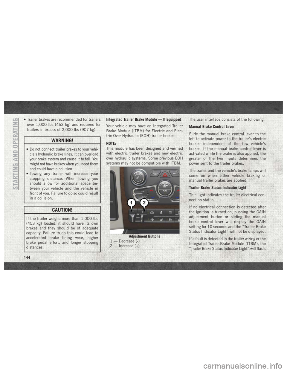
Adjustment Buttons1 — Decrease (-)
2 — Increase (+)
STARTING AND OPERATING
144
Page 148 of 298
Light ElectricHeavy ElectricLight EOHHeavy EOH
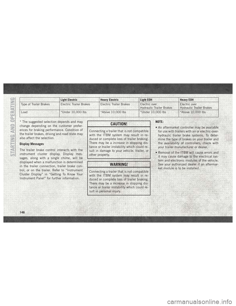
Type of Trailer Brakes Electric Trailer Brakes Electric Trailer Brakes Electric over Hydraulic Trailer BrakesElectric over
Hydraulic Trailer Brakes
Load *Under 10,000 lbs *Above 10,000 lbs *Under 10,000 lbs *Above 10,000 lbs
* The suggested selection depends and may
change depending on the customer prefer-
ences for braking performance. Condition of
the trailer brakes, driving and road state may
also affect the selection.
Display Messages
The trailer brake control interacts with the
instrument cluster display. Display mes-
sages, along with a single chime, will be
displayed when a malfunction is determined
in the trailer connection, trailer brake con-
trol, or on the trailer. Refer to “Instrument
Cluster Display” in “Getting To Know Your
Instrument Panel” for further information.CAUTION!
Connecting a trailer that is not compatible
with the ITBM system may result in re-
duced or complete loss of trailer braking.
There may be a increase in stopping dis-
tance or trailer instability which could re-
sult in damage to your vehicle, trailer, or
other property.
WARNING!
Connecting a trailer that is not compatible
with the ITBM system may result in re-
duced or complete loss of trailer braking.
There may be a increase in stopping dis-
tance or trailer instability which could re-
sult in personal injury. NOTE:
• An aftermarket controller may be available
for use with trailers with air or electric-over-
hydraulic trailer brake systems. To deter-
mine the type of brakes on your trailer and
the availability of controllers, check with
your trailer manufacturer or dealer.
• Removal of the ITBM will cause errors and it may cause damage to the electrical sys-
tem and electronic modules of the vehicle.
See your authorized dealer if an aftermar-
ket module is to be installed.
STARTING AND OPERATING
146
Page 151 of 298

WARNING!
matic transmission is in PARK (or manual
transmission is in gear). The parking brake
should always be applied when the driver
is not in the vehicle.
CAUTION!
It is necessary to follow these steps to be
certain that the transfer case is fully in
NEUTRAL (N) before recreational towing
to prevent damage to internal parts.
1. Bring the vehicle to a complete stop on level ground, with the engine running.
Firmly apply the parking brake.
2. Shift the transmission to NEUTRAL.
3. Press and hold the brake pedal.
4. Depress the clutch pedal on a manual transmission.
5. Shift the transfer case into NEUTRAL: • With manual shift transfer case, shift
the transfer case lever into NEUTRAL
(N).
• With electronic shift transfer case, push and hold the transfer case NEU-
TRAL (N) button. Some models have a
small, recessed "N" button (at the cen-
ter of the transfer case switches) that
must be pressed using a ballpoint pen
or similar object. Other models have a
rectangular NEUTRAL switch, below
the rotary transfer case control knob.
The NEUTRAL (N) indicator light will
blink while the shift is in progress. The
light will stop blinking (stay on solid)
when the shift to NEUTRAL (N) is com-
plete. After the shift is completed and
the NEUTRAL (N) light stays on, re-
lease the NEUTRAL (N) button.
6. Release the parking brake.
7. Shift the transmission into REVERSE. 8. Release the brake pedal (and clutch pedal
on manual transmissions) for five seconds
and ensure that there is no vehicle
movement.
9. Repeat steps seven and eight with auto- matic transmission in DRIVE or manual
transmission in first gear.
10. Shift the transmission to NEUTRAL. Firmly apply the parking brake. Turn OFF
the engine. For vehicles with Keyless
Enter-N-Go, push and hold the ENGINE
START/STOP button until the engine
shuts off.
11. Shift the transmission into PARK or place manual transmission in gear (NOT
in NEUTRAL).
12. Place the ignition in the OFF mode, and remove the key fob.
13. Attach the vehicle to the tow vehicle using a suitable tow bar.
14. Release the parking brake.
149
Page 152 of 298

NOTE:
With electronic shift transfer case:
• Steps 2 through 4 are requirements thatmust be met before pushing the NEUTRAL
(N) button, and must continue to be met
until the shift has been completed. If any of
these requirements are not met before
pushing the NEUTRAL (N) button or are no
longer met during the shift, the NEUTRAL
(N) indicator light will flash continuously
until all requirements are met or until the
NEUTRAL (N) button is released.
• The ignition must be in the ON/RUN mode for a shift to take place and for the position
indicator lights to be operable. If the igni-
tion is not in the ON/RUN mode, the shift
will not take place and no position indicator
lights will be on or flashing.
• A flashing NEUTRAL (N) position indicator light indicates that shift requirements have
not been met.Shifting Out Of NEUTRAL (N)
Use the following procedure to prepare your
vehicle for normal usage:
1. Bring the vehicle to a complete stop,
leaving it connected to the tow vehicle.
2. Firmly apply the parking brake.
3. Turn the ignition to the ON/RUN mode, but do not start the engine.
4. Press and hold the brake pedal.
5. Shift the transmission into NEUTRAL.
• With manual shift transfer case, shiftthe transfer case lever to the desired
position.
• With electronic shift transfer case with rotary selector switch, push and hold
the transfer case NEUTRAL (N) button
until the NEUTRAL (N) indicator light
turns off. After the NEUTRAL (N) indi-
cator light turns off, release the NEU-
TRAL (N) button. After the NEUTRAL
(N) button has been released, the
transfer case will shift to the position
indicated by the selector switch. • With electronic shift transfer case with
push-button selector switch, push and
hold the switch for the desired transfer
case position, until the NEUTRAL (N)
indicator light turns off and the desired
position indicator light turns on.
NOTE:
When shifting out of transfer case NEUTRAL
(N), the engine should remain OFF to avoid
gear clash.
6. Shift automatic transmission into PARK.
7. Release the brake pedal (and clutch pedal on a manual transmission).
8. Disconnect vehicle from the tow vehicle.
9. Start the engine.
10. Press and hold the brake pedal.
11. Release the parking brake.
12. Shift the transmission into gear, release the brake pedal (and clutch pedal on
manual transmissions), and check that
the vehicle operates normally.
STARTING AND OPERATING
150
Page 158 of 298

CavityCartridge Fuse Micro Fuse Description
F09 40 Amp Green (Special
Services Vehicle & Cum- mins Diesel) –
Diesel Fuel Heater – If Equipped
F10 40 Amp Green –Body Controller / Exterior Lighting #2
F10 50 Amp Red –Body Controller / Exterior Lighting #2 – If Equipped with
Stop/Start
F11 30 Amp Pink –Integrated Trailer Brake Module – If Equipped
F12 40 Amp Green –Body Controller #3 / Power Locks
F13 40 Amp Green – Blower Motor
F14 40 Amp Green –Body Controller #4 / Interior Lighting
F16 30 Amp Pink –Smart Bar – If Equipped
F19 20 Amp Blue (1500 LD
Diesel)
30 Amp Pink (Cummins Diesel) –
SCR – If Equipped
F20 30 Amp Pink –Passenger Door Module
F21 30 Amp Pink –Drive Train Control Module
F22 20 Amp Blue
30 Amp Pink (Cummins Diesel) –
Engine Control Module
F23 30 Amp Pink –Body Controller #1 / Interior Lighting
F24 30 Amp Pink –Driver Door Module
F25 30 Amp Pink – Front Wiper
F26 30 Amp Pink –Antilock Brakes / Stability Control Module / Valves
F28 20 Amp Blue –Trailer Tow Backup Lights – If Equipped
IN CASE OF EMERGENCY
156
Page 170 of 298

6. Move the gear selector to the NEUTRALposition.
7. The vehicle may then be started in NEUTRAL.
FREEING A STUCK VEHICLE
If your vehicle becomes stuck in mud, sand,
or snow, it can often be moved using a rock-
ing motion. Turn the steering wheel right and
left to clear the area around the front wheels.
Next, shift back and forth between DRIVE
and REVERSE (with automatic transmission)
or SECOND GEAR and REVERSE (with
manual transmission) while gently pressing
the accelerator. Use the least amount of ac-
celerator pedal pressure that will maintain
the rocking motion, without spinning the
wheels or racing the engine. NOTE:
Push the "ESC Off" switch, to place the Elec-
tronic Stability Control (ESC) system in "Par-
tial Off" mode, before rocking the vehicle.
Refer to “Electronic Brake Control System”
in “Safety” in the Owner’s Manual at
www.mopar.com/en-us/care/owners-manual.html
(U.S. Residents) or www.owners.mopar.ca
(Canadian Residents) for further information.
Once the vehicle has been freed, push the
"ESC Off" switch again to restore "ESC On"
mode.
WARNING!
Fast spinning tires can be dangerous.
Forces generated by excessive wheel
speeds may cause damage, or even failure,
of the axle and tires. A tire could explode
and injure someone. Do not spin your
vehicle's wheels faster than 30 mph
(48 km/h) or for longer than 30 seconds
continuously without stopping when you
are stuck and do not let anyone near a
spinning wheel, no matter what the speed.
CAUTION!
• Racing the engine or spinning the
wheels may lead to transmission over-
heating and failure. Allow the engine to
idle with the transmission in NEUTRAL
for at least one minute after every five
rocking-motion cycles. This will mini-
mize overheating and reduce the risk of
clutch or transmission failure during
prolonged efforts to free a stuck vehicle.
• When “rocking” a stuck vehicle by shift-
ing between DRIVE/SECOND GEAR and
REVERSE, do not spin the wheels faster
than 15 mph (24 km/h), or drivetrain
damage may result.
• Revving the engine or spinning the
wheels too fast may lead to transmission
overheating and failure. It can also dam-
age the tires. Do not spin the wheels
above 30 mph (48 km/h) while in gear
(no transmission shifting occurring).
IN CASE OF EMERGENCY
168
Page 189 of 298
If the vehicle experiences a sudden loss of
engine power while being driven in heavy
snow or rain, or when plowing snow, and/or
the “SERVICE AIR FILTER” message is dis-
played on the instrument cluster along with a
chime that repeats every 60 seconds, visually
inspect the air filter for snow/ice build up or
extreme water saturation. If the air filter is
not damaged, remove all snow/ice and rein-
stall air filter. If the air filter is damaged,
replace filter element.
NOTE:
The air filter housing contains a Mass Air
Flow sensor. This sensor is critical to proper
engine operation and component longevity.
Any damage or modification to this sensor
could result in major engine and/or exhaust
aftertreatment damage. We recommend you
use Mopar brand parts.
Even though your vehicle is equipped with an
Air Filter Monitor, a visual inspection of the
air cleaner filter element is recommended
every 15,000 miles (24,000km) or
12 months – whichever occurs first.Under nocircumstances should the air cleaner filter ele-
ment exceed 30,000 miles (48,000 km) or
24 months, whichever comes first.
CAUTION!
Many aftermarket performance air filter
elements do not adequately filter the air
entering the engine. Use of such filters can
severely damage your engine.
Draining Fuel/Water Separator
Filter
There are two fuel filter assemblies. One is
located on the driver's side of the engine. The
best access to this water drain valve is from
under the hood. The second one is on the
under body, located in front of the rear axle
above the drive shaft on pick-up models. The
Chassis Cab models second filter location is
on the frame behind the front axle. The best
access to this water drain valve is from under
the vehicle.
CAUTION!
• Do not drain the fuel/water separator
filter when the engine is running.
• Diesel fuel will damage blacktop paving
surfaces. Drain the filter into an appro-
priate container.
If water is detected in the water separator
while the engine is running, or while the
ignition switch is in the ON position, the
“Water In Fuel Indicator Light” will illumi-
nate and an audible chime will be heard five
times. At this point you should stop the
engine and drain the water from both of the
filters.
CAUTION!
If the “Water In Fuel Indicator Light” re-
mains on, DO NOT START the engine be-
fore you drain water from the fuel filters to
avoid engine damage.
If the “Water In Fuel Indicator Light” comes
on and a single chime is heard while you are
driving, or with the ignition switch in the ON
187
Page 235 of 298
Seek Previous/Next Buttons
Seek Up
Press and release the “Seek Up”button
on the touchscreen to tune the radio to the
next listenable station or channel.
During a Seek Up function, if the radio
reaches the starting station after passing
through the entire band two times, the radio
will stop at the station where it began.
Fast Seek Up
Press and hold the “Seek Up”button on
the touchscreen to advance the radio through
the available stations or channels at a faster
rate, the radio stops at the next available
station or channel when the button on the
touchscreen is released.
Seek Down
Press and release the “Seek Down”but-
ton on the touchscreen to tune the radio to
the next listenable station or channel.
During a Seek Down function, if the radio
reaches the starting station after passing
through the entire band two times, the radio
will stop at the station where it began. Fast Seek Down
Press and hold the “Seek Down”button
on the touchscreen to advance the radio
through the available stations or channel at a
faster rate, the radio stops at the next avail-
able station or channel when the button on
the touchscreen is released.
Store Radio Presets
The Radio stores up to 12 presets in each of
the Radio modes. There are four visible pre-
sets at the top of the radio screen. Pressing
the “All” button on the touchscreen on the
radio home screen will display all of the
preset stations for that mode.
To store a radio preset manually, follow the
steps below:
1. Tune to the desired station.
2. Press and hold the desired numbered but- ton on the touchscreen for more than two
seconds or until you hear a confirmation
beep.
Media Mode
Audio Source Selection
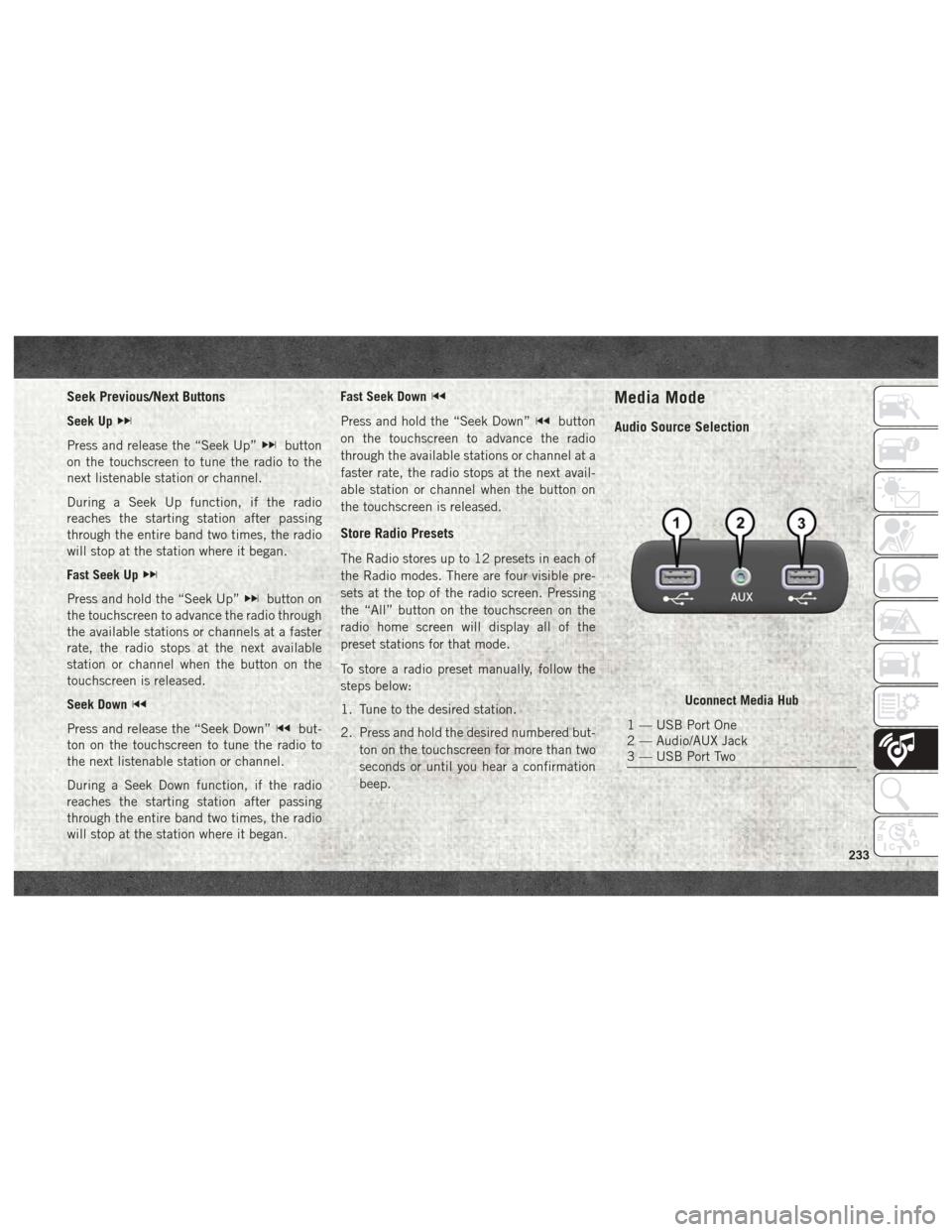
Uconnect Media Hub
1 — USB Port One
2 — Audio/AUX Jack
3 — USB Port Two
233
Page 275 of 298
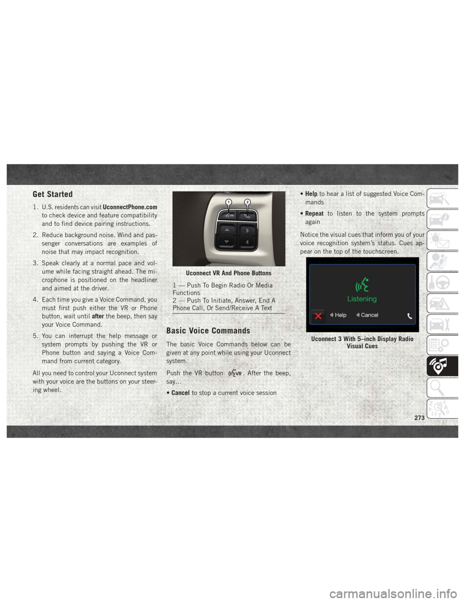
Get Started
1.U.S. residents can visitUconnectPhone.com
to check device and feature compatibility
and to find device pairing instructions.
2. Reduce background noise. Wind and pas- senger conversations are examples of
noise that may impact recognition.
3. Speak clearly at a normal pace and vol- ume while facing straight ahead. The mi-
crophone is positioned on the headliner
and aimed at the driver.
4. Each time you give a Voice Command, you must first push either the VR or Phone
button, wait until afterthe beep, then say
your Voice Command.
5. You can interrupt the help message or system prompts by pushing the VR or
Phone button and saying a Voice Com-
mand from current category.
All you need to control your Uconnect system
with your voice are the buttons on your steer-
ing wheel.
Basic Voice Commands
The basic Voice Commands below can be
given at any point while using your Uconnect
system.
Push the VR button
. After the beep,
say…
• Cancel to stop a current voice session •
Help to hear a list of suggested Voice Com-
mands
• Repeat to listen to the system prompts
again
Notice the visual cues that inform you of your
voice recognition system’s status. Cues ap-
pear on the top of the touchscreen.
Uconnect VR And Phone Buttons
1 — Push To Begin Radio Or Media
Functions
2 — Push To Initiate, Answer, End A
Phone Call, Or Send/Receive A Text
Uconnect 3 With 5–inch Display Radio Visual Cues
273