brakes Ram 4500 Chassis Cab 2018 User Guide
[x] Cancel search | Manufacturer: RAM, Model Year: 2018, Model line: 4500 Chassis Cab, Model: Ram 4500 Chassis Cab 2018Pages: 298, PDF Size: 5.88 MB
Page 131 of 298
WARNING!
• Never leave children alone in a vehicle,or with access to an unlocked vehicle.
Allowing children to be in a vehicle un-
attended is dangerous for a number of
reasons. A child or others could be seri-
ously or fatally injured. Children should
be warned not to touch the parking
brake, brake pedal or the transmission
gear selector.
•
Do not leave the key fob in or near the
vehicle (or in a location accessible to chil-
dren), and do not leave the ignition (in a
vehicle equipped with Keyless Enter-N-
Go) in the ACC or ON/RUN mode. A child
could operate power windows, other con-
trols, or move the vehicle.
CAUTION!
Damage to the transmission may occur if the
following precautions are not observed:
• Shift into or out of PARK or REVERSE
only after the vehicle has come to a
complete stop.
CAUTION!
• Do not shift between PARK, REVERSE,NEUTRAL, or DRIVE when the engine is
above idle speed.
• Before shifting into any gear, make sure
your foot is firmly pressing the brake
pedal.
NOTE:
You must press and hold the brake pedal
while shifting out of PARK.
Key Ignition Park Interlock
This vehicle is equipped with a Key Ignition
Park Interlock which requires the transmis-
sion to be in PARK before the ignition can be
turned to the LOCK/OFF (key removal) posi-
tion. The key fob can only be removed from
the ignition when the ignition is in the LOCK/
OFF position, and the transmission is locked
in PARK whenever the ignition is in the
LOCK/OFF position. NOTE:
If a malfunction occurs, the system will trap
the key fob in the ignition to warn you that
this safety feature is inoperable. The engine
can be started and stopped but the key fob
cannot be removed until you obtain service.
Brake/Transmission Shift
Interlock System
This vehicle is equipped with a Brake Trans-
mission Shift Interlock system (BTSI) that
holds the transmission gear selector in PARK
unless the brakes are applied. To shift the
transmission out of PARK, the ignition must
be in the ON/RUN mode (engine running or
not) and the brake pedal must be pressed.
Six–Speed Automatic
Transmission — If Equipped
Chassis Cab models (with automatic trans-
mission) may use either the AS66RC or
AS69RC transmission (which are equipped
with a Power Take-Off (PTO) access cover on
the side of the transmission case), or the
66RFE transmission (which has no PTO ac-
cess cover).
129
Page 133 of 298

If the transmission cannot be reset, autho-
rized dealer service is required.
Electronic Range Select (ERS) Operation
The Electronic Range Select (ERS) shift con-
trol allows the driver to limit the highest
available gear when the transmission is in
DRIVE. For example, if you set the transmis-
sion gear limit to 4 (fourth gear), the trans-
mission will not shift above fourth gear, but
will shift through the lower gears normally.
You can switch between DRIVE and ERS
mode at any vehicle speed. When the gear
selector is in the DRIVE position, the trans-
mission will operate automatically, shifting
between all available gears. Tapping the ERS
(-) switch will activate ERS mode, display the
current gear in the instrument cluster, and
set that gear as the top available gear. Once
in ERS mode, tapping (-) or (+) will change
the top available gear.To exit ERS mode, simply push and hold the
ERS (+) switch until the gear limit display
disappears from the instrument cluster.
WARNING!
Do not downshift for additional engine
braking on a slippery surface. The drive
wheels could lose their grip and the ve-
hicle could skid, causing a collision or
personal injury.
NOTE:
To select the proper gear position for maxi-
mum deceleration (engine braking), simply
push and hold the ERS (-) switch. The trans-
mission will shift to the range from which the
vehicle can best be slowed down.
CAUTION!
When using ERS for engine braking while
descending steep grades, be careful not to
overspeed the engine. Apply the brakes as
needed to prevent engine overspeed.
FOUR-WHEEL DRIVE OPERATION —
IF EQUIPPED
• Four-wheel drive trucks are equipped with either a manually shifted transfer case or an
electronically shifted transfer case. Refer to
the operating instructions for electronic
transfer case, located in this section for
further information.
• For further information on the manually shifted transfer case, refer to “Four Wheel
Drive Operation” in “Starting And Operat-
ing” in your Owner’s Manual located at
www.mopar.com/en-us/care/owners-manual.html
(U.S. Residents) or www.owners.mopar.ca
(Canadian Residents).
Column Gear Selector
131
Page 145 of 298

CAUTION!
• Then, during the first 500 miles(805 km) that a trailer is towed, do not
drive over 50 mph (80 km/h) and do not
make starts at full throttle. This helps
the engine and other parts of the vehicle
wear in at the heavier loads.
Perform the maintenance listed in the
“Scheduled Servicing”. Refer to “Scheduled
Servicing” in “Servicing And Maintenance”
for the proper maintenance intervals. When
towing a trailer, never exceed the GAWR or
GCWR ratings.
WARNING!
Improper towing can lead to a collision.
Follow these guidelines to make your
trailer towing as safe as possible:
• Make certain that the load is secured in the trailer and will not shift during travel.
When trailering cargo that is not fully
secured, dynamic load shifts can occur
that may be difficult for the driver to
WARNING!
control. You could lose control of your
vehicle and have a collision.
• When hauling cargo or towing a trailer,
do not overload your vehicle or trailer.
Overloading can cause a loss of control,
poor performance or damage to brakes,
axle, engine, transmission, steering,
suspension, chassis structure or tires.
• Safety chains must always be used be-
tween your vehicle and trailer. Always
connect the chains to the hook retainers
of the vehicle hitch. Cross the chains
under the trailer tongue and allow
enough slack for turning corners.
• Vehicles with trailers should not be
parked on a grade. When parking, apply
the parking brake on the tow vehicle. Put
the tow vehicle transmission in PARK.
For four-wheel drive vehicles, make sure
the transfer case is not in NEUTRAL.
Always, block or "chock" the trailer
wheels.
• GCWR must not be exceeded.
WARNING!
• Total weight must be distributed between
the tow vehicle and the trailer such that the
following four ratings are not exceeded:
1. GVWR
2. GTW
3. GAWR
4. Tongue weight rating for the trailer hitch utilized.
Towing Requirements — Trailer Brakes
•Do notinterconnect the hydraulic brake
system or vacuum system of your vehicle
with that of the trailer. This could cause
inadequate braking and possible personal
injury.
• An electronically actuated trailer brake controller is required when towing a trailer
with electronically actuated brakes. When
towing a trailer equipped with a hydraulic
surge actuated brake system, an electronic
brake controller is not required.
143
Page 146 of 298
• Trailer brakes are recommended for trailersover 1,000 lbs (453 kg) and required for
trailers in excess of 2,000 lbs (907 kg).
WARNING!
•Do not connect trailer brakes to your vehi-
cle's hydraulic brake lines. It can overload
your brake system and cause it to fail. You
might not have brakes when you need them
and could have a collision.
• Towing any trailer will increase your stopping distance. When towing you
should allow for additional space be-
tween your vehicle and the vehicle in
front of you. Failure to do so could result
in a collision.
CAUTION!
If the trailer weighs more than 1,000 lbs
(453 kg) loaded, it should have its own
brakes and they should be of adequate
capacity. Failure to do this could lead to
accelerated brake lining wear, higher
brake pedal effort, and longer stopping
distances.
Integrated Trailer Brake Module — If Equipped
Your vehicle may have an Integrated Trailer
Brake Module (ITBM) for Electric and Elec-
tric Over Hydraulic (EOH) trailer brakes.
NOTE:
This module has been designed and verified
with electric trailer brakes and new electric
over hydraulic systems. Some previous EOH
systems may not be compatible with ITBM. The user interface consists of the following:
Manual Brake Control Lever
Slide the manual brake control lever to the
left to activate power to the trailer's electric
brakes independent of the tow vehicle's
brakes. If the manual brake control lever is
activated while the brake is also applied, the
greater of the two inputs determines the
power sent to the trailer brakes.
The trailer and the vehicle's brake lamps will
come on when either vehicle braking or
manual trailer brakes are applied.
Trailer Brake Status Indicator Light
This light indicates the trailer electrical con-
nection status.
If no electrical connection is detected after
the ignition is turned on, pushing the GAIN
adjustment button or sliding the manual
brake control lever will display the GAIN
setting for 10 seconds and the “Trailer Brake
Status Indicator Light” will not be displayed.
If a fault is detected in the trailer wiring or the
Integrated Trailer Brake Module (ITBM), the
“Trailer Brake Status Indicator Light” will flash.
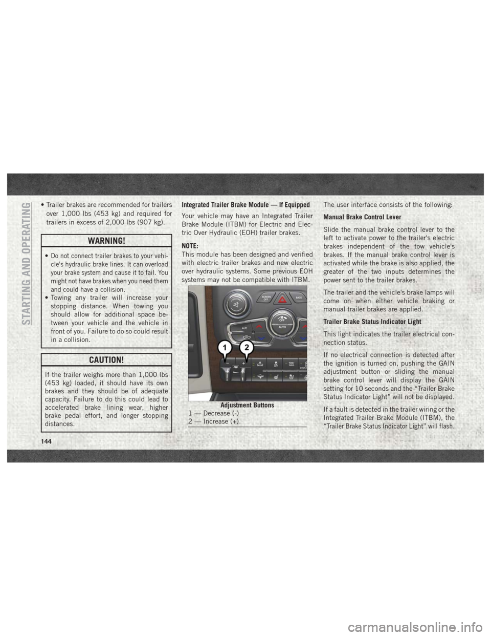
Adjustment Buttons1 — Decrease (-)
2 — Increase (+)
STARTING AND OPERATING
144
Page 147 of 298
GAIN Adjustment Buttons (+/-)
Pushing these buttons will adjust the brake
control power output to the trailer brakes in
0.5 increments. The GAIN setting can be
increased to a maximum of 10 or decreased
to a minimum of 0 (no trailer braking).
GAIN
The GAIN setting is used to set the trailer
brake control for the specific towing condi-
tion and should be changed as towing condi-
tions change. Changes to towing conditions
include trailer load, vehicle load, road condi-
tions and weather.
Adjusting GAIN
NOTE:
This should only be performed in a traffic free
environment at speeds of approximately 20–
25 mph (30–40 km/h).
1. Make sure the trailer brakes are in goodworking condition, functioning normally
and properly adjusted. See your trailer
dealer if necessary. 2. Hook up the trailer and make the electri-
cal connections according to the trailer
manufacturer's instructions.
3. When a trailer with electric/EOH brakes is plugged in, the trailer connected message
should appear in the instrument cluster
display (if the connection is not recog-
nized by the ITBM, braking functions will
not be available), the GAIN setting will
illuminate and the correct type of trailer
must be selected from the instrument
cluster display options.
4. Push the UP or DOWN button on the steering wheel until “TRAILER TOW” ap-
pears on the screen.
5. Push the RIGHT arrow on the steering wheel to enter “TRAILER TOW”.
6. Push the UP or DOWN buttons until the Trailer Brake Type appears on the screen. 7. Push the RIGHT arrow and then push the
UP or DOWN buttons until the proper
Trailer Brake Type appears on the screen.
8. In a traffic-free environment, tow the trailer on a dry, level surface at a speed of
20–25 mph (30–40 km/h) and squeeze
the manual brake control lever
completely.
9. If the trailer wheels lockup (indicated by squealing tires), reduce the GAIN setting;
if the trailer wheels turn freely, increase
the GAIN setting.
Repeat steps 8 and 9 until the GAIN setting
is at a point just below trailer wheel lockup. If
towing a heavier trailer, trailer wheel lockup
may not be attainable even with the maxi-
mum GAIN setting of 10.
145
Page 148 of 298
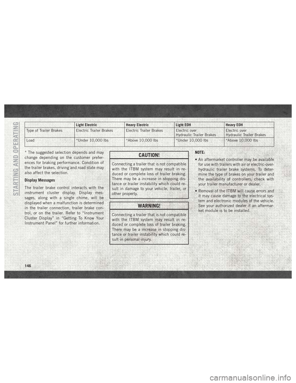
Light ElectricHeavy ElectricLight EOHHeavy EOH
Type of Trailer Brakes Electric Trailer Brakes Electric Trailer Brakes Electric over Hydraulic Trailer BrakesElectric over
Hydraulic Trailer Brakes
Load *Under 10,000 lbs *Above 10,000 lbs *Under 10,000 lbs *Above 10,000 lbs
* The suggested selection depends and may
change depending on the customer prefer-
ences for braking performance. Condition of
the trailer brakes, driving and road state may
also affect the selection.
Display Messages
The trailer brake control interacts with the
instrument cluster display. Display mes-
sages, along with a single chime, will be
displayed when a malfunction is determined
in the trailer connection, trailer brake con-
trol, or on the trailer. Refer to “Instrument
Cluster Display” in “Getting To Know Your
Instrument Panel” for further information.CAUTION!
Connecting a trailer that is not compatible
with the ITBM system may result in re-
duced or complete loss of trailer braking.
There may be a increase in stopping dis-
tance or trailer instability which could re-
sult in damage to your vehicle, trailer, or
other property.
WARNING!
Connecting a trailer that is not compatible
with the ITBM system may result in re-
duced or complete loss of trailer braking.
There may be a increase in stopping dis-
tance or trailer instability which could re-
sult in personal injury. NOTE:
• An aftermarket controller may be available
for use with trailers with air or electric-over-
hydraulic trailer brake systems. To deter-
mine the type of brakes on your trailer and
the availability of controllers, check with
your trailer manufacturer or dealer.
• Removal of the ITBM will cause errors and it may cause damage to the electrical sys-
tem and electronic modules of the vehicle.
See your authorized dealer if an aftermar-
ket module is to be installed.
STARTING AND OPERATING
146
Page 157 of 298

FUSES
WARNING!
• When replacing a blown fuse, always usean appropriate replacement fuse with
the same amp rating as the original fuse.
Never replace a fuse with another fuse of
higher amp rating. Never replace a
blown fuse with metal wires or any other
material. Do not place a fuse inside a
circuit breaker cavity or vice versa. Fail-
ure to use proper fuses may result in
serious personal injury, fire and/or prop-
erty damage.
WARNING!
• Before replacing a fuse, make sure thatthe ignition is off and that all the other
services are switched off and/or disen-
gaged.
• If the replaced fuse blows again, contact
an authorized dealer.
• If a general protection fuse for safety
systems (air bag system, braking sys-
tem), power unit systems (engine sys-
tem, transmission system) or steering
system blows, contact an authorized
dealer.
Power Distribution Center
The Power Distribution Center is located in
the engine compartment near the battery.
This center contains cartridge fuses, micro
fuses, relays, and circuit breakers. A descrip-
tion of each fuse and component may be
stamped on the inside cover, otherwise the
cavity number of each fuse is stamped on the
inside cover that corresponds to the following
chart.
Cavity Cartridge Fuse Micro Fuse Description
F01 80 Amp Black –Rad Fan Control Module – If Equipped
F03 60 Amp Yellow –Rad Fan – If Equipped
F05 40 Amp Green –Compressor for Air Suspension – If Equipped
F06 40 Amp Green –Antilock Brakes/Electronic Stability Control Pump
F07 40 Amp Green – Starter Solenoid
F08 20 Amp Blue (1500 LD/
Cummins Diesel) –
Emissions Diesel – If Equipped
155
Page 158 of 298

CavityCartridge Fuse Micro Fuse Description
F09 40 Amp Green (Special
Services Vehicle & Cum- mins Diesel) –
Diesel Fuel Heater – If Equipped
F10 40 Amp Green –Body Controller / Exterior Lighting #2
F10 50 Amp Red –Body Controller / Exterior Lighting #2 – If Equipped with
Stop/Start
F11 30 Amp Pink –Integrated Trailer Brake Module – If Equipped
F12 40 Amp Green –Body Controller #3 / Power Locks
F13 40 Amp Green – Blower Motor
F14 40 Amp Green –Body Controller #4 / Interior Lighting
F16 30 Amp Pink –Smart Bar – If Equipped
F19 20 Amp Blue (1500 LD
Diesel)
30 Amp Pink (Cummins Diesel) –
SCR – If Equipped
F20 30 Amp Pink –Passenger Door Module
F21 30 Amp Pink –Drive Train Control Module
F22 20 Amp Blue
30 Amp Pink (Cummins Diesel) –
Engine Control Module
F23 30 Amp Pink –Body Controller #1 / Interior Lighting
F24 30 Amp Pink –Driver Door Module
F25 30 Amp Pink – Front Wiper
F26 30 Amp Pink –Antilock Brakes / Stability Control Module / Valves
F28 20 Amp Blue –Trailer Tow Backup Lights – If Equipped
IN CASE OF EMERGENCY
156
Page 160 of 298
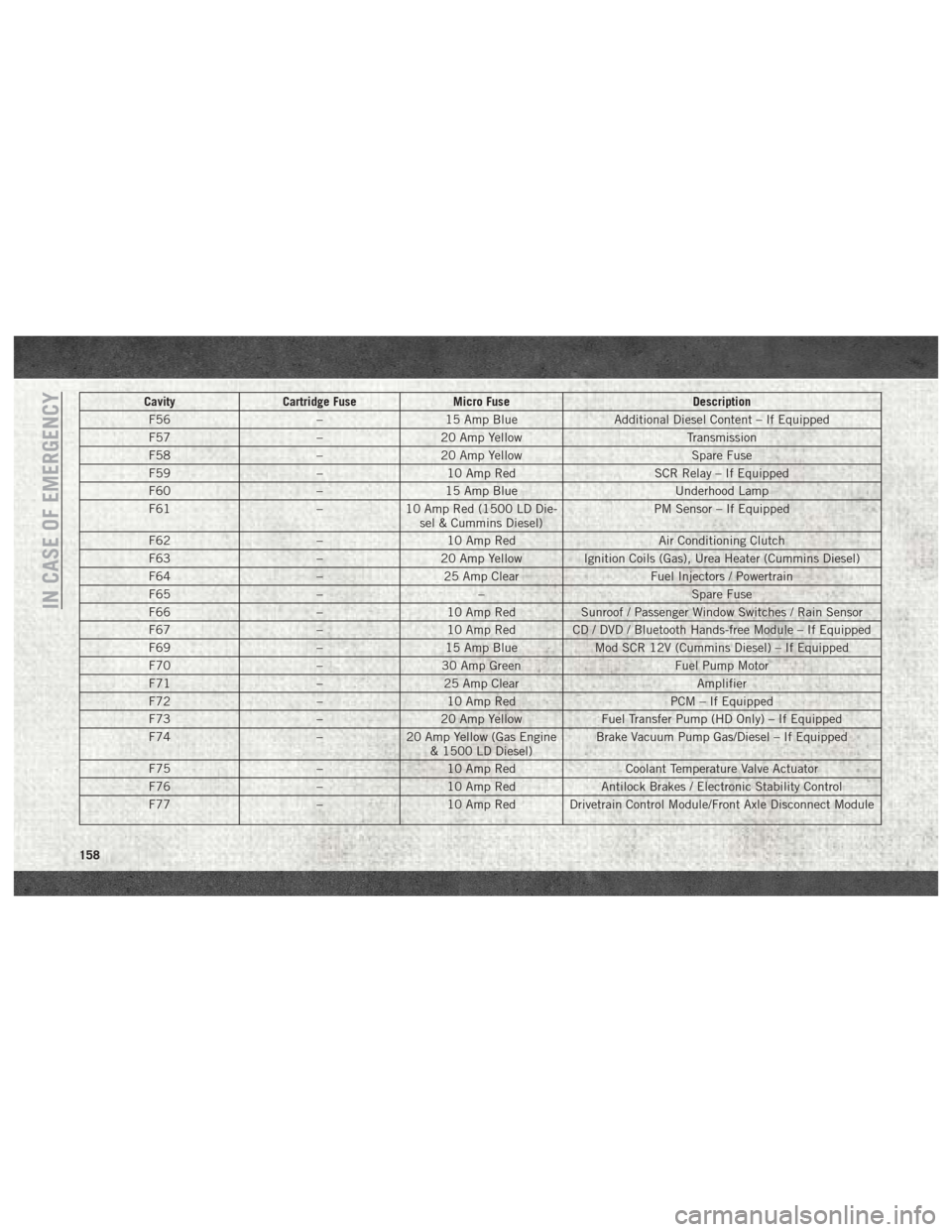
CavityCartridge Fuse Micro Fuse Description
F56 –15 Amp Blue Additional Diesel Content – If Equipped
F57 –20 Amp Yellow Transmission
F58 –20 Amp Yellow Spare Fuse
F59 –10 Amp Red SCR Relay – If Equipped
F60 –15 Amp Blue Underhood Lamp
F61 –10 Amp Red (1500 LD Die-
sel & Cummins Diesel) PM Sensor – If Equipped
F62 –10 Amp Red Air Conditioning Clutch
F63 –20 Amp Yellow Ignition Coils (Gas), Urea Heater (Cummins Diesel)
F64 –25 Amp Clear Fuel Injectors / Powertrain
F65 –– Spare Fuse
F66 –10 Amp Red Sunroof / Passenger Window Switches / Rain Sensor
F67 –10 Amp Red CD / DVD / Bluetooth Hands-free Module – If Equipped
F69 –15 Amp Blue Mod SCR 12V (Cummins Diesel) – If Equipped
F70 –30 Amp Green Fuel Pump Motor
F71 –25 Amp Clear Amplifier
F72 –10 Amp Red PCM – If Equipped
F73 –20 Amp Yellow Fuel Transfer Pump (HD Only) – If Equipped
F74 –20 Amp Yellow (Gas Engine
& 1500 LD Diesel) Brake Vacuum Pump Gas/Diesel – If Equipped
F75 –10 Amp Red Coolant Temperature Valve Actuator
F76 –10 Amp Red Antilock Brakes / Electronic Stability Control
F77 –10 Amp Red Drivetrain Control Module/Front Axle Disconnect Module
IN CASE OF EMERGENCY
158
Page 169 of 298
• In city traffic — while stopped, place thetransmission in NEUTRAL, but do not in-
crease the engine idle speed while prevent-
ing vehicle motion with the brakes.
NOTE:
There are steps that you can take to slow
down an impending overheat condition:
• If your air conditioner (A/C) is on, turn it off. The A/C system adds heat to the engine
cooling system and turning the A/C off can
help remove this heat.
• You can also turn the temperature control to maximum heat, the mode control to floor
and the blower control to high. This allows
the heater core to act as a supplement to
the radiator and aids in removing heat from
the engine cooling system.
WARNING!
You or others can be badly burned by hot
engine coolant (antifreeze) or steam from
your radiator. If you see or hear steam
coming from under the hood, do not open
the hood until the radiator has had time to
cool. Never try to open a cooling system
WARNING!
pressure cap when the radiator or coolant
bottle is hot.
CAUTION!
Driving with a hot cooling system could
damage your vehicle. If the temperature
gauge reads HOT (H), pull over and stop
the vehicle. Idle the vehicle with the air
conditioner turned off until the pointer
drops back into the normal range. If the
pointer remains on HOT (H), and you hear
continuous chimes, turn the engine off
immediately and call for service.
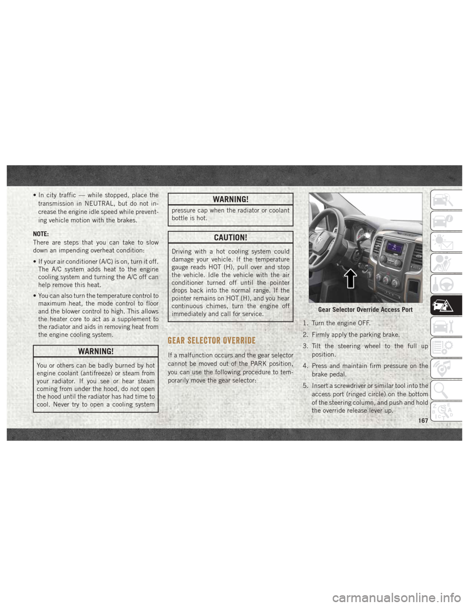
GEAR SELECTOR OVERRIDE
If a malfunction occurs and the gear selector
cannot be moved out of the PARK position,
you can use the following procedure to tem-
porarily move the gear selector: 1. Turn the engine OFF.
2. Firmly apply the parking brake.
3. Tilt the steering wheel to the full up
position.
4. Press and maintain firm pressure on the brake pedal.
5. Insert a screwdriver or similar tool into the access port (ringed circle) on the bottom
of the steering column, and push and hold
the override release lever up.
Gear Selector Override Access Port
167