key battery Ram 4500 Chassis Cab 2018 User Guide
[x] Cancel search | Manufacturer: RAM, Model Year: 2018, Model line: 4500 Chassis Cab, Model: Ram 4500 Chassis Cab 2018Pages: 298, PDF Size: 5.88 MB
Page 15 of 298
• Warranty information
• Crucial driver information and assistance:
• OperatingInstructions • Maintenance
Schedules
• Warranty Information • Emergency
Procedures
• Fluid Level Standards • 911 Contact
and More
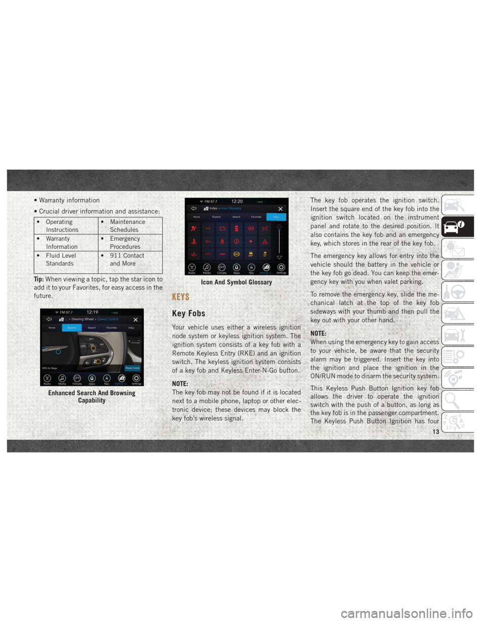
Tip: When viewing a topic, tap the star icon to
add it to your Favorites, for easy access in the
future.
KEYS
Key Fobs
Your vehicle uses either a wireless ignition
node system or keyless ignition system. The
ignition system consists of a key fob with a
Remote Keyless Entry (RKE) and an ignition
switch. The keyless ignition system consists
of a key fob and Keyless Enter-N-Go button.
NOTE:
The key fob may not be found if it is located
next to a mobile phone, laptop or other elec-
tronic device; these devices may block the
key fob’s wireless signal. The key fob operates the ignition switch.
Insert the square end of the key fob into the
ignition switch located on the instrument
panel and rotate to the desired position. It
also contains the key fob and an emergency
key, which stores in the rear of the key fob.
The emergency key allows for entry into the
vehicle should the battery in the vehicle or
the key fob go dead. You can keep the emer-
gency key with you when valet parking.
To remove the emergency key, slide the me-
chanical latch at the top of the key fob
sideways with your thumb and then pull the
key out with your other hand.
NOTE:
When using the emergency key to gain access
to your vehicle, be aware that the security
alarm may be triggered. Insert the key into
the ignition and place the ignition in the
ON/RUN mode to disarm the security system.
This Keyless Push Button Ignition key fob
allows the driver to operate the ignition
switch with the push of a button, as long as
the key fob is in the passenger compartment.
The Keyless Push Button Ignition has four
Enhanced Search And Browsing
Capability
Icon And Symbol Glossary
13
Page 16 of 298
operating positions, three of which are la-
beled and will illuminate when in position.
The three positions are OFF, ACC, and ON/
RUN. The fourth position is START, during
start RUN will illuminate. It also contains the
key fob and an emergency key, which stores
in the rear of the key fob.
The emergency key allows for entry into the
vehicle should the battery in the vehicle or
the key fob go dead. You can keep the emer-
gency key with you when valet parking.
To remove the emergency key, slide the me-
chanical latch on the backside of the key fob
sideways with your thumb and then pull the
key out with your other hand.
NOTE:
• When using the emergency key to gainaccess to your vehicle, be aware that the
security alarm may be triggered. Put the
nose side (side opposite of the emergency
key) of the key fob against the ENGINE
START/STOP button and push to disarm
the security system. • You can insert the double-sided emergency
key into the door lock cylinder with either
side up.
The Remote Keyless Entry system allows you
to lock or unlock all doors, and the tailgate as
well as activate the Panic Alarm from dis-
tances up to approximately 66 ft (20 m)
using a key fob with integrated key. The key
fob does not need to be pointed at the vehicle
to activate the system. Push and release the
lock button on the key fob to lock all doors,
and the tailgate. The turn signal lights will
flash and the horn will chirp to acknowledge
the signal.
NOTE:
Inserting the key fob with integrated key into
the ignition switch disables the system from
responding to any button pushes from that
key fob. Driving at speeds 5 mph (8 km/h)
and above disables the system from respond-
ing to all key fob buttons for all key fobs.
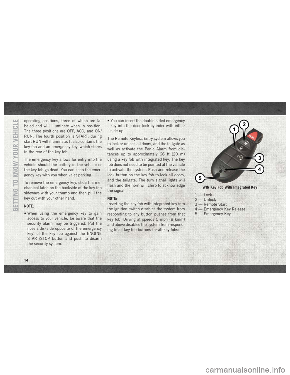
WIN Key Fob With Integrated Key
1 — Lock
2 — Unlock
3 — Remote Start
4 — Emergency Key Release
5 — Emergency Key
GETTING TO KNOW YOUR VEHICLE
14
Page 18 of 298
NOTE:
Changes or modifications not expressly ap-
proved by the party responsible for compli-
ance could void the user’s authority to oper-
ate the equipment.
IGNITION SWITCH
Wireless Ignition Node (WIN) —
If Equipped
The Wireless Ignition Node (WIN) operates
similar to an ignition switch. It has four
operating positions, three with detents and
one that is spring-loaded. The detent posi-
tions are OFF, ACC, and ON/RUN. The START
position is a spring-loaded momentary con-
tact position. When released from the START
position, the switch automatically returns to
the ON/RUN position.
Keyless Push Button Ignition —
If Equipped
This feature allows the driver to operate the
ignition switch with the push of a button as
long as the Remote Keyless Entry key fob is in
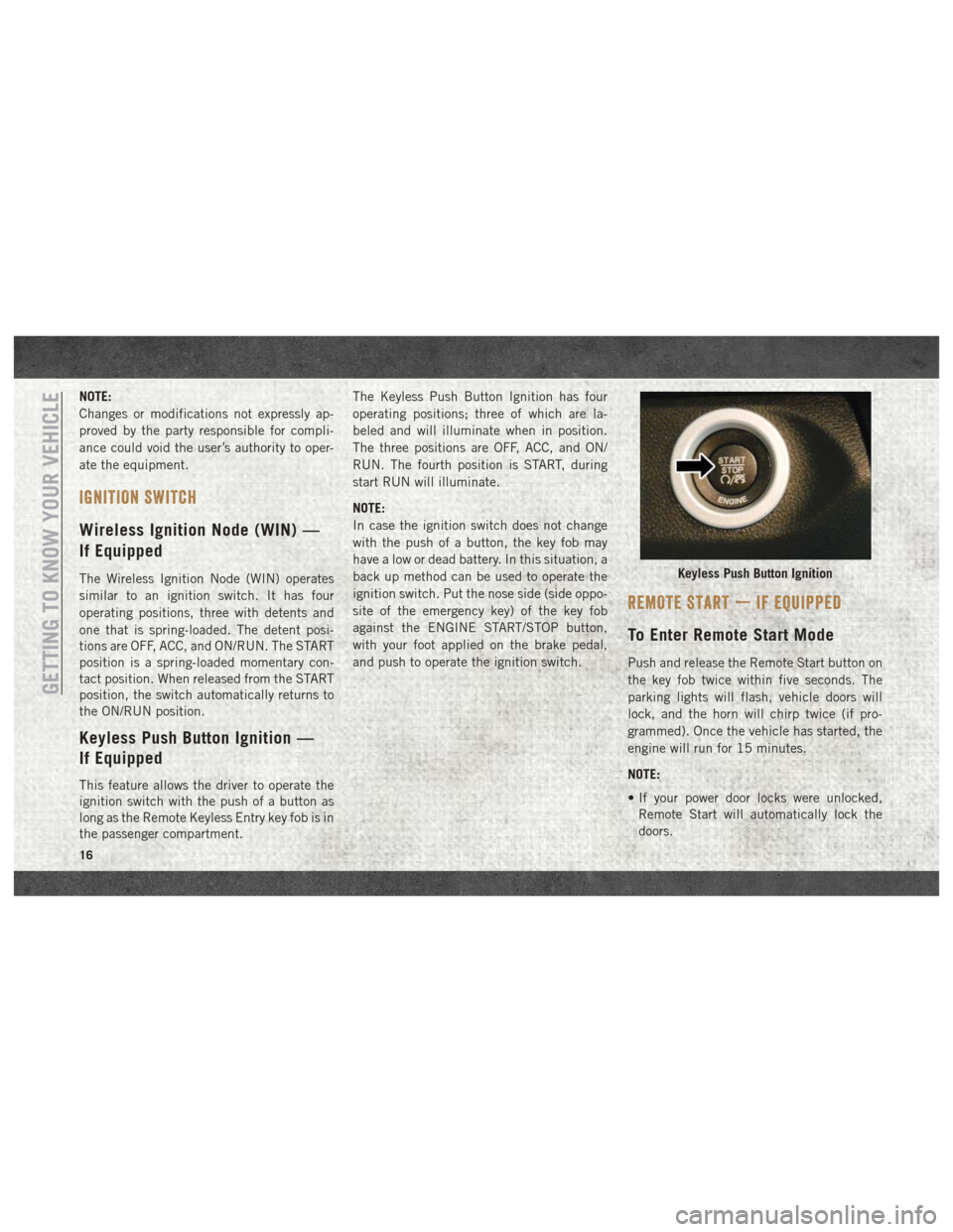
the passenger compartment.The Keyless Push Button Ignition has four
operating positions; three of which are la-
beled and will illuminate when in position.
The three positions are OFF, ACC, and ON/
RUN. The fourth position is START, during
start RUN will illuminate.
NOTE:
In case the ignition switch does not change
with the push of a button, the key fob may
have a low or dead battery. In this situation, a
back up method can be used to operate the
ignition switch. Put the nose side (side oppo-
site of the emergency key) of the key fob
against the ENGINE START/STOP button,
with your foot applied on the brake pedal,
and push to operate the ignition switch.
REMOTE START — IF EQUIPPED
To Enter Remote Start Mode
Push and release the Remote Start button on
the key fob twice within five seconds. The
parking lights will flash, vehicle doors will
lock, and the horn will chirp twice (if pro-
grammed). Once the vehicle has started, the
engine will run for 15 minutes.
NOTE:
• If your power door locks were unlocked,
Remote Start will automatically lock the
doors.
Keyless Push Button Ignition
GETTING TO KNOW YOUR VEHICLE
16
Page 20 of 298
To Arm The System
Follow these steps to arm the vehicle security
alarm:
1. Remove the key from the ignition system(refer to "Starting The Engine" in "Starting
And Operating" for further information).
• For vehicles equipped with Keyless Enter-N-Go — Ignition, make sure the
vehicle ignition system is "OFF."
• For vehicles not equipped with Keyless Enter-N-Go — Ignition, make sure the
vehicle ignition system is "OFF" and
the key is physically removed from the
ignition.
2. Perform one of the following methods to lock the vehicle:
• Push lock button on the interior power door lock switch with the driver and/or
passenger door open.
• Push the lock button on the exterior Passive Entry Door Handle with a valid
key fob available in the same exterior zone (refer to "Keyless Enter- N-Go —
Passive Entry" in "Getting To Know Your
Vehicle" for further information).
• Push the lock button on the key fob.
3. If any doors are open, close them.
The vehicle security alarm will set when you
use the power door locks, or use the key fob to
lock the doors. After all the doors are locked
and closed, the vehicle security light, in the
instrument panel cluster, will flash rapidly for
about 16 seconds to indicate that the alarm
is being set. After the alarm is set, the vehicle
security light will flash at a slower rate to
indicate that the system is armed.
To Disarm The System
The vehicle security alarm can be disarmed
using any of the following methods:
1. Push the unlock button on the key fob.
2. Grasp the Passive Entry Unlock Door Handle with a valid key fob within 5 ft
(1.5 m) of the passive entry door handle.
If equipped, refer to "Keyless Enter-N-Go
— Passive Entry" in "Getting To Know Your
Vehicle" for further information. 3. Cycle the ignition out of the OFF position.
• For vehicles equipped with KeylessEnter-N-Go — Ignition, push the Key-
less Ignition START/STOP button (re-
quires at least one valid key fob in the
vehicle).
• For vehicles not equipped with Keyless Enter-N-Go, insert a valid key into the
ignition switch and turn the key to the
ON position.
The vehicle security alarm is designed to
protect your vehicle. However, you can create
conditions where the system will give you a
false alarm. If one of the previously described
arming sequences has occurred, the vehicle
security alarm will arm regardless of whether
you are in the vehicle or not. If you remain in
the vehicle and open a door, the alarm will
sound. If this occurs, disarm the vehicle
security alarm.
If the vehicle security alarm is armed and the
battery becomes disconnected, the vehicle
security alarm will remain armed when theGETTING TO KNOW YOUR VEHICLE
18
Page 21 of 298
battery is reconnected; the exterior lights will
flash, and the horn will sound. If this occurs,
disarm the vehicle security alarm.
DOORS
Keyless Enter-N-Go — Passive
Entry
The Passive Entry system is an enhancement
to the vehicle’s Remote Keyless Entry system
and a feature of Keyless Enter-N-Go. This
feature allows you to lock and unlock the
vehicle’s door(s) without having to push the
key fob lock or unlock buttons.
NOTE:
•
Refer to “Uconnect Settings” in “Multimedia”
in the Owner’s Manual at
www.mopar.com/
en-us/care/owners-manual.html (U.S.
Residents) or www.owners.mopar.ca
(Canadian Residents) for further information.
• If wearing gloves on your hands, or if it has been raining/snowing on the Passive Entry
door handle, the unlock sensitivity can be
affected, resulting in a slower response
time. • If the vehicle is unlocked by Passive Entry
and no door is opened within 60 seconds,
the vehicle will re-lock and if equipped will
arm the security alarm.
• The vehicles security alarm can be armed/ disarmed by pushing the passive entry key
fob lock/unlock buttons (if equipped).
• The key fob may not be able to be detected by the vehicle passive entry system if it is
located next to a mobile phone, laptop or
other electronic device; these devices may
block the key fob's wireless signal and pre-
vent the passive entry handle from locking/
unlocking the vehicle.
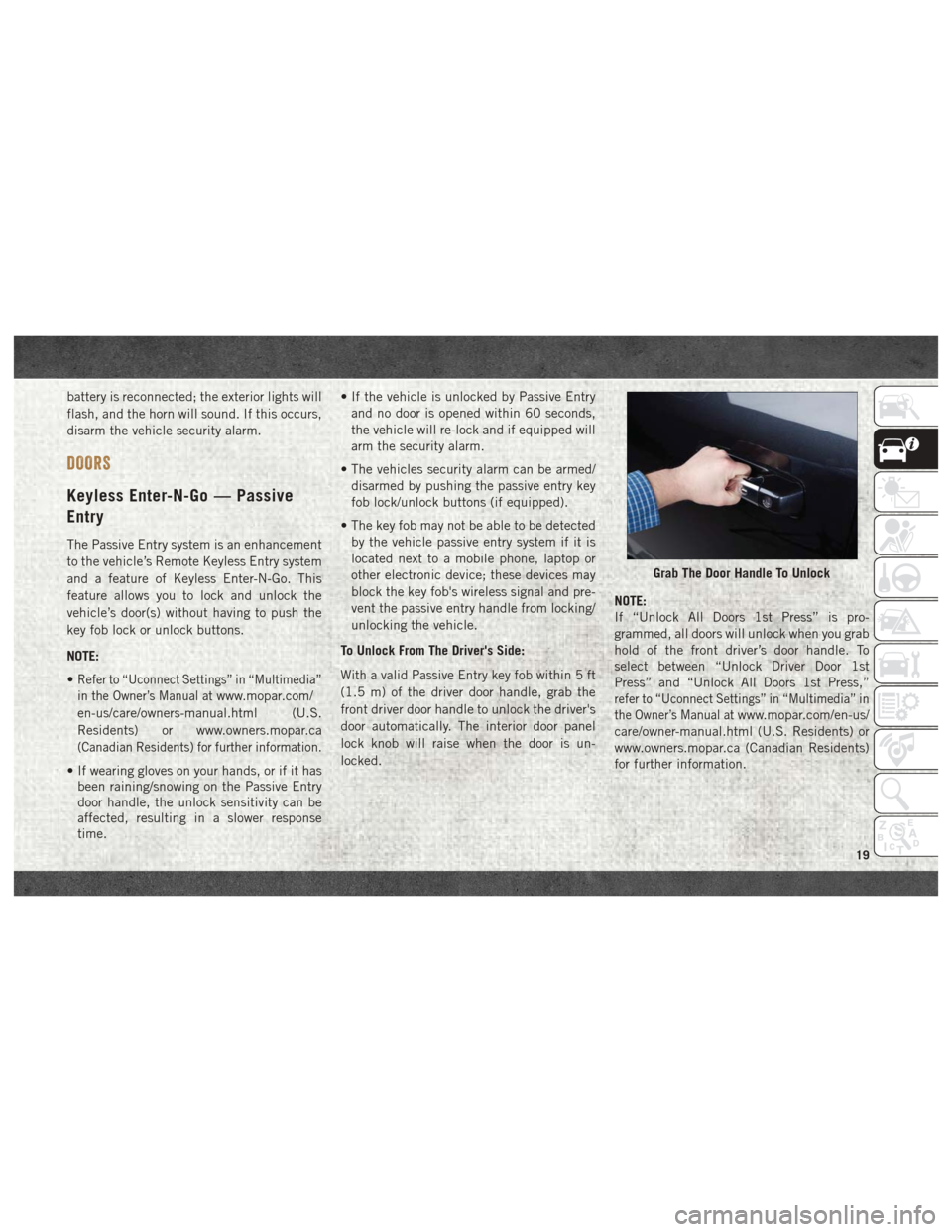
To Unlock From The Driver's Side:
With a valid Passive Entry key fob within 5 ft
(1.5 m) of the driver door handle, grab the
front driver door handle to unlock the driver's
door automatically. The interior door panel
lock knob will raise when the door is un-
locked. NOTE:
If “Unlock All Doors 1st Press” is pro-
grammed, all doors will unlock when you grab
hold of the front driver’s door handle. To
select between “Unlock Driver Door 1st
Press” and “Unlock All Doors 1st Press,”
refer to “Uconnect Settings” in “Multimedia” in
the Owner’s Manual at
www.mopar.com/en-us/
care/owner-manual.html (U.S. Residents) or
www.owners.mopar.ca (Canadian Residents)
for further information.
Grab The Door Handle To Unlock
19
Page 22 of 298
To Unlock From The Passenger Side:
With a valid Passive Entry key fob within 5 ft
(1.5 m) of the passenger door handle, grab
the front passenger door handle to unlock all
doors automatically. The interior door panel
lock knob will raise when the door is un-
locked.
NOTE:
All doors will unlock when the front passen-
ger door handle is grabbed regardless of the
driver’s door unlock preference setting (“Un-
lock Driver Door 1st Press” or “Unlock All
Doors 1st Press”).
Preventing Inadvertent Locking Of Passive Entry
Key Fob In Vehicle:
To minimize the possibility of unintentionally
locking a Passive Entry key fob inside your
vehicle, the Passive Entry system is equipped
with an automatic door unlock feature which
will function if the ignition switch is in the
OFF position.
If one of the vehicle doors is open and the
door panel switch is used to lock the vehicle,
once all open doors have been closed the
vehicle checks the inside and outside of thevehicle for any valid Passive Entry key fobs. If
one of the vehicle's Passive Entry key fobs is
detected inside the vehicle, and no other
valid Passive Entry key fobs are detected
outside the vehicle, the Passive Entry System
automatically unlocks all vehicle doors and
chirps the horn three times (on the third
attempt ALL doors will lock and the Passive
Entry key fob can be locked in the vehicle).
To Lock The Vehicle’s Doors:
With one of the vehicle’s Passive Entry key
fobs within 5 ft (1.5 m) of the driver or
passenger front door handles, push the door
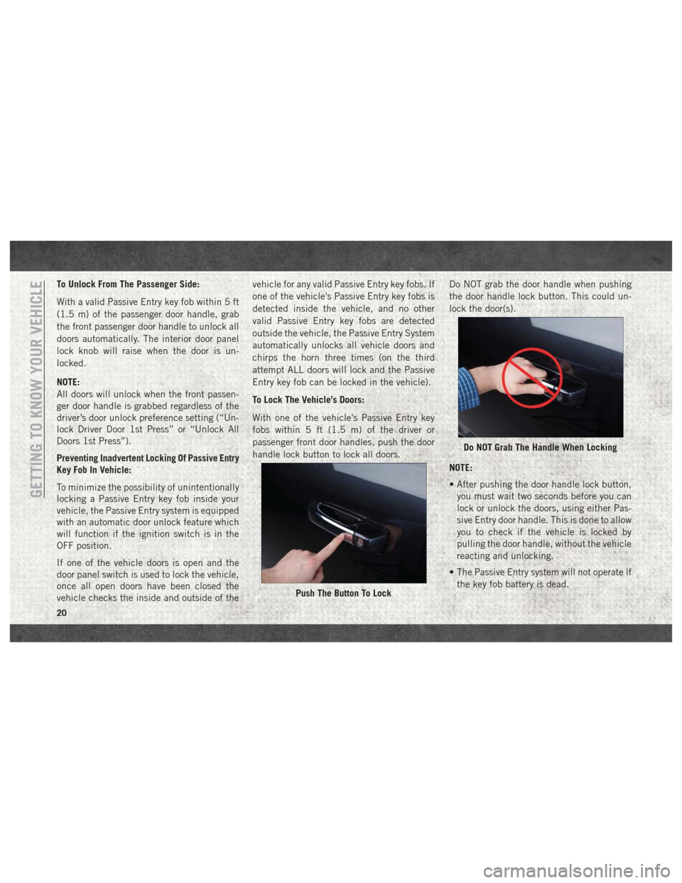
handle lock button to lock all doors.
Do NOT grab the door handle when pushing
the door handle lock button. This could un-
lock the door(s).
NOTE:
• After pushing the door handle lock button,
you must wait two seconds before you can
lock or unlock the doors, using either Pas-
sive Entry door handle. This is done to allow
you to check if the vehicle is locked by
pulling the door handle, without the vehicle
reacting and unlocking.
• The Passive Entry system will not operate if the key fob battery is dead.
Push The Button To Lock
Do NOT Grab The Handle When Locking
GETTING TO KNOW YOUR VEHICLE
20
Page 48 of 298
• The HomeLink buttons that are located inthe overhead console or sunvisor designate
the three different HomeLink channels.
• To operate HomeLink, push and release any of the programmed HomeLink buttons.
These buttons will activate the devices they
are programmed to with each press of the
corresponding HomeLink button.
Before You Begin Programming
HomeLink
For efficient programming and accurate
transmission of the radio-frequency signal, it
is recommended that a new battery be placed
in the hand-held transmitter of the device
that is being programmed to the HomeLink
system. Make sure your hand-held transmit-
ter is programmed to activate the device you
are trying to program your HomeLink button
to.
Ensure that your vehicle is parked outside of
the garage before you begin programming.
It is recommended that you erase all the
channels of your HomeLink before you use it
for the first time. If you have any problems, or require assis-
tance, please call toll-free 1-800-355-3515
or, on the Internet at HomeLink.com for in-
formation or assistance.
Erasing All The HomeLink
Channels
To erase the channels, follow this procedure:
1. Place the ignition switch into the ON/RUN
position.
NOTE:
For vehicle’s equipped with Keyless
Enter-N-Go, place the ignition in the RUN
position with the Engine ON. Make sure to
program HomeLink with the vehicle out-
side of the garage, or with the garage door
open at all times.
2. Push and hold the two outside HomeLink buttons (I and III) for up to 20 seconds, or
until the instrument cluster display
switches from the “Clearing Channels”
message to the “Channels Cleared”
message. NOTE:
Erasing all channels should only be per-
formed when programming HomeLink for the
first time. Do not erase channels when pro-
gramming additional buttons.
Identifying Whether You Have A
Rolling Code Or Non-Rolling Code
Device
Before programming a device to one of your
HomeLink buttons, you must determine
whether the device has a rolling code or
non-rolling code.
Rolling Code Devices
To determine if your device has a rolling code,
a good indicator is its manufacturing date.
Typically, devices manufactured after
1995 have rolling codes. A device with a
rolling code will also have a “LEARN” or
“TRAIN” button located where the antenna is
attached to the device. The button may not
be immediately visible when looking at the
device. The name and color of the button may
vary slightly by manufacturer.
GETTING TO KNOW YOUR VEHICLE
46
Page 51 of 298
NOTE:
For vehicle’s equipped with Keyless Enter-
N-Go, place the ignition in the RUN posi-
tion with the Engine ON. Make sure to
program HomeLink with the vehicle out-
side of the garage, or with the garage door
open at all times.
2. Push and hold the desired HomeLink but- ton until the instrument cluster display
shows the “CHANNEL # TRAINING” mes-
sage. Do not release the button.
3. Without releasing the button, proceed with
Step 2 in “Programming HomeLink To A
Garage Door Opener” and follow all re-
maining steps.
General Information
The following regulatory statement applies to
all Radio Frequency (RF) devices equipped in
this vehicle:
This device complies with Part 15 of the FCC
Rules and with Industry Canada license-
exempt RSS standard(s). Operation is sub-
ject to the following two conditions:
1. This device may not cause harmful inter- ference, and 2. This device must accept any interference
received, including interference that may
cause undesired operation.
NOTE:
Changes or modifications not expressly ap-
proved by the party responsible for compli-
ance could void the user’s authority to oper-
ate the equipment.
INTERNAL EQUIPMENT
Electrical Power Outlets
The auxiliary 12 Volt (13 Amp) power outlets
can provide power for in-cab accessories de-
signed for use with the standard “cigar
lighter” plug. The 12 Volt power outlets and
USB Port (Charge Only) have a cap attached
to the outlet indicating “12V DC,” together
with either a key symbol, battery symbol, or
USB symbol.
A key symbol indicates that the key must be
in the ON/RUN or ACC positions for the outlet
to provide power. The battery symbol indi-
cates that the outlet is connected to the
battery, and can provide power at all times. NOTE:
To ensure proper operation, a Mopar knob
and element must be used.
CAUTION!
• Do not exceed the maximum power of
160 Watts (13 Amps) at 12 Volts. If the
160 Watts (13 Amps) power rating is
exceeded, the fuse protecting the sys-
tem will need to be replaced.
• Power outlets are designed for accessory
plugs only. Do not insert any other object
in the power outlets as this will damage
the outlet and blow the fuse. Improper
use of the power outlet can cause dam-
age not covered by your New Vehicle
Limited Warranty.
49
Page 159 of 298
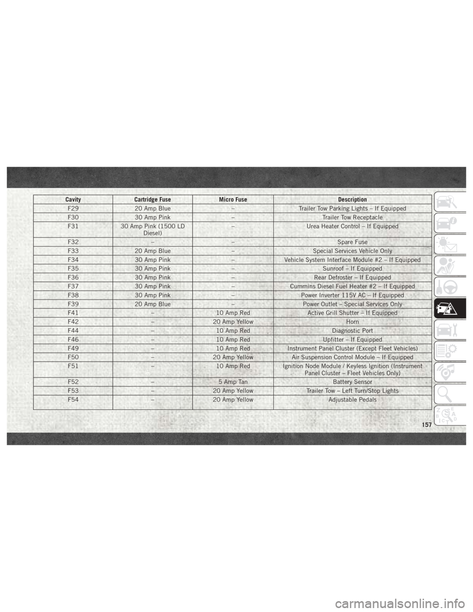
CavityCartridge Fuse Micro Fuse Description
F29 20 Amp Blue –Trailer Tow Parking Lights – If Equipped
F30 30 Amp Pink –Trailer Tow Receptacle
F31 30 Amp Pink (1500 LD
Diesel) –
Urea Heater Control – If Equipped
F32 –– Spare Fuse
F33 20 Amp Blue –Special Services Vehicle Only
F34 30 Amp Pink –Vehicle System Interface Module #2 – If Equipped
F35 30 Amp Pink –Sunroof – If Equipped
F36 30 Amp Pink –Rear Defroster – If Equipped
F37 30 Amp Pink –Cummins Diesel Fuel Heater #2 – If Equipped
F38 30 Amp Pink –Power Inverter 115V AC – If Equipped
F39 20 Amp Blue –Power Outlet – Special Services Only
F41 –10 Amp Red Active Grill Shutter – If Equipped
F42 –20 Amp Yellow Horn
F44 –10 Amp Red Diagnostic Port
F46 –10 Amp Red Upfitter – If Equipped
F49 –10 Amp Red Instrument Panel Cluster (Except Fleet Vehicles)
F50 –20 Amp Yellow Air Suspension Control Module – If Equipped
F51 –10 Amp Red Ignition Node Module / Keyless Ignition (Instrument
Panel Cluster – Fleet Vehicles Only)
F52 –5 Amp Tan Battery Sensor
F53 –20 Amp Yellow Trailer Tow – Left Turn/Stop Lights
F54 –20 Amp Yellow Adjustable Pedals
157
Page 171 of 298

TOWING A DISABLED VEHICLE
This section describes procedures for towing
a disabled vehicle using a commercial towing
service. If the transmission and drivetrain areoperable, disabled vehicles may also be
towed as described under “Recreational Tow-
ing” in the “Starting And Operating” section.
Towing Condition
Wheels OFF The
Ground 2WD Models
4WD Models
Flat Tow NONE If transmission is operable:
• Transmission in
NEUTRAL
• 30 mph (48 km/h) max speed
• 15 miles (24 km) maxdistance See instructions in “Recreational Towing” under
“Starting And Operating”
• Auto Transmission in
PARK
• Manual Transmission in gear ( NOTNEUTRAL)
• Transfer Case in NEUTRAL
•Towinforward direction
Wheel Lift Or Dolly Tow Front
NOT ALLOWED
Rear OK NOT ALLOWED
Flatbed ALL
BEST METHOD BEST METHOD
Proper towing or lifting equipment is required
to prevent damage to your vehicle. Use only
tow bars and other equipment designed for
this purpose, following equipment manufac-
turer’s instructions. Use of safety chains is
mandatory. Attach a tow bar or other towing
device to main structural members of thevehicle, not to bumpers or associated brack-
ets. State and local laws regarding vehicles
under tow must be observed.
If you must use the accessories (wipers, de-
frosters, etc.) while being towed, the ignition
must be in the ON/RUN mode, not the ACC
mode.If the key fob is unavailable or the vehicle's
battery is discharged, refer to “Gear Selector
Override” in this section for instructions on
shifting the automatic transmission out of
PARK for towing.
169