power steering Ram 4500 Chassis Cab 2018 User Guide
[x] Cancel search | Manufacturer: RAM, Model Year: 2018, Model line: 4500 Chassis Cab, Model: Ram 4500 Chassis Cab 2018Pages: 298, PDF Size: 5.88 MB
Page 11 of 298
GETTING TO KNOW YOUR VEHICLE
VEHICLE USER GUIDE — IF EQUIPPED .11
KEYS......................13
Key Fobs ....................13
IGNITION SWITCH ..............16
Wireless Ignition Node (WIN) —
If Equipped...................16
Keyless Push Button Ignition —
If Equipped ...................16
REMOTE START — IF EQUIPPED .....16
To Enter Remote Start Mode........16
To Exit Remote Start Mode Without
Driving The Vehicle .............17
To Exit Remote Start Mode And Drive
The Vehicle ...................17
General Information .............17
VEHICLE SECURITY ALARM ........17
To Arm The System..............18
To Disarm The System ............18
DOORS.....................19
Keyless Enter-N-Go — Passive Entry . . .19
SEATS .....................21
Driver Memory Seat — If Equipped ....21
Heated Seats ..................24
HEAD RESTRAINTS ..............26
Front Head Restraint Adjustment .....26
Rear Head Restraint Adjustment ......26
Front Head Restraint Removal .......27
Rear Head Restraint Removal ........27
STEERING WHEEL..............28
Tilt Steering Column .............28
Heated Steering Wheel — If Equipped . .28
DRIVER ADJUSTABLE PEDALS —
IF EQUIPPED .................29
MIRRORS ...................30
Power Folding Outside Mirrors For Standard
And Trailer Tow — If Equipped .......30
EXTERIOR LIGHTS..............31
Headlight Switch...............31
Headlights ...................32
Multifunction Lever .............32
High/Low Beam Switch ...........32Automatic High Beam Headlamp Control —
If Equipped
..................32
Automatic Headlights — If Equipped . .33
Parking Lights And Panel Lights ......34
Headlights On With Wipers (Available
With Automatic Headlights Only) ......34
Turn Signals ..................34
Lane Change Assist — If Equipped ....34
Cargo Light ..................34
WINDSHIELD WIPERS AND WASHERS .34
Windshield Wipers ..............34
Rain Sensing Wipers — If Equipped . . .35
CLIMATE CONTROLS .............37
Automatic Climate Controls With A
Touchscreen..................37
Climate Control Functions ..........42
Automatic Temperature Control (ATC) —
If Equipped ...................43
Operating Tips .................44
HOOD......................44
To Open The Hood ..............44
To Close The Hood ..............45
GETTING TO KNOW YOUR VEHICLE
9
Page 33 of 298
• The mirrors shake and vibrate at normaldriving speeds.
To Reset The Power Folding Mirrors:
1. Using the power folding mirror switch, move the mirror to its full forward
position.
2. Using the power folding mirror switch, move the mirror to the full retract position
(this may require multiple button
pushes). This resets them to their normal
position.
NOTE:
• The power fold mirrors are designed to operate while the vehicle is stationary or
traveling at moderate speeds. If you at-
tempt to power fold the mirrors at high
speeds they may not fully open or close. You
should slow down to a moderate speed and
complete the operation.
• When pushing the power fold button 10 or more times in one minute the system shuts
down for one minute to protect the motors
from over heating.EXTERIOR LIGHTS
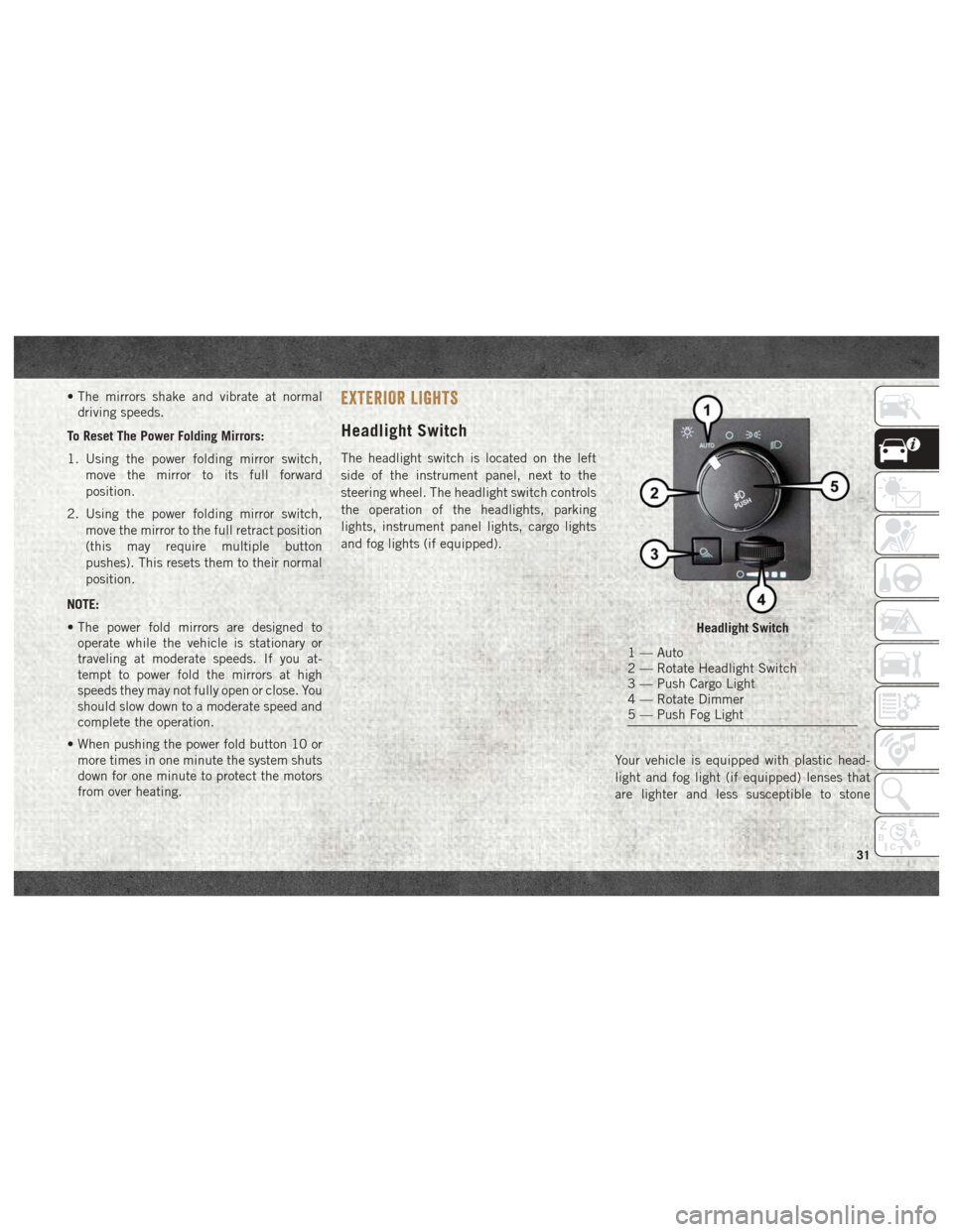
Headlight Switch
The headlight switch is located on the left
side of the instrument panel, next to the
steering wheel. The headlight switch controls
the operation of the headlights, parking
lights, instrument panel lights, cargo lights
and fog lights (if equipped).
Your vehicle is equipped with plastic head-
light and fog light (if equipped) lenses that
are lighter and less susceptible to stone
Headlight Switch
1 — Auto
2 — Rotate Headlight Switch
3 — Push Cargo Light
4 — Rotate Dimmer
5 — Push Fog Light
31
Page 47 of 298

1. Pull the hood release lever located belowthe steering wheel at the base of the
instrument panel.
2. Reach into the opening beneath the cen- ter of the hood and push the safety latch
lever to the left to release it, before raising
the hood.
To Close The Hood
Lower the hood to approximately 12 inches
(30 cm) from the engine compartment and
drop it. Make sure that the hood is completely
closed.
WARNING!
Be sure the hood is fully latched before
driving your vehicle. If the hood is not fully
latched, it could open when the vehicle is
in motion and block your vision. Failure to
follow this warning could result in serious
injury or death.
CAUTION!
To prevent possible damage, do not slam
the hood to close it. Use a firm downward
push at the front center of the hood to
ensure that both latches engage.
UNIVERSAL GARAGE DOOR OPENER
(HOMELINK)
• HomeLink replaces up to three hand-held
transmitters that operate devices such as
garage door openers, motorized gates,
lighting or home security systems. The
HomeLink unit is powered by your vehicles
12 Volt battery.
HomeLink Buttons
45
Page 65 of 298
— Electric Power Steering Fault
Warning Light
This light will turn on when there's a fault
with the EPS (Electric Power Steering) sys-
tem. Refer to “Power Steering” in “Starting
And Operating” in the Owner’s Manual at
https://www.mopar.com/en-us/care/
owners-manual.html (U.S. Residents) or
www.owners.mopar.ca (Canadian Residents)
for further information.
WARNING!
Continued operation with reduced assist
could pose a safety risk to yourself and
others. Service should be obtained as soon
as possible.
— Engine Coolant Temperature
Warning Light
This light warns of an overheated engine
condition. If the engine coolant temperature
is too high, this indicator will illuminate and a
single chime will sound. If the temperature
reaches the upper limit, a continuous chime
will be sound for four minutes or until the
engine is able to cool: whichever comes first. If the light turns on while driving, safely pull
over and stop the vehicle. If the A/C system is
on, turn it off. Also, shift the transmission
into NEUTRAL and idle the vehicle. If the
temperature reading does not return to nor-
mal, turn the engine off immediately and call
for service. Refer to “If Your Engine Over-
heats” in “In Case Of Emergency” for further
information.
— Oil Pressure Warning Light
This light indicates low engine oil pressure. If
the light turns on while driving, stop the
vehicle and shut off the engine as soon as
possible. A chime will sound when this light
turns on.
Do not operate the vehicle until the cause is
corrected. This light does not indicate how
much oil is in the engine. The engine oil level
must be checked under the hood.
— Oil Temperature Warning Light
This telltale indicates engine oil temperature
is high. If the light turns on while driving,
stop the vehicle and shut off the engine as
soon as possible. Wait for oil temperature to
return to normal levels.
— Trailer Brake Disconnected
Warning Light
This telltale is on when the Trailer Brake has
been disconnected.
— Vehicle Security Warning Light —
If Equipped
This light will flash at a fast rate for approxi-
mately 15 seconds when the vehicle security
alarm is arming, and then will flash slowly
until the vehicle is disarmed.
Yellow Warning Lights
— Engine Check/Malfunction
Indicator Warning Light (MIL)
The Engine Check/Malfunction Indicator
Light (MIL) is a part of an Onboard Diagnostic
System called OBD II that monitors engine
and automatic transmission control systems.
The light will illuminate when the ignition is
in the ON/RUN position before engine start.
If the bulb does not come on when turning
the ignition switch from OFF to ON/RUN,
have the condition checked promptly.
63
Page 90 of 298

ON/RUN position. If the ignition switch is in
the OFF position or in the ACC position, the
air bag system is not on and the air bags will
not inflate.
The ORC contains a backup power supply
system that may deploy the air bag system
even if the battery loses power or it becomes
disconnected prior to deployment.
The ORC turns on the Air Bag Warning Light
in the instrument panel for approximately
four to eight seconds for a self-check when
the ignition switch is first in the ON/RUN
position. After the self-check, the Air Bag
Warning Light will turn off. If the ORC detects
a malfunction in any part of the system, it
turns on the Air Bag Warning Light, either
momentarily or continuously. A single chime
will sound to alert you if the light comes on
again after initial startup.
The ORC also includes diagnostics that will
illuminate the instrument panel Air Bag
Warning Light if a malfunction is detected
that could affect the air bag system. The
diagnostics also record the nature of the
malfunction. While the air bag system isdesigned to be maintenance free, if any of
the following occurs, have an authorized
dealer service the air bag system immedi-
ately.
• The Air Bag Warning Light does not come
on during the four to eight seconds when
the ignition switch is first in the ON/RUN
position.
• The Air Bag Warning Light remains on after the four to eight-second interval.
• The Air Bag Warning Light comes on inter- mittently or remains on while driving.
NOTE:
If the speedometer, tachometer, or any en-
gine related gauges are not working, the Oc-
cupant Restraint Controller (ORC) may also
be disabled. In this condition the air bags
may not be ready to inflate for your protec-
tion. Have an authorized dealer service the
air bag system immediately.WARNING!
Ignoring the Air Bag Warning Light in your
instrument panel could mean you won’t
have the air bag system to protect you in a
collision. If the light does not come on as a
bulb check when the ignition is first
turned on, stays on after you start the
vehicle, or if it comes on as you drive, have
an authorized dealer service the air bag
system immediately.
Front Air Bags
This vehicle has front air bags and lap/
shoulder belts for both the driver and front
passenger. The front air bags are a supple-
ment to the seat belt restraint systems. The
driver front air bag is mounted in the center
of the steering wheel. The passenger front air
bag is mounted in the instrument panel,
above the glove compartment. The words
“SRS AIRBAG” or “AIRBAG” are embossed
on the air bag covers.
SAFETY
88
Page 135 of 298

the front and rear wheels to rotate at the same
speed. This range provides additional trac-
tion and maximum pulling power for loose,
slippery road surfaces only. Do not exceed
25 mph (40 km/h).
NEUTRAL (N)
Neutral — This range disengages both the
front and rear driveshafts from the pow-
ertrain. To be used for flat towing behind
another vehicle. Refer to “Recreational Tow-
ing” in this section for further information.
WARNING!
You or others could be injured or killed if
you leave the vehicle unattended with the
transfer case in the NEUTRAL position
without first fully engaging the parking
brake. The transfer case NEUTRAL posi-
tion disengages both the front and rear
drive shafts from the powertrain and will
allow the vehicle to roll, even if the trans-
mission is in PARK. The parking brake
should always be applied when the driver
is not in the vehicle.This electronically shifted transfer case is
designed to be driven in the two-wheel drive
position (2WD) for normal street and highway
conditions on dry, hard surfaced roads.
When additional traction is required, the
transfer case 4WD LOCK and 4WD LOW po-
sitions can be used to maximize torque to the
front driveshaft, forcing the front and rear
wheels to rotate at the same speed. This is
accomplished by rotating the 4WD Control
Switch to the desired position.
Refer to “Shifting Procedure” in the “Start-
ing And Operating” section of your Owner’s
Manual
locatedat
www.mopar.com/en-us/care/owners-manual.html
(U.S. Residents) or www.owners.mopar.ca
(Canadian Residents) for specific shifting in-
structions.
SPEED CONTROL
When engaged, the Speed Control takes over
accelerator operations at speeds greater than
25 mph (40 km/h). The Speed Control buttons are located on the
right side of the steering wheel.
Speed Control Buttons
1 — Push Cancel
2 — Push On/Off
3 — Push Resume/Accel
4 — Push Set/Decel
133
Page 147 of 298
GAIN Adjustment Buttons (+/-)
Pushing these buttons will adjust the brake
control power output to the trailer brakes in
0.5 increments. The GAIN setting can be
increased to a maximum of 10 or decreased
to a minimum of 0 (no trailer braking).
GAIN
The GAIN setting is used to set the trailer
brake control for the specific towing condi-
tion and should be changed as towing condi-
tions change. Changes to towing conditions
include trailer load, vehicle load, road condi-
tions and weather.
Adjusting GAIN
NOTE:
This should only be performed in a traffic free
environment at speeds of approximately 20–
25 mph (30–40 km/h).
1. Make sure the trailer brakes are in goodworking condition, functioning normally
and properly adjusted. See your trailer
dealer if necessary. 2. Hook up the trailer and make the electri-
cal connections according to the trailer
manufacturer's instructions.
3. When a trailer with electric/EOH brakes is plugged in, the trailer connected message
should appear in the instrument cluster
display (if the connection is not recog-
nized by the ITBM, braking functions will
not be available), the GAIN setting will
illuminate and the correct type of trailer
must be selected from the instrument
cluster display options.
4. Push the UP or DOWN button on the steering wheel until “TRAILER TOW” ap-
pears on the screen.
5. Push the RIGHT arrow on the steering wheel to enter “TRAILER TOW”.
6. Push the UP or DOWN buttons until the Trailer Brake Type appears on the screen. 7. Push the RIGHT arrow and then push the
UP or DOWN buttons until the proper
Trailer Brake Type appears on the screen.
8. In a traffic-free environment, tow the trailer on a dry, level surface at a speed of
20–25 mph (30–40 km/h) and squeeze
the manual brake control lever
completely.
9. If the trailer wheels lockup (indicated by squealing tires), reduce the GAIN setting;
if the trailer wheels turn freely, increase
the GAIN setting.
Repeat steps 8 and 9 until the GAIN setting
is at a point just below trailer wheel lockup. If
towing a heavier trailer, trailer wheel lockup
may not be attainable even with the maxi-
mum GAIN setting of 10.
145
Page 157 of 298

FUSES
WARNING!
• When replacing a blown fuse, always usean appropriate replacement fuse with
the same amp rating as the original fuse.
Never replace a fuse with another fuse of
higher amp rating. Never replace a
blown fuse with metal wires or any other
material. Do not place a fuse inside a
circuit breaker cavity or vice versa. Fail-
ure to use proper fuses may result in
serious personal injury, fire and/or prop-
erty damage.
WARNING!
• Before replacing a fuse, make sure thatthe ignition is off and that all the other
services are switched off and/or disen-
gaged.
• If the replaced fuse blows again, contact
an authorized dealer.
• If a general protection fuse for safety
systems (air bag system, braking sys-
tem), power unit systems (engine sys-
tem, transmission system) or steering
system blows, contact an authorized
dealer.
Power Distribution Center
The Power Distribution Center is located in
the engine compartment near the battery.
This center contains cartridge fuses, micro
fuses, relays, and circuit breakers. A descrip-
tion of each fuse and component may be
stamped on the inside cover, otherwise the
cavity number of each fuse is stamped on the
inside cover that corresponds to the following
chart.
Cavity Cartridge Fuse Micro Fuse Description
F01 80 Amp Black –Rad Fan Control Module – If Equipped
F03 60 Amp Yellow –Rad Fan – If Equipped
F05 40 Amp Green –Compressor for Air Suspension – If Equipped
F06 40 Amp Green –Antilock Brakes/Electronic Stability Control Pump
F07 40 Amp Green – Starter Solenoid
F08 20 Amp Blue (1500 LD/
Cummins Diesel) –
Emissions Diesel – If Equipped
155
Page 161 of 298

CavityCartridge Fuse Micro Fuse Description
F78 –10 Amp Red Engine Control Module / Electric Power Steering
F79 –15 Amp Blue Clearance Lights
F80 –10 Amp Red Universal Garage Door Opener / Compass
F81 –20 Amp Yellow Trailer Tow Right Turn / Stop Lights
F82 –10 Amp Red Steering Column Control Module / Cruise Control
F84 –15 Amp Blue Switch Bank / Instrument Cluster
F85 –10 Amp Red Airbag Module
F86 –10 Amp Red Airbag Module
F87 –10 Amp Red Air Suspension – If Equipped / Trailer Tow / Steering Col-
umn Control Module
F88 –15 Amp Blue Instrument Panel Cluster
F90/F91 –20 Amp Yellow Power Outlet (Rear Seats) Customer Selectable
F93 –20 Amp Yellow Cigar Lighter
F94 –10 Amp Red Shifter / Transfer Case Module
F95 –10 Amp Red Rear Camera / Park Assist
F96 –10 Amp Red Rear Seat Heater Switch
F97 –25 Amp Clear Rear Heated Seats & Heated Steering Wheel – If
Equipped
F98 –25 Amp Clear Front Heated Seats – If Equipped
F99 –10 Amp Red Climate Control
F100 –10 Amp Red Upfitters – If Equipped
F101 –15 Amp Blue Electrochromatic Mirror / Smart High Beams – If
Equipped
F104 –20 Amp Yellow Power Outlets (Instrument Panel / Center Console)
159
Page 176 of 298
SCHEDULED SERVICING — GASOLINE
ENGINE
Your vehicle is equipped with an automatic
oil change indicator system. The oil change
indicator system will remind you that it is
time to take your vehicle in for scheduled
maintenance.
Based on engine operation conditions, the oil
change indicator message will illuminate.
This means that service is required for your
vehicle. Operating conditions such as fre-
quent short-trips, trailer tow, extremely hot or
cold ambient temperatures, and E85 fuel
usage will influence when the “Oil Change
Required” message is displayed. Severe Op-
erating Conditions can cause the change oil
message to illuminate as early as
3,500 miles (5,600 km) since last reset.
Have your vehicle serviced as soon as pos-
sible, within the next 500 miles (805 km).
Your authorized dealer will reset the oil
change indicator message after completing
the scheduled oil change. If a scheduled oil
change is performed by someone other than
your authorized dealer, the message can bereset by referring to the steps described under
“Warning And Indicator Lights” or “Instru-
ment Cluster Display” in “Getting To Know
Your Instrument Panel” in your Owner’s
Manual at
www.mopar.com/en-us/care/
owner-manual.html (U.S. Residents) or
www.owners.mopar.ca (Canadian Residents)
for further information.
Gasoline Engines:
Under no circumstances should oil change
intervals exceed 8,000 miles (13,000 km),
twelve months or 350 hours of engine run
time, whichever comes first. The 350 hours
of engine run or idle time is generally only a
concern for fleet customers.
Severe Duty:
Change Engine Oil at 4,000 miles
(6,500 km) or 350 hours of engine run time
if the vehicle is operated in a dusty and off
road environment or is operated predomi-
nately at idle or very low engine RPM’s. This
type of vehicle use is considered Severe Duty. Once A Month Or Before A Long Trip:
• Check engine oil level
• Check windshield washer fluid level
• Check the tire inflation pressures and look
for unusual wear or damage
• Check the fluid levels of the coolant reser- voir, brake master cylinder, power steering
and automatic transmission, and fill as
needed
• Check function of all interior and exterior lights
SERVICING AND MAINTENANCE
174