instrument cluster Ram 4500 Chassis Cab 2018 User Guide
[x] Cancel search | Manufacturer: RAM, Model Year: 2018, Model line: 4500 Chassis Cab, Model: Ram 4500 Chassis Cab 2018Pages: 298, PDF Size: 5.88 MB
Page 8 of 298
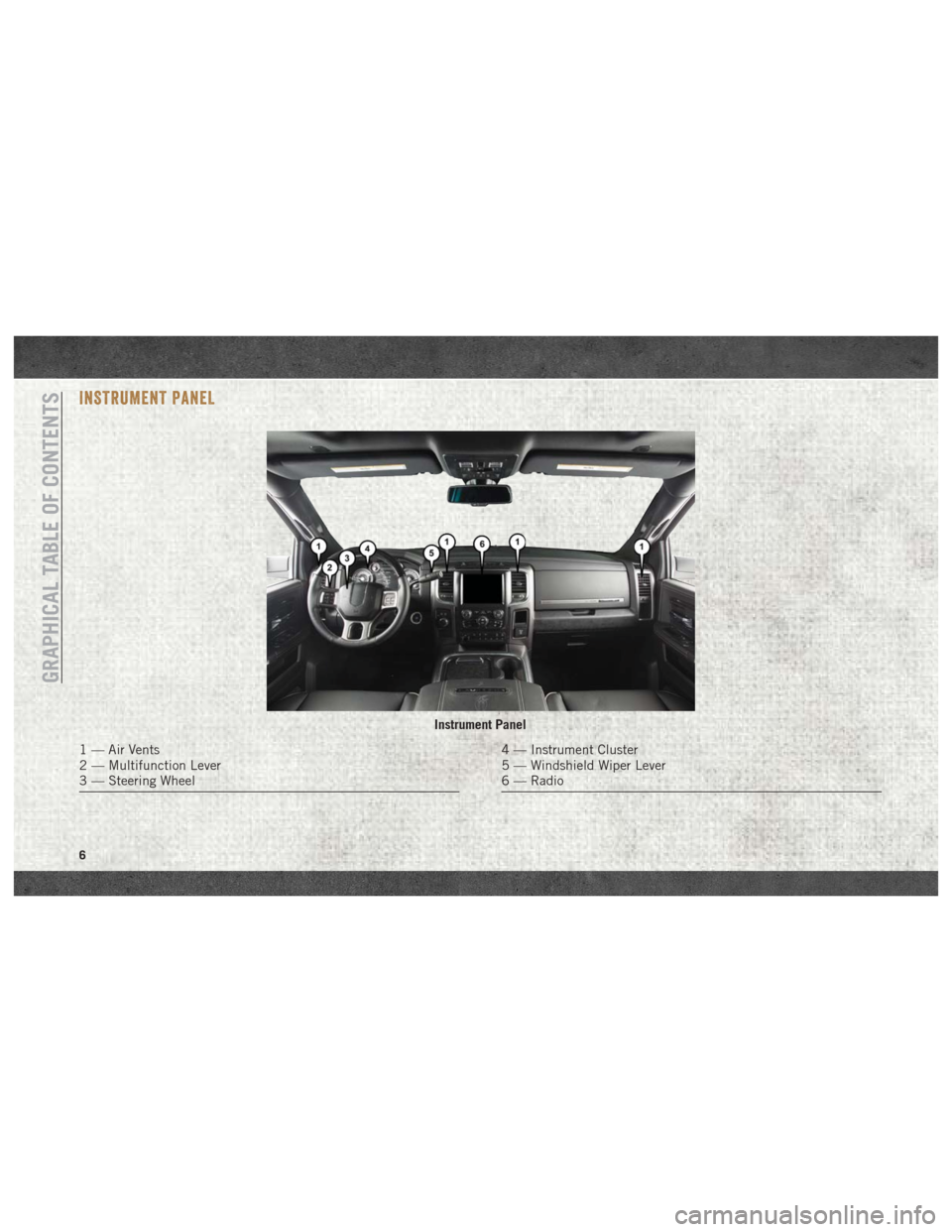
INSTRUMENT PANEL
Instrument Panel
1 — Air Vents
2 — Multifunction Lever
3 — Steering Wheel4 — Instrument Cluster
5 — Windshield Wiper Lever
6 — Radio
GRAPHICAL TABLE OF CONTENTS
6
Page 17 of 298
To Unlock The Doors And Tailgate
Push and release the unlock button on the
key fob once to unlock the driver’s door. Push
the unlock button twice within five seconds
to unlock all doors, and the tailgate. The turnsignal lights will flash to acknowledge the
unlock signal. The illuminated entry system
will also turn on.
NOTE:
The instrument cluster display or Uconnect
Settings are setup for driver door first, other-
wise this will unlock all doors.
To Lock The Doors And Tailgate
Push and release the lock button on the key
fob to lock all doors, and the tailgate. The
turn signal lights will flash and the horn will
chirp to acknowledge the signal.
Using The Panic Alarm
To turn the Panic Alarm feature on or off,
push the Panic button on the key fob. When
the Panic Alarm is activated, the turn signals
will flash, the horn will pulse on and off, and
the interior lights will turn on.
The Panic Alarm will stay on for three min-
utes unless you turn it off by either pushing
the Panic button a second time or drive the
vehicle at a speed of 15 mph (24 km/h) or
greater.
NOTE:
• The interior lights will turn off if you place
the ignition in the ACC or ON/RUN position
while the Panic Alarm is activated. How-
ever, the exterior lights and horn will remain
on.
• You may need to be less than 35 ft (11 m) from the vehicle when using the key fob to
turn off the Panic Alarm due to the radio
frequency noises emitted by the system.
General Information
The following regulatory statement applies to
all radio frequency (RF) devices equipped in
this vehicle:
This device complies with Part 15 of the FCC
Rules and with Industry Canada license-
exempt RSS standard(s). Operation is sub-
ject to the following two conditions:
1. This device may not cause harmful inter-
ference, and
2. This device must accept any interference received, including interference that may
cause undesired operation.
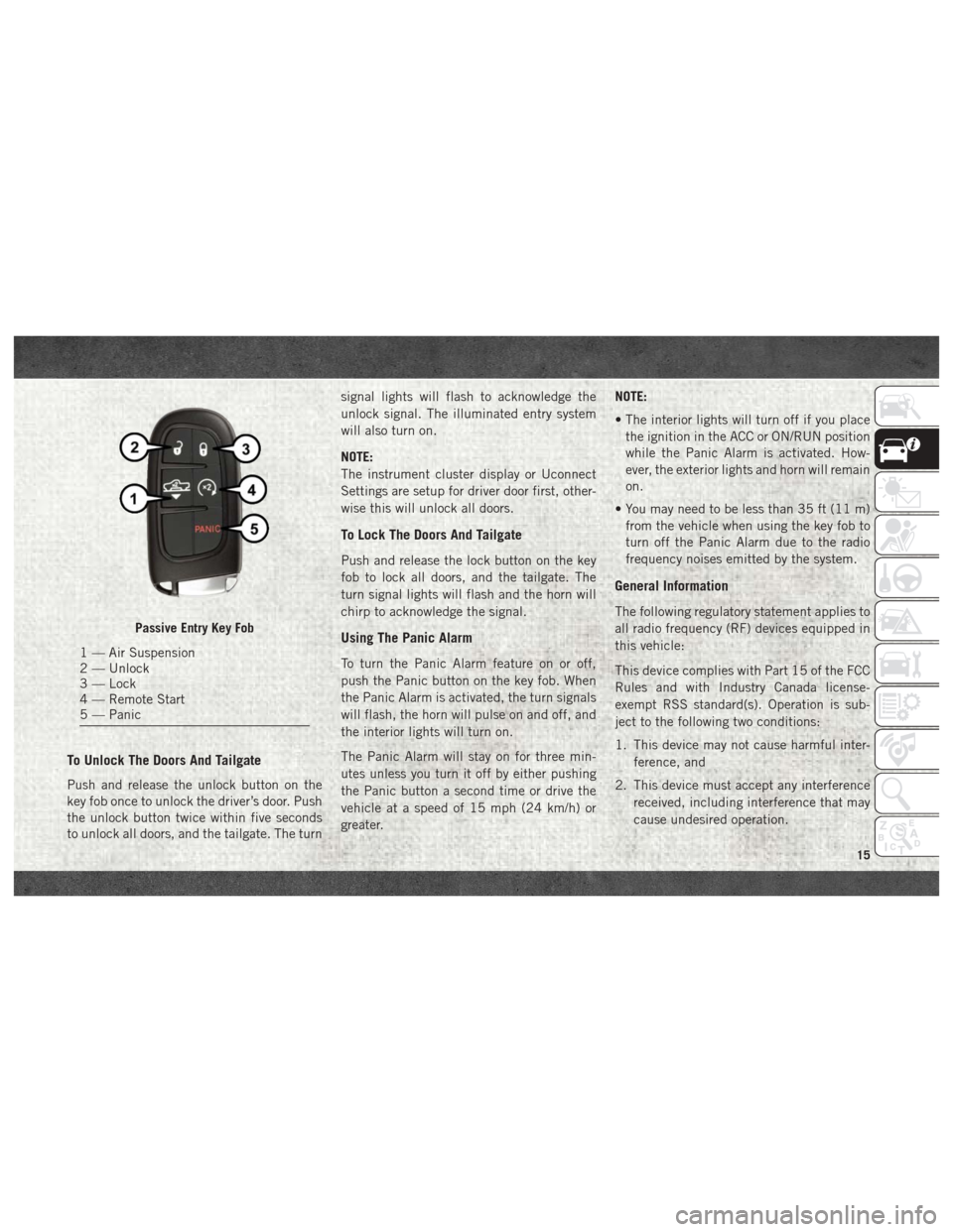
Passive Entry Key Fob
1 — Air Suspension
2 — Unlock
3 — Lock
4 — Remote Start
5 — Panic
15
Page 20 of 298
To Arm The System
Follow these steps to arm the vehicle security
alarm:
1. Remove the key from the ignition system(refer to "Starting The Engine" in "Starting
And Operating" for further information).
• For vehicles equipped with Keyless Enter-N-Go — Ignition, make sure the
vehicle ignition system is "OFF."
• For vehicles not equipped with Keyless Enter-N-Go — Ignition, make sure the
vehicle ignition system is "OFF" and
the key is physically removed from the
ignition.
2. Perform one of the following methods to lock the vehicle:
• Push lock button on the interior power door lock switch with the driver and/or
passenger door open.
• Push the lock button on the exterior Passive Entry Door Handle with a valid
key fob available in the same exterior zone (refer to "Keyless Enter- N-Go —
Passive Entry" in "Getting To Know Your
Vehicle" for further information).
• Push the lock button on the key fob.
3. If any doors are open, close them.
The vehicle security alarm will set when you
use the power door locks, or use the key fob to
lock the doors. After all the doors are locked
and closed, the vehicle security light, in the
instrument panel cluster, will flash rapidly for
about 16 seconds to indicate that the alarm
is being set. After the alarm is set, the vehicle
security light will flash at a slower rate to
indicate that the system is armed.
To Disarm The System
The vehicle security alarm can be disarmed
using any of the following methods:
1. Push the unlock button on the key fob.
2. Grasp the Passive Entry Unlock Door Handle with a valid key fob within 5 ft
(1.5 m) of the passive entry door handle.
If equipped, refer to "Keyless Enter-N-Go
— Passive Entry" in "Getting To Know Your
Vehicle" for further information. 3. Cycle the ignition out of the OFF position.
• For vehicles equipped with KeylessEnter-N-Go — Ignition, push the Key-
less Ignition START/STOP button (re-
quires at least one valid key fob in the
vehicle).
• For vehicles not equipped with Keyless Enter-N-Go, insert a valid key into the
ignition switch and turn the key to the
ON position.
The vehicle security alarm is designed to
protect your vehicle. However, you can create
conditions where the system will give you a
false alarm. If one of the previously described
arming sequences has occurred, the vehicle
security alarm will arm regardless of whether
you are in the vehicle or not. If you remain in
the vehicle and open a door, the alarm will
sound. If this occurs, disarm the vehicle
security alarm.
If the vehicle security alarm is armed and the
battery becomes disconnected, the vehicle
security alarm will remain armed when theGETTING TO KNOW YOUR VEHICLE
18
Page 24 of 298
Programming The Memory Feature
To create a new memory profile, perform the
following:
1. Cycle the vehicle’s ignition to the ON/RUN position (do not start the engine).
2. Adjust all memory profile settings to de- sired preferences (i.e., driver’s seat, out-
side mirrors and radio station presets).
3. Push and release the set (S) button on the memory switch.
4. Within five seconds, push and release either of the memory buttons (1) or (2).
The instrument cluster display will show
which memory position has been set.
NOTE:
• Memory profiles can be set without the vehicle in PARK, but the vehicle must be in
PARK to recall a memory profile.
• To set a memory profile to your key fob, refer to “Linking And Unlinking The Re-
mote Keyless Entry Key Fob To Memory” in
this section.
Linking And Unlinking The Remote Keyless
Entry Key Fob To Memory
Your key fobs can be programmed to recall
one of two pre-programmed memory profiles
by pushing the unlock button on the key fob.
NOTE:
Before programming your key fobs to memory
the feature has to be selected.
• If your vehicle is equipped with a touch-screen, you must select the “Memory To
Fob” feature through the Uconnect system.
Refer to “Uconnect Settings” in “Multimedia”
in the Owner’s Manual at
www.mopar.com/
en-us/care/owners-manual.html (U.S.
Residents) or www.owners.mopar.ca
(Canadian Residents) for further information.
• If your vehicle is not equipped with a touch- screen, you must select the “Key Fob
Linked To Memory” feature through the
instrument cluster display. Refer to “In-
strument Cluster Display” in “Getting To
Know Your Instrument Panel” in the Own-
er’s Manual at www.mopar.com/en-us/
care/owners-manual.html (U.S. Residents)
or www.owners.mopar.ca (Canadian
Residents) for further information. To program your key fobs, perform the follow-
ing:
1. Cycle the vehicle’s ignition to the OFF
position.
2. Select desired memory profile (1) or (2).
NOTE:
If a memory profile has not already been
set, refer to "Programming The Memory
Feature" for instructions on how to set a
memory profile.
3. Once the profile has been recalled, push and release the set (S) button on the
memory switch, then push and release
button (1) or (2) accordingly. “Memory
Profile Set” (1 or 2) will display in the
instrument cluster display.
4. Push and release the lock button on the key fob within 10 seconds.
NOTE:
Your key fobs can be unlinked to your memory
settings by pushing the set (S) button, and
within 10 seconds, followed by pushing the
unlock button on the key fob.GETTING TO KNOW YOUR VEHICLE
22
Page 25 of 298
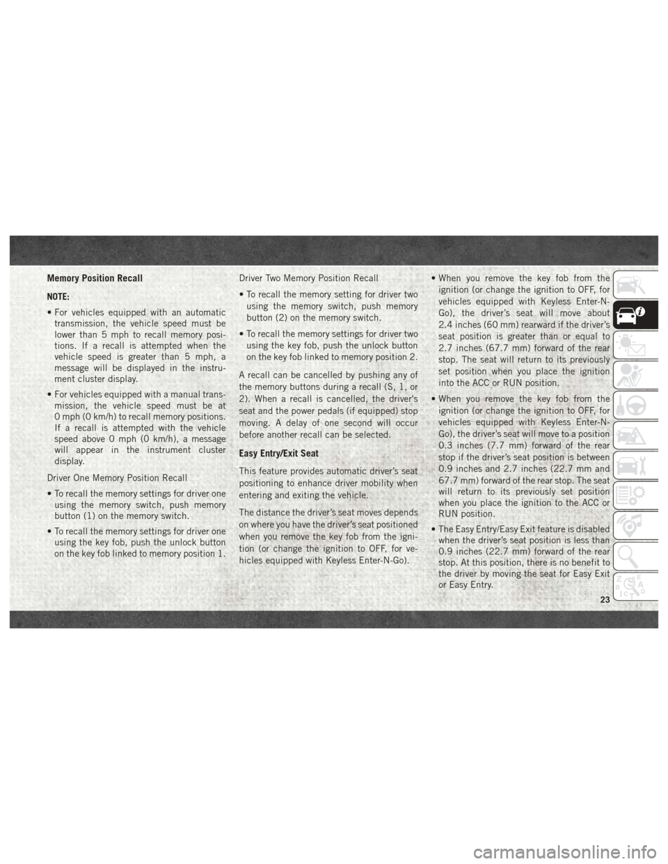
Memory Position Recall
NOTE:
• For vehicles equipped with an automatictransmission, the vehicle speed must be
lower than 5 mph to recall memory posi-
tions. If a recall is attempted when the
vehicle speed is greater than 5 mph, a
message will be displayed in the instru-
ment cluster display.
• For vehicles equipped with a manual trans- mission, the vehicle speed must be at
0 mph (0 km/h) to recall memory positions.
If a recall is attempted with the vehicle
speed above 0 mph (0 km/h), a message
will appear in the instrument cluster
display.
Driver One Memory Position Recall
• To recall the memory settings for driver one using the memory switch, push memory
button (1) on the memory switch.
• To recall the memory settings for driver one using the key fob, push the unlock button
on the key fob linked to memory position 1. Driver Two Memory Position Recall
• To recall the memory setting for driver two
using the memory switch, push memory
button (2) on the memory switch.
• To recall the memory settings for driver two using the key fob, push the unlock button
on the key fob linked to memory position 2.
A recall can be cancelled by pushing any of
the memory buttons during a recall (S, 1, or
2). When a recall is cancelled, the driver's
seat and the power pedals (if equipped) stop
moving. A delay of one second will occur
before another recall can be selected.
Easy Entry/Exit Seat
This feature provides automatic driver’s seat
positioning to enhance driver mobility when
entering and exiting the vehicle.
The distance the driver’s seat moves depends
on where you have the driver’s seat positioned
when you remove the key fob from the igni-
tion (or change the ignition to OFF, for ve-
hicles equipped with Keyless Enter-N-Go). • When you remove the key fob from the
ignition (or change the ignition to OFF, for
vehicles equipped with Keyless Enter-N-
Go), the driver’s seat will move about
2.4 inches (60 mm) rearward if the driver’s
seat position is greater than or equal to
2.7 inches (67.7 mm) forward of the rear
stop. The seat will return to its previously
set position when you place the ignition
into the ACC or RUN position.
• When you remove the key fob from the ignition (or change the ignition to OFF, for
vehicles equipped with Keyless Enter-N-
Go), the driver’s seat will move to a position
0.3 inches (7.7 mm) forward of the rear
stop if the driver’s seat position is between
0.9 inches and 2.7 inches (22.7 mm and
67.7 mm) forward of the rear stop. The seat
will return to its previously set position
when you place the ignition to the ACC or
RUN position.
• The Easy Entry/Easy Exit feature is disabled when the driver’s seat position is less than
0.9 inches (22.7 mm) forward of the rear
stop. At this position, there is no benefit to
the driver by moving the seat for Easy Exit
or Easy Entry.
23
Page 31 of 298
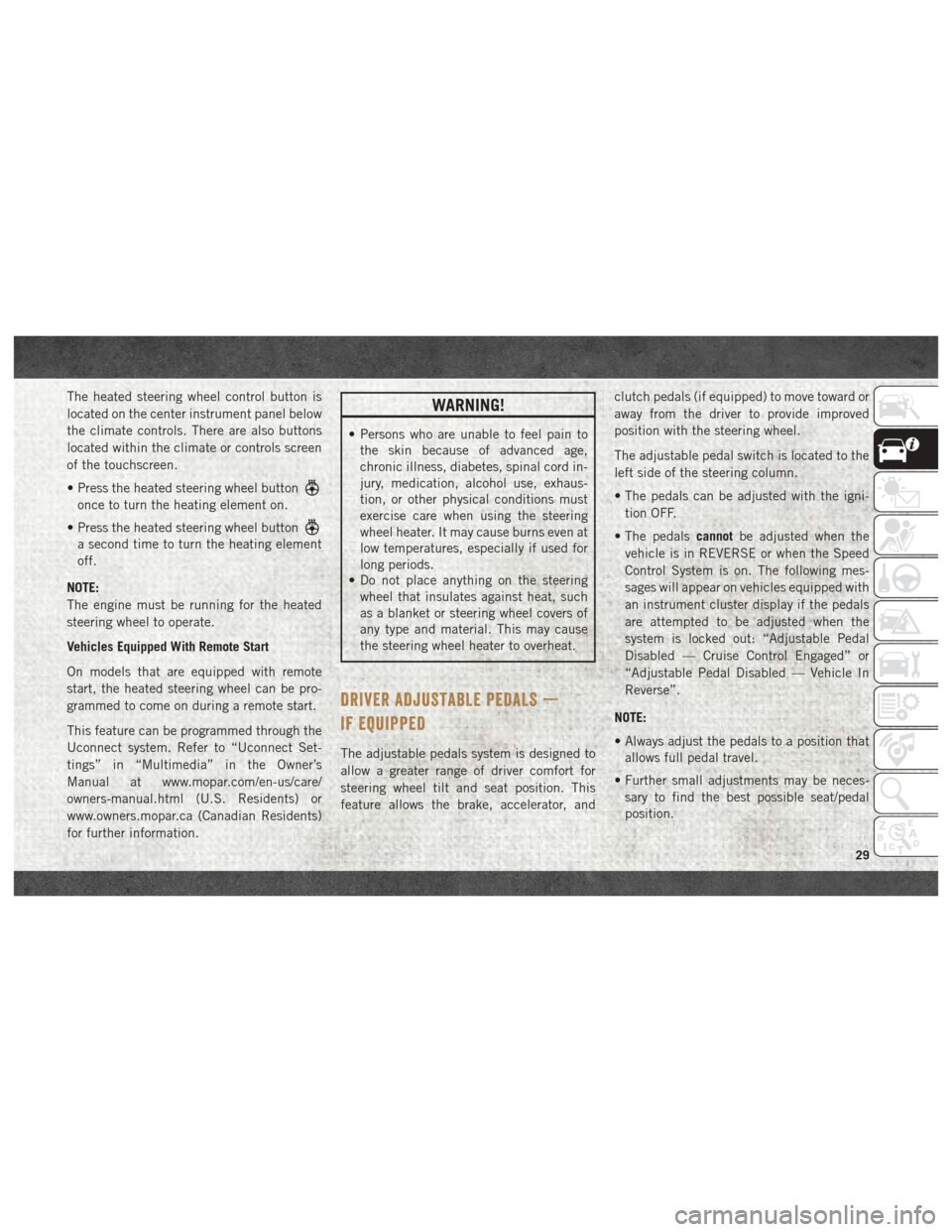
The heated steering wheel control button is
located on the center instrument panel below
the climate controls. There are also buttons
located within the climate or controls screen
of the touchscreen.
• Press the heated steering wheel button
once to turn the heating element on.
• Press the heated steering wheel button
a second time to turn the heating element
off.
NOTE:
The engine must be running for the heated
steering wheel to operate.
Vehicles Equipped With Remote Start
On models that are equipped with remote
start, the heated steering wheel can be pro-
grammed to come on during a remote start.
This feature can be programmed through the
Uconnect system. Refer to “Uconnect Set-
tings” in “Multimedia” in the Owner’s
Manual at www.mopar.com/en-us/care/
owners-manual.html (U.S. Residents) or
www.owners.mopar.ca (Canadian Residents)
for further information.
WARNING!
• Persons who are unable to feel pain to the skin because of advanced age,
chronic illness, diabetes, spinal cord in-
jury, medication, alcohol use, exhaus-
tion, or other physical conditions must
exercise care when using the steering
wheel heater. It may cause burns even at
low temperatures, especially if used for
long periods.
• Do not place anything on the steering
wheel that insulates against heat, such
as a blanket or steering wheel covers of
any type and material. This may cause
the steering wheel heater to overheat.
DRIVER ADJUSTABLE PEDALS —
IF EQUIPPED
The adjustable pedals system is designed to
allow a greater range of driver comfort for
steering wheel tilt and seat position. This
feature allows the brake, accelerator, and clutch pedals (if equipped) to move toward or
away from the driver to provide improved
position with the steering wheel.
The adjustable pedal switch is located to the
left side of the steering column.
• The pedals can be adjusted with the igni-
tion OFF.
• The pedals cannotbe adjusted when the
vehicle is in REVERSE or when the Speed
Control System is on. The following mes-
sages will appear on vehicles equipped with
an instrument cluster display if the pedals
are attempted to be adjusted when the
system is locked out: “Adjustable Pedal
Disabled — Cruise Control Engaged” or
“Adjustable Pedal Disabled — Vehicle In
Reverse”.
NOTE:
• Always adjust the pedals to a position that allows full pedal travel.
• Further small adjustments may be neces- sary to find the best possible seat/pedal
position.
29
Page 34 of 298
breakage than glass lights. Plastic is not as
scratch resistant as glass and therefore dif-
ferent lens cleaning procedures must be fol-
lowed.
To minimize the possibility of scratching the
lenses and reducing light output, avoid wip-
ing with a dry cloth. To remove road dirt, wash
with a mild soap solution followed by rinsing.
NOTE:
If your vehicle is equipped with illuminated
approach lights under the outside mirrors,
they can be turned off through the instrument
cluster or the Uconnect radio. For further
information, refer to the Owner’s Manual at
www.mopar.com/en-us/care/owners-manual.html
(U.S. Residents) or www.owners.mopar.ca
(Canadian Residents) for further information.
CAUTION!
Do not use abrasive cleaning components,
solvents, steel wool or other abrasive ma-
terials to clean the lenses.
Headlights
To turn on the headlights, rotate the head-
light switch clockwise to the headlight posi-
tion. When the headlight switch is on, the
parking lights, taillights, license plate light
and instrument panel lights are also turned
on. To turn off the headlights, rotate the
headlight switch back to the O (off) position.
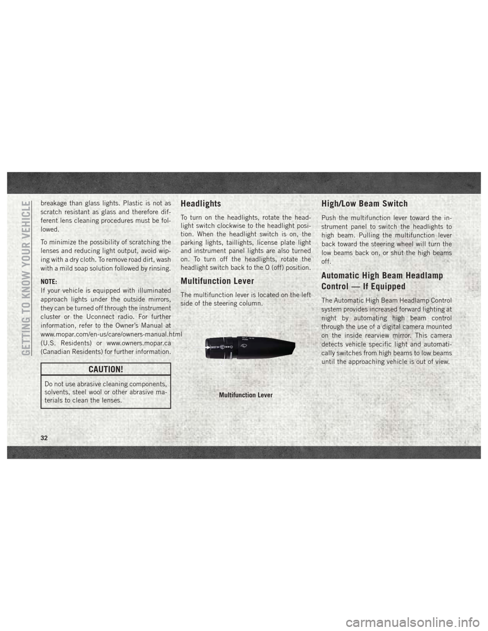
Multifunction Lever
The multifunction lever is located on the left
side of the steering column.
High/Low Beam Switch
Push the multifunction lever toward the in-
strument panel to switch the headlights to
high beam. Pulling the multifunction lever
back toward the steering wheel will turn the
low beams back on, or shut the high beams
off.
Automatic High Beam Headlamp
Control — If Equipped
The Automatic High Beam Headlamp Control
system provides increased forward lighting at
night by automating high beam control
through the use of a digital camera mounted
on the inside rearview mirror. This camera
detects vehicle specific light and automati-
cally switches from high beams to low beams
until the approaching vehicle is out of view.
Multifunction Lever
GETTING TO KNOW YOUR VEHICLE
32
Page 36 of 298
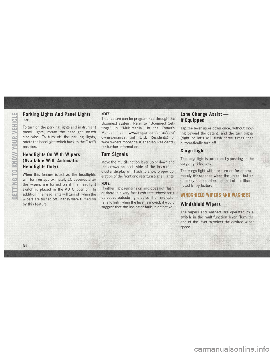
Parking Lights And Panel Lights
To turn on the parking lights and instrument
panel lights, rotate the headlight switch
clockwise. To turn off the parking lights,
rotate the headlight switch back to the O (off)
position.
Headlights On With Wipers
(Available With Automatic
Headlights Only)
When this feature is active, the headlights
will turn on approximately 10 seconds after
the wipers are turned on if the headlight
switch is placed in the AUTO position. In
addition, the headlights will turn off when the
wipers are turned off, if they were turned on
by this feature.NOTE:
This feature can be programmed through the
Uconnect system. Refer to “Uconnect Set-
tings” in “Multimedia” in the Owner’s
Manual at www.mopar.com/en-us/care/
owners-manual.html (U.S. Residents) or
www.owners.mopar.ca (Canadian Residents)
for further information.
Turn Signals
Move the multifunction lever up or down and
the arrows on each side of the instrument
cluster display will flash to show proper op-
eration of the front and rear turn signal lights.
NOTE:
If either light remains on and does not flash,
or there is a very fast flash rate, check for a
defective outside light bulb. If an indicator
fails to light when the lever is moved, it would
suggest that the indicator bulb is defective.
Lane Change Assist —
If Equipped
Tap the lever up or down once, without mov-
ing beyond the detent, and the turn signal
(right or left) will flash three times then
automatically turn off.
Cargo Light
The cargo light is turned on by pushing on the
cargo light button.
The cargo light will also turn on for approxi-
mately 60 seconds when the unlock button
on a key fob is pushed, as part of the Illumi-
nated Entry feature.
WINDSHIELD WIPERS AND WASHERS
Windshield Wipers
The wipers and washers are operated by a
switch in the multifunction lever. Turn the
end of the lever to select the desired wiper
speed.
GETTING TO KNOW YOUR VEHICLE
34
Page 48 of 298
• The HomeLink buttons that are located inthe overhead console or sunvisor designate
the three different HomeLink channels.
• To operate HomeLink, push and release any of the programmed HomeLink buttons.
These buttons will activate the devices they
are programmed to with each press of the
corresponding HomeLink button.
Before You Begin Programming
HomeLink
For efficient programming and accurate
transmission of the radio-frequency signal, it
is recommended that a new battery be placed
in the hand-held transmitter of the device
that is being programmed to the HomeLink
system. Make sure your hand-held transmit-
ter is programmed to activate the device you
are trying to program your HomeLink button
to.
Ensure that your vehicle is parked outside of
the garage before you begin programming.
It is recommended that you erase all the
channels of your HomeLink before you use it
for the first time. If you have any problems, or require assis-
tance, please call toll-free 1-800-355-3515
or, on the Internet at HomeLink.com for in-
formation or assistance.
Erasing All The HomeLink
Channels
To erase the channels, follow this procedure:
1. Place the ignition switch into the ON/RUN
position.
NOTE:
For vehicle’s equipped with Keyless
Enter-N-Go, place the ignition in the RUN
position with the Engine ON. Make sure to
program HomeLink with the vehicle out-
side of the garage, or with the garage door
open at all times.
2. Push and hold the two outside HomeLink buttons (I and III) for up to 20 seconds, or
until the instrument cluster display
switches from the “Clearing Channels”
message to the “Channels Cleared”
message. NOTE:
Erasing all channels should only be per-
formed when programming HomeLink for the
first time. Do not erase channels when pro-
gramming additional buttons.
Identifying Whether You Have A
Rolling Code Or Non-Rolling Code
Device
Before programming a device to one of your
HomeLink buttons, you must determine
whether the device has a rolling code or
non-rolling code.
Rolling Code Devices
To determine if your device has a rolling code,
a good indicator is its manufacturing date.
Typically, devices manufactured after
1995 have rolling codes. A device with a
rolling code will also have a “LEARN” or
“TRAIN” button located where the antenna is
attached to the device. The button may not
be immediately visible when looking at the
device. The name and color of the button may
vary slightly by manufacturer.
GETTING TO KNOW YOUR VEHICLE
46
Page 49 of 298
NOTE:
The “LEARN” or “TRAIN” button is not the
button you normally use to operate the de-
vice.
Non-rolling Code Devices
Most devices manufactured before 1995 will
not have a rolling code. These devices will
also not have a “LEARN” or “TRAIN” button.
Programming HomeLink To A
Garage Door Opener
To program any of the HomeLink buttons to
activate your garage door opener motor, fol-
low the steps below:
NOTE:
All HomeLink buttons are programmed using
this procedure. You do not need to erase all
channels when programming additional but-
tons.
1. Place the ignition switch into the ON/RUNposition. NOTE:
For vehicle’s equipped with Keyless Enter-
N-Go, place the ignition in the RUN posi-
tion with the Engine ON. Make sure to
program HomeLink with the vehicle out-
side of the garage, or with the garage door
open at all times.
2. Place the garage door opener transmitter 1 to 3 inches (3 to 8 cm) away from the
HomeLink button you wish to program,
while keeping the HomeLink indicator
light in view.
3. Push and hold the HomeLink button you want to program while you push and hold
the garage door opener transmitter button
you are trying to replicate .
4. Continue to hold both buttons until the Instrument Cluster Display changes from
“CHANNEL # TRAINING” to “CHANNEL
# TRAINED.” Once this happens, release
both buttons. NOTE:
• It may take up to 30 seconds or longer in some cases for the channel to train.
• If “DID NOT TRAIN” appears in the instrument cluster display repeat from
Step 2.
NOTE:
Make sure the garage door opener motor is
plugged in before moving on to the rolling
code/non-rolling code final steps.
Rolling Code Garage Door Opener Final Steps
NOTE:
You have 30 seconds in which to initiate
rolling code final step 2, after completing
rolling code final step 1.
1. At the garage door opener motor (in the garage), locate the “LEARN” or “TRAIN”
button. This can usually be found where
the hanging antenna wire is attached to
the garage door opener motor. Firmly push
and release the “LEARN” or “TRAIN”
button.
47