fuses RAM CHASSIS CAB 2021 Owners Manual
[x] Cancel search | Manufacturer: RAM, Model Year: 2021, Model line: CHASSIS CAB, Model: RAM CHASSIS CAB 2021Pages: 463, PDF Size: 21.5 MB
Page 346 of 463

344IN CASE OF EMERGENCY
Replace the wheel covers using a rubber mallet
to ease the installation. Align the wheel cover
vent holes to the wheel vent holes. Tap on the
wheel cover as needed to firmly seat it evenly
around the wheel.
JUMP STARTING
If your vehicle has a discharged battery, it can
be jump started using a set of jumper cables
and a battery in another vehicle, or by using a
portable battery booster pack. Jump starting
can be dangerous if done improperly, so please
follow the procedures in this section carefully. NOTE:
When using a portable battery booster pack,
follow the manufacturer's operating instruc
-
tions and precautions.
PREPARATIONS FOR JUMP START
The battery in your vehicle is located in the front
of the engine compartment, behind the left
headlight assembly.
Battery Location
If you have a diesel engine, you may have two
batteries, however jump start off the driver side
battery.
The positive battery post may be covered with a
protective cap if equipped. Lift up on the cap to
gain access to the positive battery post. Do not
jump off fuses. Only jump directly off positive
post which has a positive
(+) symbol on or
around the post.
Positive (+) Battery Post
NOTE:
1. Apply the parking brake, shift the automatic transmission into PARK and
turn the ignition OFF.
2. Turn off the heater, radio, and all electrical accessories.
The rear hub caps on the dual rear wheel
has two pull off notches. Make sure that the
hook of the jack handle driver is located
squarely in the cap notch before attempting
to pull off.
WARNING!
Do not attempt jump starting if the battery is
frozen. It could rupture or explode and cause
personal injury.
CAUTION! (Continued)CAUTION!
Do not use a portable battery booster pack or
any other booster source with a system
voltage greater than 12 Volts or damage to
the battery, starter motor, alternator or
electrical system may occur.
21_DPF_OM_EN_USC_t.book Page 344
Page 347 of 463

IN CASE OF EMERGENCY345
3. If using another vehicle to jump start the
battery, park the vehicle within the jumper
cables reach, apply the parking brake, and
make sure the ignition is OFF.JUMP STARTING PROCEDURE
NOTE:
Make sure at all times that unused ends of
jumper cables are not contacting each other or
either vehicle while making connections.
Connecting The Jumper Cables
1. Connect the positive
(+) end of the jumper
cable to the positive (+)
post of the
discharged vehicle.
NOTE:
Do not jump off fuses. Only jump directly off
positive post. 2. Connect the opposite end of the positive
(+)
jumper cable to the positive (+) post of the
booster battery.
3. Connect the negative (-) end of the jumper
cable to the negative (-) post of the booster
battery.
4. Connect the opposite end of the negative (-)
jumper cable to a good engine ground.
A “ground” is an exposed metallic/
unpainted part of the engine, frame or
chassis, such as an accessory bracket or
large bolt. The ground must be away from
the battery and fuel injection system.
5. Start the engine in the vehicle that has the booster battery, let the engine idle a few
minutes, and then start the engine in the
vehicle with the discharged battery.
WARNING!
Take care to avoid the radiator cooling fan
whenever the hood is raised. It can start
anytime the ignition switch is ON. You can
be injured by moving fan blades.
Remove any metal jewelry such as rings,
watch bands and bracelets that could
make an inadvertent electrical contact.
You could be seriously injured.
Batteries contain sulfuric acid that can
burn your skin or eyes and generate
hydrogen gas which is flammable and
explosive. Keep open flames or sparks
away from the battery.
WARNING!
Do not allow vehicles to touch each other as
this could establish a ground connection and
personal injury could result.
WARNING!
Failure to follow this jump starting procedure
could result in personal injury or property
damage due to battery explosion.
CAUTION!
Failure to follow these procedures could
result in damage to the charging system of
the booster vehicle or the discharged vehicle.
WARNING!
Do not connect the jumper cable to the
negative (-) post of the discharged battery.
The resulting electrical spark could cause the
battery to explode and could result in
personal injury.7
21_DPF_OM_EN_USC_t.book Page 345
Page 348 of 463

346IN CASE OF EMERGENCY
6. Once the engine is started, follow the
disconnecting procedure below.
Disconnecting The Jumper Cables
1. Disconnect the negative
(-)
end of the
jumper cable from the engine ground of
the vehicle with the discharged battery.
2. Disconnect the opposite end of the negative (-) jumper cable from the
negative (-) post of the booster battery.
3. Disconnect the positive (+) end of the
jumper cable from the positive (+) post of
the booster battery.
4. Disconnect the opposite end of the positive (+) jumper cable from the
positive (+) post of the vehicle with the
discharged battery.
If frequent jump starting is required to start your
vehicle you should have the battery and charging
system inspected at an authorized dealer.
IF YOUR ENGINE OVERHEATS
In any of the following situations, you can
reduce the potential for overheating by taking
the appropriate action.
On the highways — slow down.
In city traffic — while stopped, place the trans
-
mission in NEUTRAL, but do not increase the
engine idle speed while preventing vehicle
motion with the brakes. NOTE:
There are steps that you can take to slow down
an impending overheat condition:
If your Air Conditioner (A/C) is on, turn it off.
The A/C system adds heat to the engine
cooling system and turning the A/C off can
help remove this heat.
You can also turn the temperature control to
maximum heat, the mode control to floor and
the blower control to high. This allows the
heater core to act as a supplement to the
radiator and aids in removing heat from the
engine cooling system.
CAUTION!
Do not connect jumper cable to any of the
fuses on the positive battery terminal. The
resulting electrical current will blow the fuse.
CAUTION!
Accessories plugged into the vehicle power
outlets draw power from the vehicle’s battery,
even when not in use (i.e., cellular devices,
etc.). Eventually, if plugged in long enough
without engine operation, the vehicle’s battery
will discharge sufficiently to degrade battery
life and/or prevent the engine from starting.
WARNING!
You or others can be badly burned by hot
engine coolant (antifreeze) or steam from
your radiator. If you see or hear steam coming
from under the hood, do not open the hood
until the radiator has had time to cool. Never
try to open a cooling system pressure cap
when the radiator or coolant bottle is hot.
21_DPF_OM_EN_USC_t.book Page 346
Page 366 of 463

364SERVICING AND MAINTENANCE
ENGINE COMPARTMENT
6.4L ENGINE
1 — Engine Coolant Pressure Cap 6 — Battery
2 — Engine Coolant Pressure Reservoir 7 — Engine Air Cleaner Filter
3 — Engine Oil Fill 8 — Power Steering Reservoir Cap
4 — Engine Oil Dipstick 9 — Power Distribution Center (Fuses)
5 — Brake Fluid Reservoir Cap 10 — Washer Fluid Reservoir Cap
21_DPF_OM_EN_USC_t.book Page 364
Page 367 of 463

SERVICING AND MAINTENANCE365
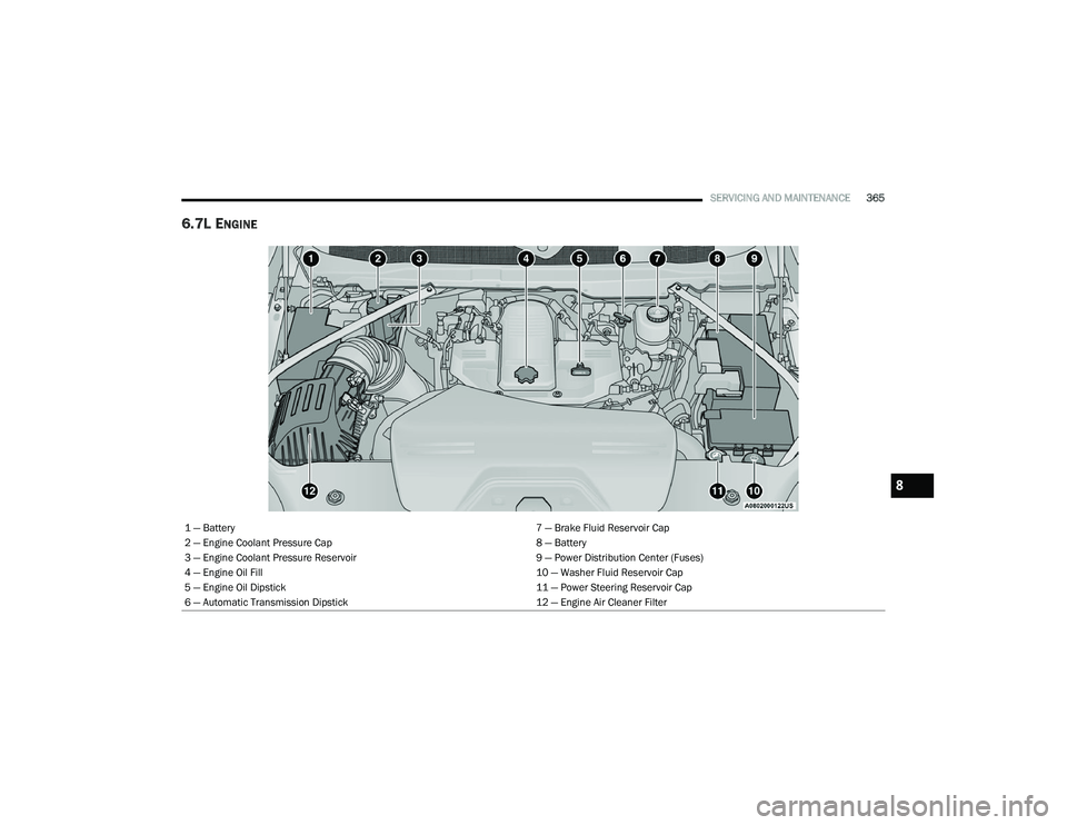
6.7L ENGINE
1 — Battery 7 — Brake Fluid Reservoir Cap
2 — Engine Coolant Pressure Cap 8 — Battery
3 — Engine Coolant Pressure Reservoir 9 — Power Distribution Center (Fuses)
4 — Engine Oil Fill 10 — Washer Fluid Reservoir Cap
5 — Engine Oil Dipstick 11 — Power Steering Reservoir Cap
6 — Automatic Transmission Dipstick 12 — Engine Air Cleaner Filter
8
21_DPF_OM_EN_USC_t.book Page 365
Page 396 of 463

394SERVICING AND MAINTENANCE
(Continued)
FUSES
General Information The fuses protect electrical systems against
excessive current.
When a device does not work, you must check
the fuse element inside the blade fuse for a
break/melt.
Also, please be aware that when using power
outlets for extended periods of time with the
engine off may result in vehicle battery
discharge.
Blade Fuses
PERFORMED BY
PERFORMED AT
Noise Systems Maintenance Chart and Service Log — Insert Month, Day, Year under column mileage closest to the mileage at which
service was performed.
WARNING!
When replacing a blown fuse, always use
an appropriate replacement fuse with the
same amp rating as the original fuse. Never
replace a fuse with another fuse of higher
amp rating. Never replace a blown fuse with
metal wires or any other material. Do not
place a fuse inside a circuit breaker cavity
or vice versa. Failure to use proper fuses
may result in serious personal injury, fire
and/or property damage.
Before replacing a fuse, make sure that the
ignition is off and that all the other services
are switched off and/or disengaged.
If the replaced fuse blows again, contact an
authorized dealer.
If a general protection fuse for safety
systems (air bag system, braking system),
power unit systems (engine system, trans
-
mission system) or steering system blows,
contact an authorized dealer.
WARNING! (Continued)
1 — Fuse Element
2 — Blade Fuse with a good/functional fuse
element
3 — Blade fuse with a bad/not functional fuse
element (blown fuse)
21_DPF_OM_EN_USC_t.book Page 394
Page 397 of 463

SERVICING AND MAINTENANCE395
Power Distribution Center
The Power Distribution Center is located in the
engine compartment near the battery. This
center contains cartridge fuses, micro fuses,
relays, and circuit breakers. A description of
each fuse and component may be stamped on
the inside cover, otherwise the cavity number of
each fuse is stamped on the inside cover that
corresponds to the following chart.
Power Distribution Center Location
Cavity Cartridge FuseMicro Fuse Description
F01– –Spare
F02 60 Amp Yellow –ABS Pump Motor (HD Only)
F03 60 Amp Yellow –Rad Fan – If Equipped
F04 50 Amp Red 400W Inverter – If Equipped
F05 40 Amp Green –Compressor For Air Suspension – If Equipped
F06 40 Amp Green –Steering Torque Overlay Module (STOM)
F07 40 Amp Green –Starter Solenoid
F08 20 Amp Blue –NOX Sensor – If Equipped
F09 40 Amp Green –Diesel / Fuel Heater – If Equipped
F09 30 Amp Pink –Gas / Brake Vacuum Pump – If Equipped
F10 40 Amp Green –CBC #2 / Ext Lights
F11 40 Amp Green –Brake System Module (ECU and Valves)
8
21_DPF_OM_EN_USC_t.book Page 395
Page 455 of 463

453
Fluid Level Checks Brake
........................................................ 387Power Steering.......................................... 163Fog Lights............................................... 53, 404Fold Flat Load Floor......................................... 70Fold-Flat Seats................................................. 33Forward Collision Warning............................. 281Four Wheel Drive........................................... 153Four-Way Hazard Flasher............................... 334Freeing A Stuck Vehicle................................. 349Front Axle (Differential).................................. 390Fuel............................................ 196, 433, 436Adding....................................................... 195Additives................................................... 434Clean Air.................................................... 433Diesel.............................................. 196, 436Ethanol...................................................... 434Filler Cap (Gas Cap)................................... 196Filter................................................ 375, 440Gasoline.................................................... 433Light.......................................................... 111Materials Added........................................ 434Methanol................................................... 434Octane Rating........................................... 433Requirements................................. 433, 436Specifications............................................ 436Tank Capacity............................................ 439Fuses............................................................. 394
G
Garage Door Opener (HomeLink)..................... 47Gas Cap (Fuel Filler Cap).............................. 196Gasoline, Clean Air........................................ 433Gasoline, Reformulated................................ 433GaugesVoltage..................................................... 128Gear Ranges................................................. 147Gear Selector Override................................. 347Glass Cleaning.............................................. 430Gross Axle Weight Rating.............................. 201Gross Vehicle Weight Rating......................... 201GuideBody Builders.............................................. 10GVWR............................................................ 199
H
HazardDriving Through Flowing, Rising, Or Shallow Standing Water
.................................... 218Hazard Warning Flashers.............................. 334Head Restraints............................................... 38Head Rests...................................................... 38Headlights.................................................... 402Automatic High Beam.................................. 52Cleaning................................................... 427High Beam................................................... 51Lights On Reminder..................................... 53Passing........................................................ 52Switch.......................................................... 50
Heated Mirrors.................................................46Heated Seats...................................................37Hill Descent Control...................................... 278Hill Descent Control Indicator....................... 278Hill Start Assist.............................................. 280HitchesTrailer Towing........................................... 204HomeLink (Garage Door Opener).....................47Hood Prop........................................................79Hood Release...................................................79Hub Caps...................................................... 343
I
Idle-Up Feature............................................. 132Ignition.............................................................18Switch..........................................................18Illuminated Entry..............................................56Inside Rearview Mirror.................... 41, 42, 335Instrument Cluster...................... 85, 86, 88, 89Descriptions.............................................. 115Display.........................................................90Engine Oil Reset..........................................91Instrument Panel Lens Cleaning................... 429Integrated Trailer Brake Control.................... 207Interior Appearance Care.............................. 428Interior Lights...................................................55Intermittent Wipers (Delay Wipers)..................57Intervention Regeneration Strategy..... 101, 379Inverter Outlet (115V)......................................74
11
21_DPF_OM_EN_USC_t.book Page 453
Page 457 of 463

455
Manual Park Release
............................................. 348Service...................................................... 448Media Hub....................................................... 72Media Mode.................................................. 255Memory Seat................................................... 32Memory Settings............................................. 32Methanol....................................................... 434Mirrors............................................................. 41Electric Powered......................................... 44Heated........................................................ 46Memory....................................................... 32Outside........................................................ 44Rearview..................................... 41, 42, 335Trailer Towing.............................................. 46Modifications/AlterationsVehicle........................................................ 10Monitor, Tire Pressure System....................... 284Mopar Parts................................................... 447MP3 Control.................................................... 72Multi-Function Control Lever............................ 51
N
Navigation System (Uconnect GPS)............... 186New Vehicle Break-In Period................ 136, 137Noise ControlMaintenance............................................. 391Tampering Prohibited................................ 392Noise Emission Warranty..................... 391, 392
O
Occupant Restraints..................................... 292Octane Rating, Gasoline (Fuel)..................... 433Oil Change Indicator..................................... 357Oil Filter, Change.......................................... 369Oil Filter, Selection........................................ 369Oil Pressure Light.......................................... 108Oil Reset.......................................................... 91Oil, Engine............................................ 368, 440Capacity.................................................... 439Dipstick.................................................... 366Disposal................................................... 369Filter................................................ 369, 440Filter Disposal........................................... 369Identification Logo.................................... 368Materials Added To.................................. 368Pressure Warning Light............................ 108Recommendation..................................... 368Synthetic.................................................. 368Onboard Diagnostic System.......................... 116Operating Precautions.................................. 116Operator ManualOwner's Manual........................................ 448Outside Rearview Mirrors................................ 44Overdrive...................................................... 151Overdrive OFF Switch.................................... 151Overheating, Engine...................................... 346
P
Paint Care..................................................... 427Pair (Link) Uconnect Phone To A Mobile
Phone .................................................... 260Parking Brake............................................... 137ParkSense System, Rear............................... 177Passive Entry....................................................26Pedals, Adjustable...........................................40Pets............................................................... 330Phone Mode.................................................. 258Placard, Tire And Loading Information.......... 411Power
Distribution Center (Fuses)....................... 395Door Locks...................................................25Mirrors.........................................................44Outlet (Auxiliary Electrical Outlet)..........73, 74Seats...........................................................35Sliding Rear Window....................................78Steering............................................. 44, 163Take-Off Adapter....................................... 163Take-Off Operation.................................... 163Windows......................................................76Power SeatsDown...........................................................35Forward.......................................................35Rearward.....................................................35Recline.........................................................35Tilt................................................................35Up................................................................35
11
21_DPF_OM_EN_USC_t.book Page 455