tow RAM CHASSIS CAB 2021 Owners Manual
[x] Cancel search | Manufacturer: RAM, Model Year: 2021, Model line: CHASSIS CAB, Model: RAM CHASSIS CAB 2021Pages: 463, PDF Size: 21.5 MB
Page 4 of 463
2
INTRODUCTION
Symbols Key ..........................................................10
VAN CONVERSIONS/CAMPERS ..........................10
VEHICLE MODIFICATIONS/ALTERATIONS .........10
Symbol Glossary ...................................................11
GETTING TO KNOW YOUR VEHICLE
KEYS ......................................................................15
Key Fob......................................................... 15
SENTRY KEY ..........................................................17
IGNITION SWITCH .................................................18
Keyless Push Button Ignition ...................... 18
REMOTE START — IF EQUIPPED (GASOLINE) ..20
How To Use Remote Start ........................... 20
To Exit Remote Start Mode ......................... 21
Remote Start Front Defrost
Activation — If Equipped .............................. 21 Remote Start Comfort Systems —
If Equipped ................................................... 21 Remote Start Abort Message ...................... 22
REMOTE START — IF EQUIPPED (DIESEL) .........22
How To Use Remote Start ........................... 23
VEHICLE SECURITY SYSTEM — IF EQUIPPED ...23
To Arm The System ...................................... 23
To Disarm The System................................. 24
Rearming Of The System............................. 24
Security System Manual Override .............. 24 DOORS .................................................................. 24
Manual Door Locks...................................... 24
Power Door Locks — If Equipped ............... 25
Keyless Enter-N-Go — Passive Entry
(If Equipped) ................................................ 26 Automatic Unlock Doors On
Exit — If Equipped ........................................ 28 Automatic Door Locks — If Equipped ......... 28
Child-Protection Door Lock — If Equipped.. 28
STEERING WHEEL ............................................... 29
Tilt Steering Column .................................... 29
Heated Steering Wheel — If Equipped ....... 29
UCONNECT VOICE RECOGNITION ....................... 30
Introducing Voice Recognition .................... 30
Basic Voice Commands............................... 31
Get Started ................................................... 31
Additional Information ................................. 31
DRIVER MEMORY SETTINGS — IF EQUIPPED ... 32
Programming The Memory Feature............ 32
Linking And Unlinking The Remote
Keyless Entry Key Fob To Memory ............. 32 Memory Position Recall............................... 33
SEATS .................................................................... 33
Manual Front Seat Adjustment................... 34
Power Driver Seat Adjustment —
If Equipped ................................................... 35 Heated Seats — If Equipped ....................... 36
Ventilated Seats — If Equipped................... 37
Head Restraints ........................................... 38 DRIVER ADJUSTABLE PEDALS —
IF EQUIPPED .........................................................40
MIRRORS ..............................................................41
Inside Rearview Mirror ................................ 41
Illuminated Vanity Mirror — If Equipped ..... 43
Outside Mirrors ........................................... 44
Driver's Outside Automatic Dimming
Mirror — If Equipped .................................... 44 Power Mirrors — If Equipped ...................... 44
Power Convex Mirror Switch —
If Equipped ................................................... 45 Trailer Towing Mirrors.................................. 46
Heated Mirrors — If Equipped ..................... 46
Tilt Side Mirrors In Reverse — If Equipped ... 46
Outside Mirrors Folding Feature ................. 46
UNIVERSAL GARAGE DOOR OPENER
(HOMELINK®) — IF EQUIPPED ...........................47
Before You Begin Programming
HomeLink® .................................................. 47 Erasing All The HomeLink® Channels ....... 47
Identifying Whether You Have A Rolling
Code Or Non-Rolling Code Device .............. 47 Programming HomeLink® To A Garage
Door Opener................................................. 48 Programming HomeLink® To A
Miscellaneous Device ................................. 49 Reprogramming A Single HomeLink®
Button ........................................................... 49 Canadian/Gate Operator Programming..... 50
21_DPF_OM_EN_USC_t.book Page 2
Page 7 of 463
5
LANESENSE — IF EQUIPPED ........................... 183 LaneSense Operation ................................183Turning LaneSense On Or Off ...................184LaneSense Warning Message ..................184
Changing LaneSense Status .....................186
PARKVIEW REAR BACK UP CAMERA ............ 186
AUX Camera — If Equipped .......................188
SURROUND VIEW CAMERA SYSTEM — IF
EQUIPPED ........................................................... 189
AUX Camera — If Equipped .......................194
ENGINE RUNAWAY ............................................ 195
REFUELING THE VEHICLE — GASOLINE
ENGINE ................................................................ 195
Loose Fuel Filler Cap Message ................196
REFUELING THE VEHICLE — DIESEL
ENGINE ............................................................... 196
Diesel Exhaust Fluid ..................................196
VEHICLE LOADING ............................................ 199
Gross Vehicle Weight Rating (GVWR) ......199Payload .......................................................199Gross Axle Weight Rating (GAWR) ............200
Tire Size ......................................................200
Rim Size......................................................200
Inflation Pressure ......................................200
Curb Weight................................................200
Loading .......................................................200 TRAILER TOWING ............................................... 200
Common Towing Definitions ..................... 201Trailer Hitch Type and Maximum Trailer
Weight ........................................................ 204 Trailer Towing Weights (Maximum Trailer
Weight Ratings) ......................................... 205 Trailer And Tongue Weight ....................... 205
Towing Requirements ............................... 205Towing Tips ................................................ 211
SNOWPLOW — IF EQUIPPED ............................ 212
Before Plowing ........................................... 212
Snowplow Prep Package Model
Availability .................................................. 212 Over The Road Operation With Snowplow
Attached ..................................................... 213 Operating Tips ............................................ 213General Maintenance................................ 213
RECREATIONAL TOWING (BEHIND
MOTORHOME) ...................................................214
Towing This Vehicle Behind Another
Vehicle ........................................................ 214 Recreational Towing — Two-Wheel Drive
Models ........................................................ 215 Recreational Towing — Four-Wheel Drive
Models ........................................................ 215
DRIVING TIPS ...................................................... 218
Driving On Slippery Surfaces ................... 218
Driving Through Water .............................. 218
MULTIMEDIA
UCONNECT SYSTEMS ....................................... 220
CYBERSECURITY ............................................... 220
UCONNECT 3.0 ................................................... 221 Introduction................................................ 221
Radio Mode ................................................ 222
Media Mode ............................................... 224
Phone Mode............................................... 225
UCONNECT SETTINGS ....................................... 228
Customer Programmable Features .......... 228
UCONNECT INTRODUCTION.............................. 244
System Overview ...................................... 244
Safety And General Information ............... 246
UCONNECT MODES ........................................... 247
Steering Wheel Audio Controls ................. 247
Radio Mode ............................................... 247
Media Mode .............................................. 255Phone Mode .............................................. 258
RADIO OPERATION AND MOBILE PHONES.... 269
Regulatory And Safety Information .......... 269
OFF-ROAD PAGES — IF EQUIPPED .................. 270
Off-Road Pages Status Bar ....................... 270Vehicle Dynamics ...................................... 271
Accessory Gauge ....................................... 271
Pitch & Roll................................................. 272Forward Facing Camera ............................ 272
21_DPF_OM_EN_USC_t.book Page 5
Page 8 of 463
6
SAFETY
SAFETY FEATURES ............................................ 273
Anti-Lock Brake System (ABS) ................. 273
Electronic Brake Control (EBC) System ...274
AUXILIARY DRIVING SYSTEMS ........................ 281
Forward Collision Warning (FCW) With
Mitigation — If Equipped............................281 Tire Pressure Monitoring
System (TPMS) ..........................................284
OCCUPANT RESTRAINT SYSTEMS .................. 292
Occupant Restraint Systems Features ....292
Important Safety Precautions ...................293Seat Belt Systems ..................................... 293Supplemental Restraint Systems (SRS) ...302Child Restraints..........................................312
SAFETY TIPS ...................................................... 330
Transporting Passengers ..........................330
Transporting Pets ......................................330
Safety Checks You Should Make Inside
The Vehicle ................................................330 Periodic Safety Checks You Should Make
Outside The Vehicle ...................................332 Exhaust Gas ...............................................333Carbon Monoxide Warnings ......................333
IN CASE OF EMERGENCY
HAZARD WARNING FLASHERS .......................334
ASSIST AND SOS SYSTEM — IF EQUIPPED..... 335
JACKING AND TIRE CHANGING ........................339
4500/5500 Models .................................. 339Preparations For Jacking........................... 339
Jacking Instructions 4500 And
5500 Series ............................................... 340 To Stow The Flat Or Spare —
If Equipped ................................................ 343 Hub Caps/Wheel Covers — If Equipped ... 343
JUMP STARTING ................................................ 344
Preparations For Jump Start ..................... 344Jump Starting Procedure .......................... 345
IF YOUR ENGINE OVERHEATS .........................346
GEAR SELECTOR OVERRIDE — 6–SPEED
TRANSMISSION ................................................. 347
MANUAL PARK RELEASE — 8 – SPEED
TRANSMISSION ................................................. 348
FREEING A STUCK VEHICLE .............................349
TOWING A DISABLED VEHICLE ........................350 Two-Wheel Drive Models ........................... 351
Four-Wheel Drive Models .......................... 351Emergency Tow Hooks — If Equipped ...... 352
ENHANCED ACCIDENT RESPONSE
SYSTEM (EARS) ................................................. 352
EVENT DATA RECORDER (EDR) .......................352
SERVICING AND MAINTENANCE
SCHEDULED SERVICING — GASOLINE
ENGINE ................................................................ 353
Maintenance Plan ..................................... 354
SCHEDULED SERVICING — DIESEL ENGINE .. 357
Oil Change Indicator System — Cummins
Diesel.......................................................... 357 Perform Service Indicator — Cummins
Diesel ......................................................... 358 Maintenance Plan — Cummins Diesel
Engine ....................................................... 359
ENGINE COMPARTMENT .................................. 364
6.4L Engine ............................................... 364
6.7L Engine ................................................ 365
Checking Oil Level ..................................... 366
Adding Washer Fluid ................................. 366Maintenance-Free Battery ....................... 366Pressure Washing...................................... 367
VEHICLE MAINTENANCE .................................. 367
Engine Oil .................................................. 368
Engine Oil Filter.......................................... 369
Engine Air Cleaner Filter ........................... 369
Air Conditioner Maintenance ................... 371
Accessory Drive Belt Inspection ............... 374Draining Fuel/Water Separator Filter....... 375Engine Mounted Fuel Filter
Replacement.............................................. 376
21_DPF_OM_EN_USC_t.book Page 6
Page 15 of 463
13
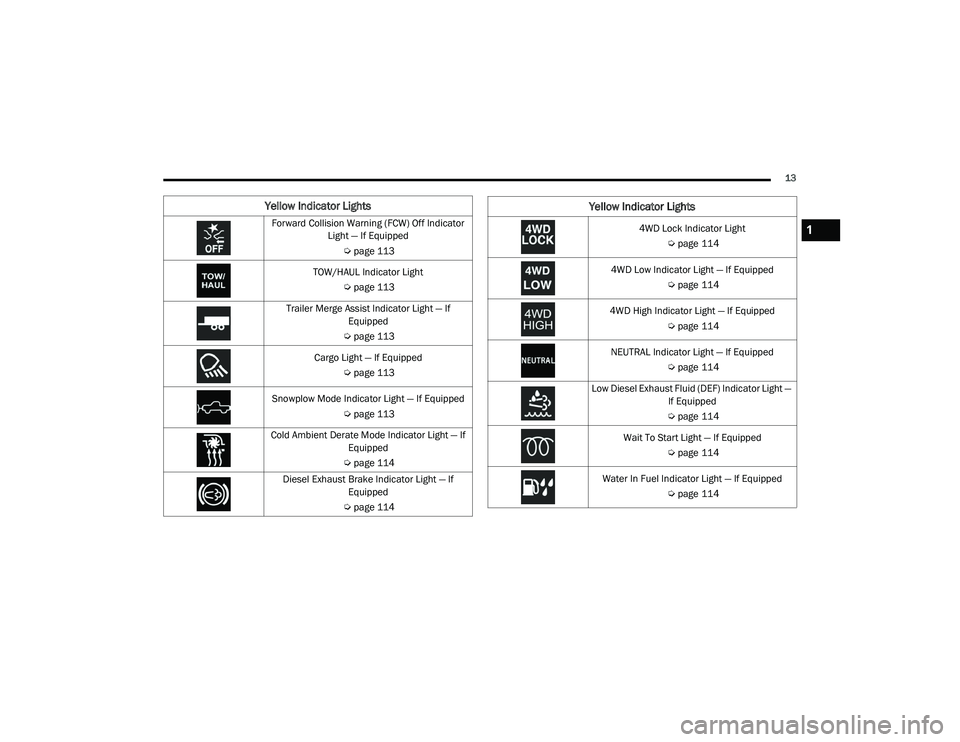
Yellow Indicator Lights
Forward Collision Warning (FCW) Off Indicator Light — If Equipped
Úpage 113
TOW/HAUL Indicator Light Úpage 113
Trailer Merge Assist Indicator Light — If Equipped
Ú page 113
Cargo Light — If Equipped Úpage 113
Snowplow Mode Indicator Light — If Equipped Úpage 113
Cold Ambient Derate Mode Indicator Light — If Equipped
Ú page 114
Diesel Exhaust Brake Indicator Light — If Equipped
Ú page 1144WD Lock Indicator Light
Úpage 114
4WD Low Indicator Light — If Equipped Úpage 114
4WD High Indicator Light — If Equipped Úpage 114
NEUTRAL Indicator Light — If Equipped Úpage 114
Low Diesel Exhaust Fluid (DEF) Indicator Light — If Equipped
Ú page 114
Wait To Start Light — If Equipped Úpage 114
Water In Fuel Indicator Light — If Equipped Úpage 114
Yellow Indicator Lights
1
21_DPF_OM_EN_USC_t.book Page 13
Page 18 of 463
16GETTING TO KNOW YOUR VEHICLE
When the doors are unlocked, the turn signals
will flash and the illuminated entry system will
be activated. When the doors are locked, the
turn signals will flash and the horn will chirp.
All doors can be programmed to unlock on the
first push of the unlock button. The horn chirp
when the lock button is pushed can be
programmed on/off within Uconnect Settings
Ú
page 228.
Replacing The Battery In The Key Fob
The replacement battery model is one CR2450
battery.
NOTE:
Customers are recommended to use a
battery obtained from Mopar. Aftermarket
coin battery dimensions may not meet the
original OEM coin battery dimensions.
Perchlorate Material — special handling
may apply. See
www.dtsc.ca.gov/hazard -
ouswaste/perchlorate
for further information.
Do not touch the battery terminals that are
on the back housing or the printed circuit
board.
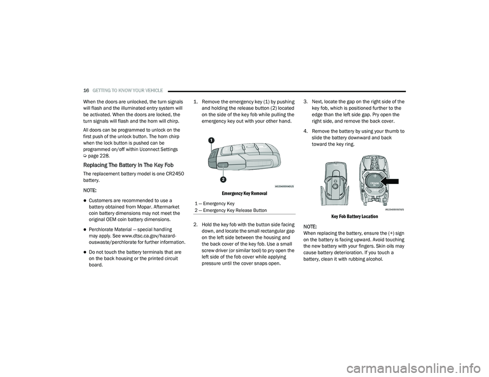
1. Remove the emergency key (1) by pushing
and holding the release button (2) located
on the side of the key fob while pulling the
emergency key out with your other hand.
Emergency Key Removal
2. Hold the key fob with the button side facing down, and locate the small rectangular gap
on the left side between the housing and
the back cover of the key fob. Use a small
screw driver (or similar tool) to pry open the
left side of the fob cover while applying
pressure until the cover snaps open. 3. Next, locate the gap on the right side of the
key fob, which is positioned further to the
edge than the left side gap. Pry open the
right side, and remove the back cover.
4. Remove the battery by using your thumb to slide the battery downward and back
toward the key ring.
Key Fob Battery Location
NOTE:
When replacing the battery, ensure the (+) sign
on the battery is facing upward. Avoid touching
the new battery with your fingers. Skin oils may
cause battery deterioration. If you touch a
battery, clean it with rubbing alcohol.
1 — Emergency Key
2 — Emergency Key Release Button
21_DPF_OM_EN_USC_t.book Page 16
Page 31 of 463
GETTING TO KNOW YOUR VEHICLE29
STEERING WHEEL
TILT STEERING COLUMN
This feature allows you to tilt the steering
column upward or downward. The tilt lever is
located on the steering column, below the
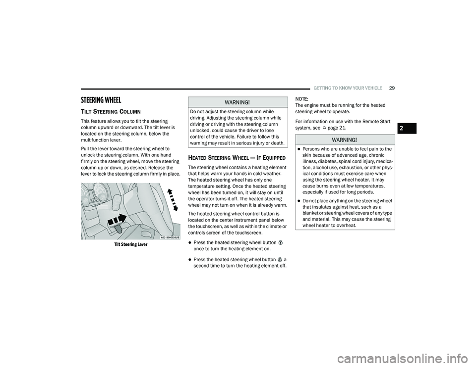
multifunction lever.
Pull the lever toward the steering wheel to
unlock the steering column. With one hand
firmly on the steering wheel, move the steering
column up or down, as desired. Release the
lever to lock the steering column firmly in place.
Tilt Steering Lever
HEATED STEERING WHEEL — IF EQUIPPED
The steering wheel contains a heating element
that helps warm your hands in cold weather.
The heated steering wheel has only one
temperature setting. Once the heated steering
wheel has been turned on, it will stay on until
the operator turns it off. The heated steering
wheel may not turn on when it is already warm.
The heated steering wheel control button is
located on the center instrument panel below
the touchscreen, as well as within the climate or
controls screen of the touchscreen.
Press the heated steering wheel button
once to turn the heating element on.
Press the heated steering wheel button a
second time to turn the heating element off. NOTE:
The engine must be running for the heated
steering wheel to operate.
For information on use with the Remote Start
system, see Ú
page 21.
WARNING!
Do not adjust the steering column while
driving. Adjusting the steering column while
driving or driving with the steering column
unlocked, could cause the driver to lose
control of the vehicle. Failure to follow this
warning may result in serious injury or death.
WARNING!
Persons who are unable to feel pain to the
skin because of advanced age, chronic
illness, diabetes, spinal cord injury, medica -
tion, alcohol use, exhaustion, or other phys -
ical conditions must exercise care when
using the steering wheel heater. It may
cause burns even at low temperatures,
especially if used for long periods.
Do not place anything on the steering wheel
that insulates against heat, such as a
blanket or steering wheel covers of any type
and material. This may cause the steering
wheel heater to overheat.
2
21_DPF_OM_EN_USC_t.book Page 29
Page 40 of 463

38GETTING TO KNOW YOUR VEHICLE
The front ventilated seats control buttons are
located on the center instrument panel below
the touchscreen, and are also located within the
climate or controls screen of the touchscreen.
Press the ventilated seat button once to
choose HI.
Press the ventilated seat button a second
time to choose MED.
Press the ventilated seat button a third
time to choose LO.
Press the ventilated seat button a fourth
time to turn the ventilation off.
NOTE:
The engine must be running for the ventilated
seats to operate.
For information on use with the Remote Start
system, see Ú page 21.
HEAD RESTRAINTS
Head restraints are designed to reduce the risk
of injury by restricting head movement in the
event of a rear impact. Head restraints should
be adjusted so that the top of the head restraint
is located above the top of your ear.
NOTE:
Do not reverse the head restraints (making the
rear of the head restraint face forward) in an
attempt to gain additional clearance to the back
of your head.
Front Head Restraints
Four-Way Head Restraints — If Equipped
Your vehicle may be equipped with front
four-way driver and passenger head restraints.
To raise the head restraint, pull upward on the head
restraint. To lower the head restraint, push the
adjustment button, located at the base of the head
restraint, and push downward on the head restraint.
To adjust the head restraint forward, pull the
top of the head restraint toward the front of the
vehicle as desired and release. To adjust the
head restraint rearward, pull the top of the head
restraint to the forward most position and
release. The head restraint will return to the
rear most position.
Forward Adjustment
WARNING!
All occupants, including the driver, should
not operate a vehicle or sit in a vehicle’s seat
until the head restraints are placed in their
proper positions in order to minimize the risk
of neck injury in the event of a crash.
Head restraints should never be adjusted
while the vehicle is in motion. Driving a
vehicle with the head restraints improperly
adjusted or removed could cause serious
injury or death in the event of a collision.
21_DPF_OM_EN_USC_t.book Page 38
Page 41 of 463

GETTING TO KNOW YOUR VEHICLE39
NOTE:
Four-way head restraints have seven tilt/
locking positions. When pulling fully forward,
the head restraint will spring back to the
untilted, rearward most position when released.
Two-Way Head Restraints — If Equipped
Your vehicle may be equipped with front
two-way driver and passenger head restraints.
To raise the head restraint, pull upward on the
head restraint. To lower the head restraint,
push the adjustment button, located at the
base of head restraint, and push downward
on the head restraint.
Head Restraint Adjustment Button Location
NOTE:
If your vehicle is equipped with a front bench
seat, the center head restraint is not adjustable
or removable.
Front Head Restraint Removal
To remove the head restraint, push the
adjustment button and the release button
while pulling upward on the whole assembly.
To reinstall the head restraint, put the head
restraint posts into the holes and adjust it to the
appropriate height.
Rear Head Restraint Adjustment
The rear seats are equipped with adjustable
and removable head restraints. To raise the
head restraint, pull upward on the head
restraint. To lower the head restraint, push the
adjustment button located on the base of the
head restraint and push downward on the head
restraint.
WARNING!
All occupants, including the driver, should
not operate a vehicle or sit in a vehicle’s seat
until the head restraints are placed in their
proper positions in order to minimize the risk
of neck injury in the event of a crash.
Head restraints should never be adjusted
while the vehicle is in motion. Driving a
vehicle with the head restraints improperly
adjusted or removed could cause serious
injury or death in the event of a collision.
WARNING!
A loose head restraint thrown forward in a
collision or hard stop could cause serious
injury or death to occupants of the vehicle.
Always securely stow removed head
restraints in a location outside the occu
-
pant compartment.
ALL the head restraints MUST be rein -
stalled in the vehicle to properly protect
the occupants. Follow the re-installation
instructions above prior to operating the
vehicle or occupying a seat.
2
21_DPF_OM_EN_USC_t.book Page 39
Page 42 of 463
40GETTING TO KNOW YOUR VEHICLE
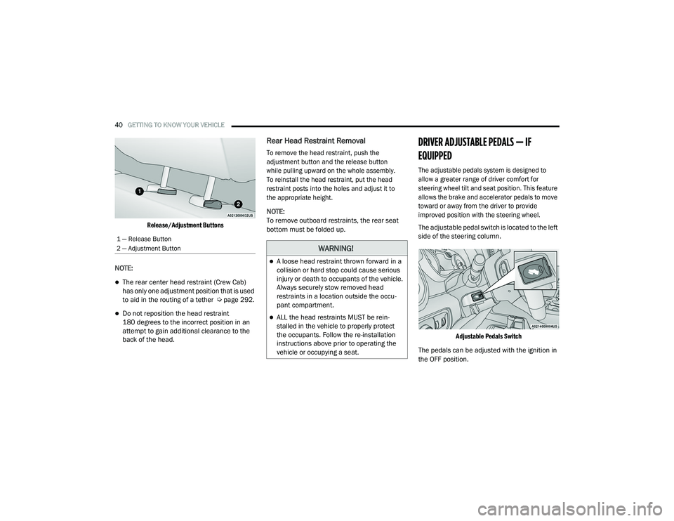
Release/Adjustment Buttons
NOTE:
The rear center head restraint (Crew Cab)
has only one adjustment position that is used
to aid in the routing of a tether Ú page 292.
Do not reposition the head restraint
180 degrees to the incorrect position in an
attempt to gain additional clearance to the
back of the head.
Rear Head Restraint Removal
To remove the head restraint, push the
adjustment button and the release button
while pulling upward on the whole assembly.
To reinstall the head restraint, put the head
restraint posts into the holes and adjust it to
the appropriate height.
NOTE:
To remove outboard restraints, the rear seat
bottom must be folded up.
DRIVER ADJUSTABLE PEDALS — IF
EQUIPPED
The adjustable pedals system is designed to
allow a greater range of driver comfort for
steering wheel tilt and seat position. This feature
allows the brake and accelerator pedals to move
toward or away from the driver to provide
improved position with the steering wheel.
The adjustable pedal switch is located to the left
side of the steering column.
Adjustable Pedals Switch
The pedals can be adjusted with the ignition in
the OFF position.
1 — Release Button
2 — Adjustment Button
WARNING!
A loose head restraint thrown forward in a
collision or hard stop could cause serious
injury or death to occupants of the vehicle.
Always securely stow removed head
restraints in a location outside the occu -
pant compartment.
ALL the head restraints MUST be rein -
stalled in the vehicle to properly protect
the occupants. Follow the re-installation
instructions above prior to operating the
vehicle or occupying a seat.
21_DPF_OM_EN_USC_t.book Page 40
Page 43 of 463
GETTING TO KNOW YOUR VEHICLE41
The pedals cannot be adjusted when the vehicle is
in REVERSE or when the Cruise Control system is on.
If there is an attempt to adjust the pedals when the
system is locked out, the following messages will
appear (on vehicles equipped with an instrument
cluster display):
Adjustable Pedal Disabled — Cruise Control
Engaged
Adjustable Pedal Disabled — Vehicle In
Reverse
NOTE:
Always adjust the pedals to a position that
allows full movement of the pedal.
Further small adjustments may be necessary
to find the best possible seat/pedal position.
For vehicles equipped with Driver Memory
Settings, you can use your remote keyless
entry key fob or the memory switch on the
driver’s door trim panel to return the adjust -
able pedals to saved positions Ú page 32.
MIRRORS
INSIDE REARVIEW MIRROR
Manual Mirror — If Equipped
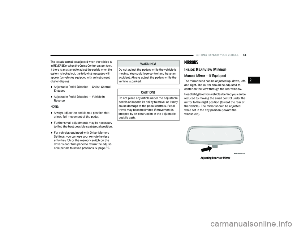
The mirror head can be adjusted up, down, left,
and right. The mirror should be adjusted to
center on the view through the rear window.
Headlight glare from vehicles behind you can be
reduced by moving the small control under the
mirror to the night position (toward the rear of
the vehicle). The mirror should be adjusted
while set in the day position (toward the
windshield).
Adjusting Rearview Mirror
WARNING!
Do not adjust the pedals while the vehicle is
moving. You could lose control and have an
accident. Always adjust the pedals while the
vehicle is parked.
CAUTION!
Do not place any article under the adjustable
pedals or impede its ability to move, as it may
cause damage to the pedal controls. Pedal
travel may become limited if movement is
stopped by an obstruction in the adjustable
pedal's path.
2
21_DPF_OM_EN_USC_t.book Page 41