brake sensor RAM CHASSIS CAB 2023 Owners Manual
[x] Cancel search | Manufacturer: RAM, Model Year: 2023, Model line: CHASSIS CAB, Model: RAM CHASSIS CAB 2023Pages: 444, PDF Size: 20.51 MB
Page 7 of 444
5
ENGINE BREAK-IN RECOMMENDATIONS —
DIESEL ENGINE .................................................... 128
PARKING BRAKE ................................................ 128
DIESEL EXHAUST BRAKE (ENGINE BRAKING) .. 129
AUTOMATIC TRANSMISSION.............................. 130 Ignition Park Interlock ................................... 131Brake/Transmission Shift Interlock (BTSI)
System .......................................................... 131
8-Speed Automatic Transmission —
If Equipped .................................................... 132
6-Speed Automatic Transmission —
If Equipped .................................................... 135
AUXILIARY SWITCHES — IF EQUIPPED ............. 139
FOUR-WHEEL DRIVE OPERATION —
IF EQUIPPED ........................................................ 140
Electronically Shifted Transfer Case
(8-Speed Transmission) — If Equipped ....... 140Electronically Shifted Transfer Case
(6-Speed Transmission) —
If Equipped..................................................... 143
Manually Shifted Transfer Case —
If Equipped..................................................... 145
LIMITED-SLIP DIFFERENTIAL ............................ 147
POWER TAKE OFF (PTO) OPERATION —
IF EQUIPPED ........................................................ 147
HYDRAULIC POWER STEERING .........................148
Power Steering Fluid Check .......................... 148
CRUISE CONTROL SYSTEMS — IF EQUIPPED .... 148
Cruise Control ............................................... 149
Adaptive Cruise Control (ACC) ...................... 150 PARKSENSE FRONT/REAR PARK ASSIST —
IF EQUIPPED ....................................................... 159
ParkSense Sensors ....................................... 159
ParkSense Warning Display ......................... 159
ParkSense Display ........................................ 159Enabling And Disabling ParkSense .............. 162
Service The ParkSense Park Assist System ...162
Cleaning The ParkSense System ................. 162
ParkSense System Usage Precautions........ 162
LANESENSE — IF EQUIPPED ............................. 163
LaneSense Operation ................................... 163Turning LaneSense On Or Off ....................... 164
LaneSense Warning Message ...................... 164Changing LaneSense Status ........................ 166
Turn Signal Activated Blind Spot Assist —
If Equipped..................................................... 166
PARKVIEW REAR BACK UP CAMERA............... 166
SURROUND VIEW CAMERA SYSTEM —
IF EQUIPPED ........................................................ 168
TRAILER CAMERAS — IF EQUIPPED ................. 173 Trailer Surround View Camera System —
If Equipped..................................................... 173AUX Camera — If Equipped ........................... 176
ENGINE RUNAWAY ............................................. 176
REFUELING THE VEHICLE—
GASOLINE ENGINE ............................................. 177
Loose Fuel Filler Cap Message ................... 177
REFUELING THE VEHICLE — DIESEL ENGINE... 177
Diesel Exhaust Fluid...................................... 178 VEHICLE LOADING .............................................. 180
Gross Vehicle Weight Rating (GVWR) ......... 180
Payload .......................................................... 180Gross Axle Weight Rating (GAWR)................ 180Tire Size ......................................................... 181
Rim Size ......................................................... 181
Inflation Pressure .......................................... 181Curb Weight ................................................... 181
Loading .......................................................... 181
TRAILER TOWING ................................................ 181
Common Towing Definitions......................... 181
Trailer Hitch Type and Maximum Trailer
Weight ............................................................ 185
Trailer Towing Weights (Maximum Traile
r Weight Ratings) .......................................... 186Trailer And Tongue Weight .......................... 186
Towing Requirements .................................. 186Towing Tips ................................................... 192
SNOWPLOW — IF EQUIPPED.............................. 192
Before Plowing .............................................. 192
Snowplow Prep Package Model Availability....193
Over The Road Operation With Snowplow
Attached......................................................... 193
Operating Tips ............................................... 193General Maintenance ................................... 193
23_DPF_OM_EN_USC_t.book Page 5
Page 97 of 444
GETTING TO KNOW YOUR INSTRUMENT PANEL95
Pitch And Roll
Displays the pitch and roll of the vehicle in
the graphic with the angle number on the
screen.
NOTE:When vehicle speed becomes too high to display
the pitch and roll, “- -” will display in place of the
numbers, and the graphic will be greyed out. A
message indicating the necessary speed for the
feature to become available will also display.
Fuel Economy — If Equipped
Push and release the up or down arrow
button until the Fuel Economy menu item is
highlighted in the instrument cluster display. Push
and Hold the right arrow button to reset
Average Fuel Economy.
Current Fuel Economy Gauge
Average Fuel Economy Value
Range To Empty
Fuel Tank Levels — If Equipped
Trip A/Trip B
Push and release the up or down arrow
button until the Trip menu item is highlighted in the
instrument cluster display. Push and release the
right arrow button to enter the submenus of Trip A and Trip B. The Trip A or Trip B information
will display the following:
Distance
Average Fuel Economy
Elapsed Time
Push and hold right arrow button to reset all
information.
Navigation — If Equipped
Push and release the up or down arrow
button until the Navigation display title is
highlighted in the instrument cluster display, “Hold
OK to Start Route” will display when no active route
is set. “Hold OK to Cancel Route” will display when
active route is set. Use the left or right arrow
button to zoom in or out on the display
Ú page 199.
Trailer Tow
Push and release the up or down arrow
button until the Trailer Tow menu item is
highlighted in the instrument cluster display. Push
and release the right or left arrow button to
cycle through the following trailer tow information:
Trip (trailer specific) Distance: Push and hold
the OK button to reset the distance.
Integrated Trailer Brake Module (ITBM):
Braking Output
Trailer Type
ITBM Gain
Trailer Tire Pressure Monitoring: The Instrument
Cluster Display will display the Trailer Tire Pres -
sure for a connected trailer with sensors that
match the active trailer profile. When a low tire
is present, the low tire value will be displayed in
red, and the affected low tire will have a red
glow. “Trailer Tire Low“ will be displayed on the
center bottom of the Instrument Cluster Display
screen.
Trailer Light Check – If Equipped: Push and hold
the OK button to begin the Trailer Light Test
sequence Ú page 190.
For vehicles equipped with Blind Spot Monitoring
(BSM):
When a Trailer Brake signal is detected, a
pop-up message will appear in the cluster
requiring user to select trailer type.
If a conventional trailer is selected, the BSM
operation will function as normal.
If Gooseneck/5th Wheel trailer is selected
BSM will be disabled due to unsupported
trailer type.
If no selection is made, the BSM system will
remain on until a selection is chosen.
3
23_DPF_OM_EN_USC_t.book Page 95
Page 110 of 444

108GETTING TO KNOW YOUR INSTRUMENT PANEL
Anti-Lock Brake System (ABS) Warning
Light
This warning light monitors the ABS. The
light will turn on when the ignition is
placed in the ON/RUN or ACC/ON/RUN
position and may stay on for as long as
four seconds.
If the ABS light remains on or turns on while
driving, then the Anti-Lock portion of the brake
system is not functioning and service is required as
soon as possible. However, the conventional brake
system will continue to operate normally,
assuming the Brake Warning Light is not also on. If the ABS light does not turn on when the ignition
is placed in the ON/RUN or ACC/ON/RUN position,
have the brake system inspected by an authorized
dealer.
Service Forward Collision Warning (FCW)
Light — If Equipped
This warning light will illuminate to
indicate a fault in the Forward Collision
Warning System. Contact an authorized
dealer for service Ú
page 278.
Service LaneSense Warning Light —
If Equipped
This warning light will illuminate when the
LaneSense system is not operating and
requires service. Please see an
authorized dealer.
Service 4WD Warning Light — If Equipped
This warning light will illuminate to signal
a fault with the 4WD system. If the light
stays on or comes on during driving, it
means that the 4WD system is not
functioning properly and that service is required.
We recommend you drive to the nearest service
center and have the vehicle serviced immediately.
Cruise Control Fault Warning Light
This warning light will illuminate to
indicate the Cruise Control System is not
functioning properly and service is
required. Contact an authorized dealer.
YELLOW INDICATOR LIGHTS
Forward Collision Warning (FCW) Off
Indicator Light — If Equipped
This indicator light illuminates to indicate
that Forward Collision Warning is off
Ú page 277.
TOW/HAUL Indicator Light
This indicator light will illuminate when
TOW/HAUL mode is selected.
Trailer Merge Assist Indicator Light —
If Equipped
This indicator light will illuminate to
indicate when Trailer Merge Assist has
been activated.
Cargo Indicator Light — If Equipped
This indicator light will illuminate when
the cargo light is activated by pushing the
cargo light button on the headlight
switch.
CAUTION!
The TPMS has been optimized for the original
equipment tires and wheels. TPMS pressures
and warning have been established for the tire
size equipped on your vehicle. Undesirable
system operation or sensor damage may result
when using replacement equipment that is not
of the same size, type, and/or style. Aftermarket
wheels can cause sensor damage. Using
aftermarket tire sealants may cause the Tire
Pressure Monitoring System (TPMS) sensor to
become inoperable. After using an aftermarket
tire sealant it is recommended that you take
your vehicle to an authorized dealer to have your
sensor function checked.
23_DPF_OM_EN_USC_t.book Page 108
Page 152 of 444

150STARTING AND OPERATING
To Accelerate For Passing
While the Cruise Control is set, press the
accelerator to pass as you would normally. When
the pedal is released, the vehicle will return to the
set speed.
USING CRUISE CONTROL ON HILLS
The transmission may downshift on hills to
maintain the vehicle set speed.
The Cruise Control system maintains speed up and
down hills. A slight speed change on moderate hills
is normal. On steep hills, a greater speed loss or
gain may occur so it may be preferable to drive
without Cruise Control.
To Resume Speed
To resume a previously set speed, push the RES
button and release. Resume can be used at any
speed above 20 mph (32 km/h).
To Deactivate
A tap on the brake pedal, pushing the CANC
(cancel) button, or normal brake pressure while
slowing the vehicle will deactivate the Cruise
Control system without erasing the set speed from
memory.
The following conditions will also deactivate the
Cruise Control system without erasing the set
speed from memory:
Vehicle parking brake is applied
Stability event occurs
Gear selector is moved out of DRIVE
Engine overspeed occurs
Pushing the on/off button or placing the ignition in
the OFF position, erases the set speed from
memory.
ADAPTIVE CRUISE CONTROL (ACC)
Adaptive Cruise Control (ACC) increases the driving
convenience provided by Cruise Control while
traveling on highways and major roadways.
However, it is not a safety system and not designed
to prevent collisions. The Cruise Control function
performs differently Ú page 149.
ACC will allow you to keep Cruise Control engaged
in light to moderate traffic conditions without the
constant need to reset your speed. ACC utilizes a
radar sensor and a forward facing camera
designed to detect a vehicle directly ahead of you
to maintain a set speed.
NOTE:
If the ACC sensor detects a vehicle ahead, ACC
will apply limited braking or acceleration (not to
exceed the original set speed) automatically to
maintain a preset following distance, while
matching the speed of the vehicle ahead.
Any chassis/suspension or tire size modifica -
tions to the vehicle will affect the performance
of the Adaptive Cruise Control and Forward Colli -
sion Warning system.
Fixed Speed Cruise Control (ACC not enabled)
will not detect vehicles directly ahead of you.
Always be aware of the feature selected
Ú page 427.
WARNING!
Cruise Control can be dangerous where the
system cannot maintain a constant speed. Your
vehicle could go too fast for the conditions, and
you could lose control and have an accident. Do
not use Cruise Control in heavy traffic or on
roads that are winding, icy, snow-covered or
slippery.
23_DPF_OM_EN_USC_t.book Page 150
Page 157 of 444

STARTING AND OPERATING155
Distance Settings
To increase the distance setting, push the
Distance Increase button and release. Each time
the button is pushed, the distance setting
increases by one bar (longer).
To decrease the distance setting, push the
Distance Decrease button and release. Each time
the button is pushed, the distance setting
decreases by one bar (shorter).
If there is no vehicle ahead, the vehicle will
maintain the set speed. If a slower moving vehicle
is detected in the same lane, the instrument
cluster displays the ACC Set With Target Detected Indicator Light, and the system adjusts vehicle
speed automatically to maintain the distance
setting, regardless of the set speed.
NOTE:If the vehicles Integrated Trailer Brake Module
(ITBM) detects a trailer is connected to the vehicle,
and ACC is enabled, the system will increase the
distance to the longest distance setting (four bars)
by default.
The vehicle will then maintain the set distance
until:
The vehicle ahead accelerates to a speed above
the set speed.
The vehicle ahead moves out of your lane or
view of the sensor.
The distance setting is changed.
The system disengages.
The maximum braking applied by ACC is limited;
however, the driver can always apply the brakes
manually, if necessary.
NOTE:The brake lights will illuminate whenever the ACC
system applies the brakes.
A Proximity Warning will alert the driver if ACC
predicts that its maximum braking level is not
sufficient to maintain the set distance. If this
occurs, a visual alert “BRAKE!” will flash in the
instrument cluster display and a chime will sound while ACC continues to apply its maximum braking
capacity.
NOTE:The “BRAKE!” screen in the instrument cluster
display is a warning for the driver to take action
and does not mean that the Forward Collision
Warning system is applying the brakes autono-
mously.
Overtake Aid
When driving with ACC engaged and following a
vehicle, the system will provide an additional
acceleration up to the ACC set speed to assist in
passing the vehicle. This additional acceleration is
triggered when the driver utilizes the left turn
signal and will only be active when passing on the
left hand side.
ACC Operation At Stop
If the ACC system brings your vehicle to a standstill
while following a vehicle ahead, your vehicle will
resume motion, without any driver interaction, if
the vehicle ahead starts moving within two
seconds of your vehicle coming to a standstill.
If the vehicle in front does not start moving within
two seconds of your vehicle coming to a standstill,
the ACC with Stop system will cancel and the
brakes will release. A cancel message will display
on the instrument cluster display and produce a
warning chime. The driver must now manually
operate the vehicle’s accelerator and brakes.
1 — Longest Distance Setting (Four Bars)
2 — Medium Distance Setting (Two Bars)
3 — Long Distance Setting (Three Bars)
4 — Short Distance Setting (One Bar)
4
23_DPF_OM_EN_USC_t.book Page 155
Page 158 of 444
156STARTING AND OPERATING
While ACC with Stop is holding your vehicle at a
standstill, if the driver seat belt is unbuckled or the
driver door is opened, the ACC with Stop system
will cancel and the brakes will release. A cancel
message will display on the instrument cluster
display and produce a warning chime. The driver
must now manually operate the vehicle’s
accelerator and brakes.
Display Warnings And Maintenance
“WIPE FRONT RADAR SENSOR IN FRONT OF
VEHICLE” WARNING
The “ACC/FCW Unavailable Wipe Front Radar
Sensor” warning will display and a chime will
sound when conditions temporarily limit system
performance.
This most often occurs at times of poor visibility,
such as in snow or heavy rain. The ACC system may
also become temporarily blinded due to
obstructions, such as mud, dirt or ice. In these
cases, the instrument cluster display will display “ACC/FCW Unavailable Wipe Front Radar Sensor”
and the system will deactivate.
This message can sometimes be displayed while
driving in highly reflective areas (i.e. ice and snow,
or tunnels with reflective tiles). The ACC system will
recover after the vehicle has left these areas.
Under rare conditions, when the radar is not
tracking any vehicles or objects in its path this
warning may temporarily occur.
NOTE:If the “ACC/FCW Unavailable Wipe Front Radar
Sensor” warning is active, Fixed Speed Cruise
Control is still available.
If weather conditions are not a factor, the driver
should examine the sensor. It may require cleaning
or removal of an obstruction. The sensor is located
in the camera in the center of the windshield, on
the forward side of the rearview mirror.
To keep the ACC system operating properly, it is
important to note the following maintenance
items:
Always keep the sensor clean. Carefully clear
the windshield.
Do not remove any screws from the sensor.
Doing so could cause an ACC system malfunc
-
tion or failure and require a sensor realignment.
Do not attach or install any accessories near the
sensor, including transparent material or after -market grilles. Doing so could cause an ACC
system failure or malfunction.
When the condition that deactivated the system is
no longer present, the system will return to the
“Adaptive Cruise Control Off” state and will resume
function by simply reactivating it.
NOTE:
If the “ACC/FCW Unavailable Wipe Front Radar
Sensor” message occurs frequently (e.g. more
than once on every trip) without any snow, rain,
mud, or other obstruction, have the radar
sensor realigned at an authorized dealer.
Installing a snowplow, front-end protector, an
aftermarket grille or modifying the grille is not
recommended. Doing so may block the sensor
and inhibit ACC/FCW operation.
“CLEAN FRONT WINDSHIELD” WARNING
The “ACC/FCW Limited Functionality Clean Front
Windshield” warning will display and a chime will
sound when conditions temporarily limit system
performance. This most often occurs at times of
poor visibility, such as in snow or heavy rain and
fog. The ACC system may also become temporarily
blinded due to obstructions, such as mud, dirt, or
ice on windshield, driving directly into the sun and
fog on the inside of glass. In these cases, the
instrument cluster display will show “ACC/FCW
Limited Functionality Clean Front Windshield” and
the system will have degraded performance.
WARNING!
When the ACC system is resumed, the driver
must ensure that there are no pedestrians,
vehicles or objects in the path of the vehicle.
Failure to follow these warnings can result in a
collision and death or serious personal injury.
23_DPF_OM_EN_USC_t.book Page 156
Page 164 of 444

162STARTING AND OPERATING
NOTE:ParkSense will reduce the volume of the radio, if
on, when the system is sounding an audio tone.
ParkSense Camera Activation
If the ParkSense system detects an obstacle, a
camera image will display in the radio. The camera
will continue to display as long as the ParkSense
system continues to detect an object. This can be
turned on or off in the Uconnect system
Úpage 199.
Front Park Assist Audible Alerts
ParkSense will turn off the Front Park Assist
audible alert (chime) after approximately three
seconds when an obstacle has been detected, the
vehicle is stationary, and brake pedal is applied.
Adjustable Chime Volume Settings
The Front and Rear chime volume settings are
programmable through the Uconnect system
Ú page 199.
ENABLING AND DISABLING PARKSENSE
Front ParkSense can be enabled and
disabled with the Front ParkSense
switch.
Rear ParkSense can be enabled and disabled with
the Rear ParkSense switch.
When the gear selector is moved to REVERSE and
the Front or Rear system is disabled, the instrument cluster display will show a vehicle
graphic with an “Off” message overlay over the
system that is off (Front or Rear system). This
vehicle graphic will be displayed for as long as the
vehicle is in REVERSE.
The Front or Rear ParkSense switch LED will be on
when Front or Rear ParkSense is disabled or
requires service. The Front or Rear ParkSense
switch LED will be off when the Front or Rear
system is enabled. If the Front or Rear ParkSense
switch is pushed, and the system requires service,
the Front or Rear ParkSense switch LED will blink
momentarily, and then the LED will be on.
SERVICE THE PARKSENSE PARK ASSIST
S
YSTEM
During vehicle start-up, when the Front/Rear
ParkSense System has detected a faulted
condition, the instrument cluster display will show
the "Front/Rear ParkSense Unavailable Service
Required" or the "Front/Rear ParkSense
Unavailable Wipe Sensors" message.
When the gear selector is moved into REVERSE, a
vehicle graphic will show in the instrument cluster
display, along with the display overlay “Wipe
Sensors.” If the system needs service, the display
overlay will read “Service.” Under this condition,
ParkSense will not operate. If "Front/Rear ParkSense Unavailable Wipe
Sensors" appears in the instrument cluster display
make sure the outer surface and the underside of
the rear fascia/bumper is clean and clear of snow,
ice, mud, dirt or other obstruction, and then cycle
the ignition. If the message continues to appear,
see an authorized dealer.
If "Front/Rear ParkSense Unavailable Service
Required" appears in the instrument cluster
display, see an authorized dealer.
CLEANING THE PARKSENSE SYSTEM
Clean the ParkSense sensors with water, car wash
soap and a soft cloth. Do not use rough or hard
cloths. Do not scratch or poke the sensors.
Otherwise, you could damage the sensors.
PARKSENSE SYSTEM USAGE
P
RECAUTIONS
NOTE:
Ensure that the front and rear bumpers are free
of snow, ice, mud, dirt and debris to keep the
ParkSense system operating properly.
Jackhammers, large trucks, and other vibra -
tions could affect the performance of
ParkSense.
23_DPF_OM_EN_USC_t.book Page 162
Page 274 of 444
272SAFETY
Brake System Warning Light
The red Brake System Warning Light will turn on
when the ignition is placed in the ON/RUN mode
and may stay on for as long as four seconds.
If the Brake System Warning Light remains on or
comes on while driving, it indicates that the brake
system is not functioning properly and that
immediate service is required. If the Brake System
Warning Light does not come on when the ignition
is placed in the ON/RUN mode, have the light
repaired as soon as possible.
Electronic Brake Force Distribution (EBD)
EBD manages the distribution of the braking
torque between the front and rear axles by limiting
braking pressure to the rear axle. This is done to
prevent overslip of the rear wheels to avoid vehicle
instability, and to prevent the rear axle from
entering ABS before the front axle.
Electronic Roll Mitigation (ERM)
ERM anticipates the potential for wheel lift by
monitoring the driver’s steering wheel input and
the speed of the vehicle. When ERM determines
that the rate of change of the steering wheel angle
and vehicle’s speed are sufficient to potentially
cause wheel lift, it then applies the appropriate
brake and may also reduce engine power to lessen
the chance that wheel lift will occur. ERM can only
reduce the chance of wheel lift occurring during
severe or evasive driving maneuvers; it cannot prevent wheel lift due to other factors, such as
road conditions, leaving the roadway, or striking
objects or other vehicles.
NOTE:ERM is disabled any time the ESC is in “Full Off”
mode (if equipped). For a complete explanation of
the available ESC modes, see Ú
page 272.
Electronic Stability Control (ESC)
ESC enhances directional control and stability of
the vehicle under various driving conditions. ESC
corrects for oversteering or understeering of the
vehicle by applying the brake of the appropriate
wheel(s) to counteract the above conditions.
Engine power may also be reduced to help the
vehicle maintain the desired path.
Oversteer — when the vehicle is turning more
than appropriate for the steering wheel position.
Understeer — when the vehicle is turning less
than appropriate for the steering wheel position.
ESC uses sensors in the vehicle to determine the
vehicle path intended by the driver and compares
it to the actual path of the vehicle. When the actual
path does not match the intended path, ESC
applies the brake of the appropriate wheel to
assist in counteracting the oversteer or understeer
condition.
The ESC Activation/Malfunction Indicator Light
located in the instrument cluster will start to flash
as soon as the ESC system becomes active. The
ESC Activation/Malfunction Indicator Light also
flashes when the TCS is active. If the ESC
Activation/Malfunction Indicator Light begins to
flash during acceleration, ease up on the
accelerator and apply as little throttle as possible.
Be sure to adapt your speed and driving to the
prevailing road conditions.
WARNING!
Many factors, such as vehicle loading, road
conditions and driving conditions, influence the
chance that wheel lift or rollover may occur. ERM
cannot prevent all wheel lift or rollovers,
especially those that involve leaving the roadway
or striking objects or other vehicles. The
capabilities of an ERM-equipped vehicle must
never be exploited in a reckless or dangerous
manner which could jeopardize the user's safety
or the safety of others.
23_DPF_OM_EN_USC_t.book Page 272
Page 279 of 444

SAFETY277
Towing With HSA
HSA will also provide assistance to mitigate roll
back while towing a trailer.
Ready Alert Braking (RAB)
RAB may reduce the time required to reach full
braking during emergency braking situations. It
anticipates when an emergency braking situation
may occur by monitoring how fast the throttle is
released by the driver. The Electronic Brake
Control system will prepare the brake system for a
panic stop.
Traction Control System (TCS)
The TCS monitors the amount of wheel spin of
each of the driven wheels. If wheel spin is
detected, the TCS may apply brake pressure to the
spinning wheel(s) and/or reduce engine power to
provide enhanced acceleration and stability. A
feature of the TCS, Brake Limited Differential (BLD)
functions similarly to a limited slip differential and
controls the wheel spin across a driven axle. If one
wheel on a driven axle is spinning faster than the
other, the system will apply the brake of the
spinning wheel. This will allow more engine power
to be applied to the wheel that is not spinning. BLD
may remain enabled even if TCS and Electronic
Stability Control (ESC) are in reduced modes.
Trailer Sway Control (TSC)
TSC uses sensors in the vehicle to recognize an
excessively swaying trailer and will take the
appropriate actions to attempt to stop the sway.
NOTE:TSC cannot stop all trailers from swaying. Always
use caution when towing a trailer and follow the
trailer tongue weight recommendations
Úpage 181. When TSC is functioning, the ESC Activation/
Malfunction Indicator Light will flash, the engine
power may be reduced and you may feel the
brakes being applied to individual wheels to
attempt to stop the trailer from swaying. TSC is
disabled when the ESC system is in the “Partial
Off” or “Full Off” modes.
AUXILIARY DRIVING SYSTEMS
BLIND SPOT ASSIST CAMERAS —
I
F EQUIPPED
Blind Spot Assist Cameras
There are cameras located in the exterior mirrors
to assist in blind spot detection. Refer to
Ú page 166 to learn more about how the cameras
function with turn signal engagement or refer to
Ú page 168 to learn how to activate the cameras
through the Camera's screen.
WARNING!
If you use a trailer brake controller with your
trailer, the trailer brakes may be activated and
deactivated with the brake switch. If so, there
may not be enough brake pressure to hold
both the vehicle and the trailer on a hill when
the brake pedal is released. In order to avoid
rolling down an incline while resuming accel -
eration, manually activate the trailer brake or
apply more vehicle brake pressure prior to
releasing the brake pedal.
HSA is not a parking brake. Always apply the
parking brake fully when exiting your vehicle. Also,
be certain to place the transmission in PARK.
Failure to follow these warnings can result in a
collision or serious personal injury.
WARNING!
If TSC activates while driving, slow the vehicle
down, stop at the nearest safe location, and
adjust the trailer load to eliminate trailer sway.
6
23_DPF_OM_EN_USC_t.book Page 277
Page 280 of 444
278SAFETY
FORWARD COLLISION WARNING (FCW)
W
ITH MITIGATION — IF EQUIPPED
FCW with Mitigation provides the driver with
audible warnings, visual warnings (within the
instrument cluster display), and may apply a brake
jerk to warn the driver when it detects a potential
frontal collision. The warnings and limited braking
are intended to provide the driver with enough time
to react, avoid or mitigate the potential collision.
NOTE:FCW monitors the information from the forward
looking sensors as well as the Electronic Brake
Controller (EBC), to calculate the probability of a
forward collision. When the system determines
that a forward collision is probable, the driver will
be provided with audible and visual warnings as
well as a possible brake jerk warning.
If the driver does not take action based upon these
progressive warnings, then the system will provide
a limited level of active braking to help slow the
vehicle and mitigate the potential forward collision.
If the driver reacts to the warnings by braking and
the system determines that the driver intends to
avoid the collision by braking but has not applied
sufficient brake force, the system will compensate
and provide additional brake force as required. If an FCW with Mitigation event begins at a speed
below 32 mph (52 km/h), the system may provide
the maximum braking possible to mitigate the
potential forward collision. If the Forward Collision
Warning with Mitigation event stops the vehicle
completely, the system will hold the vehicle at
standstill for two seconds and then release the
brakes.
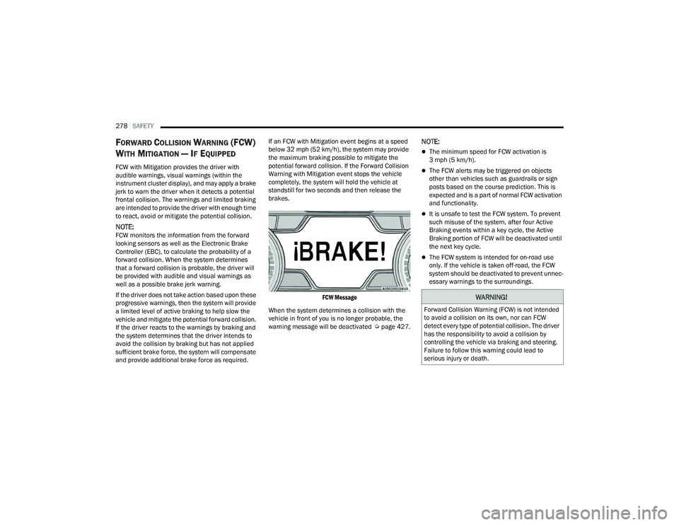
FCW Message
When the system determines a collision with the
vehicle in front of you is no longer probable, the
warning message will be deactivated Úpage 427.
NOTE:
The minimum speed for FCW activation is
3 mph (5 km/h).
The FCW alerts may be triggered on objects
other than vehicles such as guardrails or sign
posts based on the course prediction. This is
expected and is a part of normal FCW activation
and functionality.
It is unsafe to test the FCW system. To prevent
such misuse of the system, after four Active
Braking events within a key cycle, the Active
Braking portion of FCW will be deactivated until
the next key cycle.
The FCW system is intended for on-road use
only. If the vehicle is taken off-road, the FCW
system should be deactivated to prevent unnec -
essary warnings to the surroundings.
WARNING!
Forward Collision Warning (FCW) is not intended
to avoid a collision on its own, nor can FCW
detect every type of potential collision. The driver
has the responsibility to avoid a collision by
controlling the vehicle via braking and steering.
Failure to follow this warning could lead to
serious injury or death.
23_DPF_OM_EN_USC_t.book Page 278