stop start Ram ProMaster 2020 Owner's Guide
[x] Cancel search | Manufacturer: RAM, Model Year: 2020, Model line: ProMaster, Model: Ram ProMaster 2020Pages: 264, PDF Size: 10.11 MB
Page 107 of 264

STARTING AND OPERATING105
To Accelerate For Passing
Press the accelerator as you would normally.
When the pedal is released, the vehicle will
return to the set speed.
Using Speed Control On Hills
The transmission may downshift on hills to
maintain the vehicle set speed.
NOTE:
The Speed Control system maintains speed up
and down hills. A slight speed change on
moderate hills is normal.
On steep hills, a greater speed loss or gain may
occur so it may be preferable to drive without
Speed Control.
To Resume Speed
To resume a previously set speed, push the RES
button and release. Resume can be used at any
speed above 20 mph (32 km/h) up to the
maximum speed of 100 mph (160 km/h).
To Deactivate
A soft tap on the brake pedal, pushing the RES
button, or normal brake pressure while slowing
the vehicle will deactivate Speed Control
without erasing the set speed memory. Rotating
the center ring upward to turn the system off or
placing the ignition in the STOP (OFF/LOCK)
position erases the set speed memory.
PARKSENSE REAR PARK ASSIST — IF
EQUIPPED
The ParkSense Rear Park Assist system
provides an audible indication of the distance
between the rear fascia/bumper and a
detected obstacle when backing up (e.g. during
a parking maneuver). Refer to “ParkSense
System Usage Precautions” in this section for
limitations of this system and recommenda -
tions.
The ParkSense Rear Park Assist is automati -
cally activated when the transmission is placed
into REVERSE. As the distance from an obstacle
behind the vehicle decreases, the audible alert
becomes more frequent.
Interaction With Trailer Towing
The Rear Park Assist system is automatically
deactivated when a trailer is hitched to the
vehicle. The system will be automatically acti -
vated as soon as the trailer is removed.
WARNING!
Speed Control can be dangerous where the
system cannot maintain a constant speed.
Your vehicle could go too fast for the
conditions, and you could lose control and
have an accident. Do not use Speed Control
in heavy traffic or on roads that are winding,
icy, snow-covered or slippery.
5
20_VF_OM_EN_US_t.book Page 105
Page 110 of 264

108STARTING AND OPERATING
While audible signals are emitted, the audio
system is not muted.
The audible signal is turned off immediately if
the distance increases. The tone cycle remains
constant if the distance measured by the inner
sensors is constant. If this condition occurs for
the external sensors, the signal is turned off
after three seconds (stopping warnings during
maneuvers parallel to walls).
ParkSense Rear Park Assist Failure
Indications
A malfunction of the ParkSense Rear Park
Assist sensors or system is indicated, during
REVERSE gear engagement, by the instrument
panel warning icon.
The warning icon is illuminated and a
message is displayed in the instru -
ment cluster display (if equipped).
Refer to “Warning Lights And
Messages” in “Getting To Know Your Instru -
ment Panel” for further information.
The sensors and wiring are tested continuously
when the ignition is in the MAR (ACC/ON/RUN)
position. Failures are indicated immediately if
they occur when the system is on. Even if the system is able to identify that a
specific sensor is in failure condition, the instru
-
ment cluster display shall indicate that the Park-
Sense Rear Park Assist system is unavailable,
without reference to the sensor in failure condi -
tion. If even a single sensor fails, the entire
system must be disabled. The system is turned
off automatically.
Cleaning The ParkSense System
Clean the Rear Park Assist sensors with water,
car wash soap and a soft cloth. Do not use
rough or hard cloths. In washing stations, clean
sensors quickly keeping the vapor jet/high pres -
sure washing nozzles at least 4 inches (10 cm)
from the sensors. Do not scratch or poke the
sensors. Otherwise, you could damage the
sensors.
ParkSense Rear Park Assist System Usage
Precautions
NOTE:
Ensure that the outer surface and the under -
side of the rear bumper is clean and clear of
snow, ice, mud, dirt or other obstruction to
keep the Rear Park Assist system operating
properly.
Jackhammers, large trucks, and other vibra -
tions could affect the performance of Rear
Park Assist.
Clean the Rear Park Assist sensors regularly,
taking care not to scratch or damage them.
The sensors must not be covered with ice,
snow, slush, mud, dirt or debris. Failure to do
so can result in the system not working prop -
erly. The Rear Park Assist system might not
detect an obstacle behind the fascia/
bumper, or it could provide a false indication
that an obstacle is behind the fascia/
bumper.
Objects such as bicycle carriers, etc., must
not be placed within 12 inches (30 cm) from
the rear fascia/bumper while driving the
vehicle. Failure to do so can result in the
system misinterpreting a close object as a
sensor problem, causing a failure indication
to be displayed in the instrument cluster
display.
20_VF_OM_EN_US_t.book Page 108
Page 111 of 264

STARTING AND OPERATING109
If it’s necessary to keep the ball mount and
hitch ball assembly mounted for a long period,
it is possible to filter out the ball mount and
hitch ball assembly presence in sensor field of
view. The filtering operation must be performed
only by an authorized dealer.
PARKVIEW REAR BACK UP CAMERA
Your vehicle is equipped with the ParkView Rear
Back Up Camera that allows you to see an
on-screen image of the rear surroundings of
your vehicle whenever the gear selector is put
into REVERSE and/or when the rear doors are opened. The image will be displayed on the
touchscreen display along with a caution note
to “check entire surroundings” across the top of
the screen. After five seconds this note will
disappear. The ParkView Rear Back Up Camera
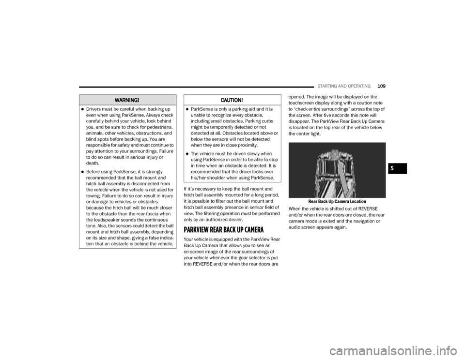
is located on the top rear of the vehicle below
the center light.
Rear Back Up Camera Location
When the vehicle is shifted out of REVERSE
and/or when the rear doors are closed, the rear
camera mode is exited and the navigation or
audio screen appears again.
WARNING!
Drivers must be careful when backing up
even when using ParkSense. Always check
carefully behind your vehicle, look behind
you, and be sure to check for pedestrians,
animals, other vehicles, obstructions, and
blind spots before backing up. You are
responsible for safety and must continue to
pay attention to your surroundings. Failure
to do so can result in serious injury or
death.
Before using ParkSense, it is strongly
recommended that the ball mount and
hitch ball assembly is disconnected from
the vehicle when the vehicle is not used for
towing. Failure to do so can result in injury
or damage to vehicles or obstacles
because the hitch ball will be much closer
to the obstacle than the rear fascia when
the loudspeaker sounds the continuous
tone. Also, the sensors could detect the ball
mount and hitch ball assembly, depending
on its size and shape, giving a false indica -
tion that an obstacle is behind the vehicle.
CAUTION!
ParkSense is only a parking aid and it is
unable to recognize every obstacle,
including small obstacles. Parking curbs
might be temporarily detected or not
detected at all. Obstacles located above or
below the sensors will not be detected
when they are in close proximity.
The vehicle must be driven slowly when
using ParkSense in order to be able to stop
in time when an obstacle is detected. It is
recommended that the driver looks over
his/her shoulder when using ParkSense.
5
20_VF_OM_EN_US_t.book Page 109
Page 112 of 264

110STARTING AND OPERATING
When displayed, static grid lines will illustrate the width of the vehicle and will show separate zones that will help indicate the distance to the rear of
the vehicle. The following table shows the approximate distances for each zone:
NOTE:
If snow, ice, mud, or any foreign substance
builds up on the camera lens, clean the lens,
rinse with water, and dry with a soft cloth. Do
not cover the lens.
Zone
Distance To The Rear Of The Vehicle
Red 0 - 1 ft (0 - 30 cm)
Yellow 1 ft - 3 ft (30 cm - 1 m)
Green 3 ft or greater (1 m or greater)
WARNING!
Drivers must be careful when backing up
even when using the Rear Back Up Camera.
Always check carefully behind your vehicle,
and be sure to check for pedestrians,
animals, other vehicles, obstructions, or blind
spots before backing up. You are responsible
for the safety of your surroundings and must
continue to pay attention while backing up.
Failure to do so can result in serious injury or
death.
CAUTION!
To avoid vehicle damage, ParkView should
only be used as a parking aid. The ParkView
camera is unable to view every obstacle or
object in your drive path.
To avoid vehicle damage, the vehicle must
be driven slowly when using ParkView to be
able to stop in time when an obstacle is
seen. It is recommended that the driver
look frequently over his/her shoulder when
using ParkView.
20_VF_OM_EN_US_t.book Page 110
Page 119 of 264

STARTING AND OPERATING117
Towing Requirements — Tires
Do not attempt to tow a trailer while using a
compact spare tire.
Do not drive more than 50 mph (80 km/h) when towing while using a full size spare tire.
Proper tire inflation pressures are essential
to the safe and satisfactory operation of your
vehicle. Refer to “Tires” in “Servicing And
Maintenance” for proper tire inflation proce -
dures.
Check the trailer tires for proper tire inflation
pressures before trailer usage.
Check for signs of tire wear or visible tire
damage before towing a trailer. Refer to
“Tires” in “Servicing And Maintenance” for
the proper inspection procedure.
When replacing tires, refer to “Tires” in
“Servicing And Maintenance” for the proper
tire replacement procedures. Replacing tires
with a higher load carrying capacity will not
increase the vehicle's GVWR and GAWR
limits.
Towing Requirements — Trailer Brakes
Do not interconnect the hydraulic brake
system or vacuum system of your vehicle
with that of the trailer. This could cause inad -
equate braking and possible personal injury.
An electronically actuated trailer brake
controller is required when towing a trailer
with electronically actuated brakes. When
towing a trailer equipped with a hydraulic
surge actuated brake system, an electronic
brake controller is not required.
Trailer brakes are recommended for trailers
over 1,000 lbs (453 kg) and may be required
for any trailer, for example trailers in excess
of 2,000 lbs (907 kg). Trailer brake require -
ments vary by local law, consult local legal
requirements where the trailer is to be towed
for trailer brake requirements.
WARNING!
Do not connect trailer brakes to your
vehicle's hydraulic brake lines. It can over -
load your brake system and cause it to fail.
You might not have brakes when you need
them and could have an accident.
Towing any trailer will increase your stop -
ping distance. When towing, you should
allow for additional space between your
vehicle and the vehicle in front of you.
Failure to do so could result in an accident.
CAUTION!
If the trailer weighs more than 1,000 lbs
(453 kg) loaded, it should have its own
brakes and they should be of adequate
capacity. Failure to do this could lead to
accelerated brake lining wear, higher brake
pedal effort, and longer stopping distances.
5
20_VF_OM_EN_US_t.book Page 117
Page 120 of 264

118STARTING AND OPERATING
Towing Requirements — Trailer Lights And Wiring
Whenever you pull a trailer, regardless of the
trailer size, stoplights and turn signals on the
trailer are required for motoring safety.
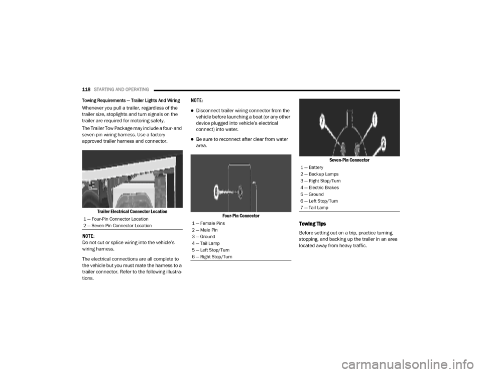
The Trailer Tow Package may include a four- and
seven-pin wiring harness. Use a factory
approved trailer harness and connector.
Trailer Electrical Connector Location
NOTE:
Do not cut or splice wiring into the vehicle’s
wiring harness.
The electrical connections are all complete to
the vehicle but you must mate the harness to a
trailer connector. Refer to the following illustra -
tions. NOTE:Disconnect trailer wiring connector from the
vehicle before launching a boat (or any other
device plugged into vehicle’s electrical
connect) into water.
Be sure to reconnect after clear from water
area.
Four-Pin Connector Seven-Pin Connector
Towing Tips
Before setting out on a trip, practice turning,
stopping, and backing up the trailer in an area
located away from heavy traffic.
1 — Four-Pin Connector Location
2 — Seven-Pin Connector Location1 — Female Pins
2 — Male Pin
3 — Ground
4 — Tail Lamp
5 — Left Stop/Turn
6 — Right Stop/Turn
1 — Battery
2 — Backup Lamps
3 — Right Stop/Turn
4 — Electric Brakes
5 — Ground
6 — Left Stop/Turn
7 — Tail Lamp
20_VF_OM_EN_US_t.book Page 118
Page 121 of 264

STARTING AND OPERATING119
Automatic Transmission
The DRIVE range can be selected when towing.
The transmission controls include a drive
strategy to avoid frequent shifting when towing.
However, if frequent shifting does occur while in
DRIVE, select TOW/HAUL mode or select a lower
gear range (using the Electronic Range Select
(ERS) shift control).
NOTE:
Using TOW/HAUL mode or selecting a lower
gear range (using the ERS shift control) while
operating the vehicle under heavy loading
conditions will improve performance and
extend transmission life by reducing excessive
shifting and heat build up. This action will also
provide better engine braking.
When towing a loaded trailer up steep grades at
low speeds, holding your vehicle in first gear
(using the ERS shift control) can help to avoid
transmission overheating.
Tow/Haul Mode
To reduce potential for automatic transmission
overheating, activate TOW/HAUL mode when
driving in hilly areas, or select a lower gear
range (using the Electronic Range Select (ERS)
shift control) on more severe grades.
Speed Control — If Equipped
Do not use on hilly terrain or with heavy
loads.
When using the speed control, if you experi -
ence speed drops greater than 10 mph
(16 km/h), disengage until you can get back
to cruising speed.
Use speed control in flat terrain and with light
loads to maximize fuel efficiency.
Cooling System
To reduce potential for engine and transmission
overheating, take the following actions:
City Driving
In city traffic — while stopped, place the trans -
mission in NEUTRAL, but do not increase engine
idle speed.
Highway Driving
Reduce speed.
Temporarily turn off air conditioning.
5
20_VF_OM_EN_US_t.book Page 119
Page 123 of 264

STARTING AND OPERATING121
DRIVING TIPS
Driving On Slippery Surfaces
Acceleration
Rapid acceleration on snow covered, wet, or
other slippery surfaces may cause the driving
wheels to pull erratically to the right or left. This
phenomenon occurs when there is a difference
in the surface traction under the front (driving)
wheels.
Traction
When driving on wet or slushy roads, it is
possible for a wedge of water to build up
between the tire and road surface. This is hydro -
planing and may cause partial or complete loss
of vehicle control and stopping ability. To
reduce this possibility, the following precau -
tions should be observed:
Slow down during rainstorms or when the
roads are slushy.
Slow down if the road has standing water or
puddles.
Replace the tires when tread wear indicators
first become visible.
Keep tires properly inflated.
Maintain sufficient distance between your
vehicle and the vehicle in front of you to avoid
a collision in a sudden stop.
Driving Through Water
Driving through water more than a few inches/
centimeters deep will require extra caution to
ensure safety and prevent damage to your
vehicle.
Flowing/Rising Water
WARNING!
Rapid acceleration on slippery surfaces is
dangerous. Unequal traction can cause
sudden pulling of the front wheels. You could
lose control of the vehicle and possibly have a
collision. Accelerate slowly and carefully
whenever there is likely to be poor traction
(ice, snow, wet, mud, loose sand, etc.).
WARNING!
Do not drive on or across a road or path
where water is flowing and/or rising (as in
storm run-off). Flowing water can wear away
the road or path's surface and cause your
vehicle to sink into deeper water.
Furthermore, flowing and/or rising water can
carry your vehicle away swiftly. Failure to
follow this warning may result in injuries that
are serious or fatal to you, your passengers,
and others around you.
5
20_VF_OM_EN_US_t.book Page 121
Page 124 of 264

122STARTING AND OPERATING
(Continued)
Shallow Standing Water
Although your vehicle is capable of driving
through shallow standing water, consider the
following Cautions and Warnings before doing
so.
WARNING!
Driving through standing water limits your
vehicle’s traction capabilities. Do not
exceed 5 mph (8 km/h) when driving
through standing water.
Driving through standing water limits your
vehicle’s braking capabilities, which
increases stopping distances. Therefore,
after driving through standing water, drive
slowly and lightly press on the brake pedal
several times to dry the brakes.
Failure to follow these warnings may result
in injuries that are serious or fatal to you,
your passengers, and others around you.
CAUTION!
Always check the depth of the standing
water before driving through it. Never drive
through standing water that is deeper than
the bottom of the tire rims mounted on the
vehicle.
Determine the condition of the road or the
path that is under water and if there are any
obstacles in the way before driving through
the standing water.
Do not exceed 5 mph (8 km/h) when
driving through standing water. This will
minimize wave effects.
Driving through standing water may cause
damage to your vehicle’s drivetrain compo -
nents. Always inspect your vehicle’s fluids
(i.e., engine oil, transmission, axle, etc.) for
signs of contamination (i.e., fluid that is
milky or foamy in appearance) after driving
through standing water. Do not continue to
operate the vehicle if any fluid appears
contaminated, as this may result in further
damage. Such damage is not covered by
the New Vehicle Limited Warranty.
Getting water inside your vehicle’s engine
can cause it to lock up and stall out, and
cause serious internal damage to the
engine. Such damage is not covered by the
New Vehicle Limited Warranty.
CAUTION!
(Continued)
20_VF_OM_EN_US_t.book Page 122
Page 144 of 264

142IN CASE OF EMERGENCY
Sealing A Tire With Tire Service Kit
(A) Whenever You Stop To Use Tire Service Kit:
1. Pull over to a safe location and turn on the
vehicle’s Hazard Warning flashers.
2. Verify that the valve stem (on the wheel with the deflated tire) is in a position that is near
to the ground. This will allow the Tire Service
Kit Hoses (3) and (5) to reach the valve
stem and keep the Tire Service Kit flat on
the ground. This will provide the best posi -
tioning of the kit when injecting the sealant
into the deflated tire and running the air
pump. Move the vehicle as necessary to
place the valve stem in this position before
proceeding.
3. Place the transmission in PARK (P) (auto transmission) or in Gear (manual transmis -
sion) and place the ignition in the OFF posi -
tion.
4. Apply the parking brake.
(B) Setting Up To Use Tire Service Kit:
1. Push in the Mode Select Knob (2) and turn to the Sealant Mode position. 2. Uncoil the Sealant Hose (3) and then
remove the cap from the fitting at the end of
the hose.
3. Place the Tire Service Kit flat on the ground next to the deflated tire.
4. Remove the cap from the valve stem and then screw the fitting at the end of the
Sealant Hose (3) onto the valve stem.
5. Uncoil the Power Plug (7) and insert the plug into the vehicle’s 12 Volt power outlet.
NOTE:
Do not remove foreign objects (e.g., screws or
nails) from the tire.
(C) Injecting Tire Service Kit Sealant Into The
Deflated Tire:
Always start the engine before turning ON the
Tire Service Kit.
NOTE:
Manual transmission vehicles must have the
parking brake engaged and the gear selector in
NEUTRAL.
After pushing the Power Button (1), the
sealant (white fluid) will flow from the Sealant
Bottle (4) through the Sealant Hose (3) and
into the tire. NOTE:
Sealant may leak out through the puncture in
the tire.
If the sealant (white fluid) does not flow within 0
– 10 seconds through the Sealant Hose (3):
1. Push the Power Button (1) to turn Off the
Tire Service Kit. Disconnect the Sealant
Hose (3) from the valve stem. Make sure
the valve stem is free of debris. Reconnect
the Sealant Hose (3) to the valve stem.
Check that the Mode Select Knob (2) is in
the Sealant Mode position and not Air
Mode. Push the Power Button (1) to turn On
the Tire Service Kit.
2. Connect the Power Plug (7) to a different 12 Volt power outlet in your vehicle or another
vehicle, if available. Make sure the engine is
running before turning ON the Tire Service
Kit.
3. The Sealant Bottle (4) may be empty due to previous use. Call for assistance.
NOTE:
If the Mode Select Knob (2) is on Air Mode and
the pump is operating, air will dispense from the
Air Pump Hose (5) only, not the Sealant Hose
(3).
20_VF_OM_EN_US_t.book Page 142