Flasher Ram ProMaster 2020 Owner's Manual
[x] Cancel search | Manufacturer: RAM, Model Year: 2020, Model line: ProMaster, Model: Ram ProMaster 2020Pages: 264, PDF Size: 10.11 MB
Page 6 of 264

4
VEHICLE LOADING ................................................112
Vehicle Certification Label ............................... 112
Gross Vehicle Weight Rating (GVWR) .............. 112
Gross Axle Weight Rating (GAWR) .................. 112
Tire Size .............................................................112
Rim Size ............................................................ 112
Inflation Pressure ............................................. 112
Curb Weight ...................................................... 112
Overloading ....................................................... 112
Loading .............................................................113
TRAILER TOWING ..................................................113
Common Towing Definitions ............................113
Trailer Hitch Classification ............................... 114
Trailer Towing Weights
(Maximum Trailer Weight Ratings) ................. 115 Trailer And Tongue Weight ..............................115Towing Requirements ..................................... 116
Towing Tips ...................................................... 118
RECREATIONAL TOWING
(BEHIND MOTORHOME, ETC.) ............................120
Towing This Vehicle Behind Another Vehicle .. 120
Recreational Towing ......................................... 120
DRIVING TIPS.........................................................121
Driving On Slippery Surfaces ..........................121
Driving Through Water ....................................121
IN CASE OF EMERGENCY
HAZARD WARNING FLASHERS ..........................123 BULB REPLACEMENT ........................................... 123
Replacement Bulbs .......................................... 123
Replacing Exterior Bulbs .................................. 125
Replacing Interior Bulbs .................................. 127
FUSES..................................................................... 128
Underhood Fuses ............................................. 128
Interior Fuses.................................................... 131
Right Central Pillar Fuses ................................ 132
JACKING AND TIRE CHANGING .......................... 133
Jack Location .................................................... 133
Spare Tire Removal .......................................... 134
Preparations For Jacking ................................. 135
Jacking Instructions ......................................... 136Wheel Covers .................................................... 139
TIRE SERVICE KIT — IF EQUIPPED ...................... 139
Tire Service Kit Storage ................................... 139
Tire Service Kit Components And Operation .. 140Tire Service Kit Usage Precautions ................. 140
Sealing A Tire With Tire Service Kit ................. 142
JUMP STARTING ................................................... 145
Preparations For Jump Start ........................... 145
Jump Starting Procedure ................................. 146
Battery Location ............................................... 147
IF YOUR ENGINE OVERHEATS ............................ 147
GEAR SELECTOR OVERRIDE .............................. 148FREEING A STUCK VEHICLE ............................... 149
TOWING A DISABLED VEHICLE........................... 149
Automatic Transmission .................................. 150
ENHANCED ACCIDENT RESPONSE SYSTEM
(EARS) ....................................................................151
EVENT DATA RECORDER (EDR) .......................... 151
SERVICING AND MAINTENANCE
SCHEDULED SERVICING .....................................152
Maintenance Plan ............................................ 152
Heavy Duty Use Of The Vehicle ....................... 155
ENGINE COMPARTMENT...................................... 156
3.6L Engine ..................................................... 156
Checking Oil Level — Gas Engine ................... 157
Adding Washer Fluid ........................................ 157Maintenance-Free Battery .............................. 157
Pressure Washing ............................................ 158
DEALER SERVICE ................................................. 158
Engine Oil ......................................................... 158Engine Oil Filter ................................................ 159
Engine Air Cleaner Filter ................................. 159
Air Conditioner Maintenance ......................... 160
Body Lubrication .............................................. 161
Windshield Wiper Blades ................................ 162
Exhaust System ............................................... 162
Cooling System................................................. 163
Brake System .................................................. 166
Automatic Transmission
(3.6L Gasoline Engine Only) ............................ 167
RAISING THE VEHICLE..........................................168
20_VF_OM_EN_US_t.book Page 4
Page 60 of 264
58SAFETY
(Continued)
ESC Operating Modes
The “ESC OFF” switch is located in the
center switch bank, next to the hazard
flasher switch.
ESC On
This mode is the normal operating mode for ESC
equipped vehicles. Whenever the vehicle is
started, the ESC system will be in this mode.
This mode should be used for most driving situ -
ations. ESC should only be turned off for
specific reasons as noted below.
ESC Partial Off
This mode is entered by momentarily pushing
the “ESC OFF” switch.
When in the “Partial Off” mode, the TCS portion
of ESC, except for the “limited slip” feature
described in the TCS section, has been disabled
and the “ESC OFF Indicator Light” will be illumi-
nated. When in the “Partial Off” mode, ESC will
operate without engine torque management.
This mode is intended to be used if the vehicle is
in deep snow, sand or gravel conditions and
more wheel spin than ESC would normally allow
is required to gain traction. To turn ESC on again,
momentarily push the “ESC OFF” switch. This will
restore the normal “ESC On” mode of operation.
WARNING!
Electronic Stability Control (ESC) cannot
prevent the natural laws of physics from
acting on the vehicle, nor can it increase
the traction afforded by prevailing road
conditions. ESC cannot prevent acci -
dents, including those resulting from
excessive speed in turns, driving on very
slippery surfaces, or hydroplaning. ESC
also cannot prevent accidents resulting
from loss of vehicle control due to inap -
propriate driver input for the conditions.
Only a safe, attentive, and skillful driver
can prevent accidents. The capabilities of
an ESC equipped vehicle must never be
exploited in a reckless or dangerous
manner which could jeopardize the user’s
safety or the safety of others.Vehicle modifications, or failure to properly
maintain your vehicle, may change the
handling characteristics of your vehicle,
and may negatively affect the performance
of the ESC system. Changes to the steering
system, suspension, braking system, tire
type and size or wheel size may adversely
affect ESC performance. Improperly
inflated and unevenly worn tires may also
degrade ESC performance. Any vehicle
modification or poor vehicle maintenance
that reduces the effectiveness of the ESC
system can increase the risk of loss of
vehicle control, vehicle rollover, personal
injury and death.
WARNING!
(Continued)
20_VF_OM_EN_US_t.book Page 58
Page 125 of 264
123
IN CASE OF EMERGENCY
HAZARD WARNING FLASHERS
The Hazard Warning flashers switch is located
on the instrument panel below the climate
controls.Push the switch to turn on the Hazard
Warning flashers. When the switch is
activated, all directional turn signals will flash on and off to warn oncoming traffic of
an emergency. Push the switch a second time to
turn off the Hazard Warning flashers.
This is an emergency warning system and it
should not be used when the vehicle is in
motion. Use it when your vehicle is disabled and
it is creating a safety hazard for other motorists.
When you must leave the vehicle to seek assis
-
tance, the Hazard Warning flashers will
continue to operate even though the ignition is
placed in the OFF position.
NOTE:
With extended use, the Hazard Warning
flashers may wear down your battery.
BULB REPLACEMENT
Replacement Bulbs
Interior Bulbs
Bulb Name Bulb Number
Dome Lamp C5W
Courtesy Lamp FF500
Cargo Lamp C5W
Exterior Bulbs
Bulb Name Bulb Number
Front Low and High Beam Headlamp H7SLL
Front Park/Turn Signal Lamps 7444NA
6
20_VF_OM_EN_US_t.book Page 123
Page 137 of 264
IN CASE OF EMERGENCY135
NOTE:
The winch mechanism is designed for use with
the winch extension tube only. Use of an air
wrench or other power tools is not recom-
mended and can damage the winch.
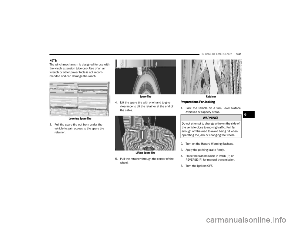
Lowering Spare Tire
3. Pull the spare tire out from under the vehicle to gain access to the spare tire
retainer. Spare Tire
4. Lift the spare tire with one hand to give clearance to tilt the retainer at the end of
the cable.
Lifting Spare Tire
5. Pull the retainer through the center of the wheel. Retainer
Preparations For Jacking
1. Park the vehicle on a firm, level surface.
Avoid ice or slippery areas.
2. Turn on the Hazard Warning flashers.
3. Apply the parking brake firmly.
4. Place the transmission in PARK (P) or REVERSE (R) for manual transmission.
5. Turn the ignition OFF.
WARNING!
Do not attempt to change a tire on the side of
the vehicle close to moving traffic. Pull far
enough off the road to avoid being hit when
operating the jack or changing the wheel.
6
20_VF_OM_EN_US_t.book Page 135
Page 138 of 264
136IN CASE OF EMERGENCY
(Continued)
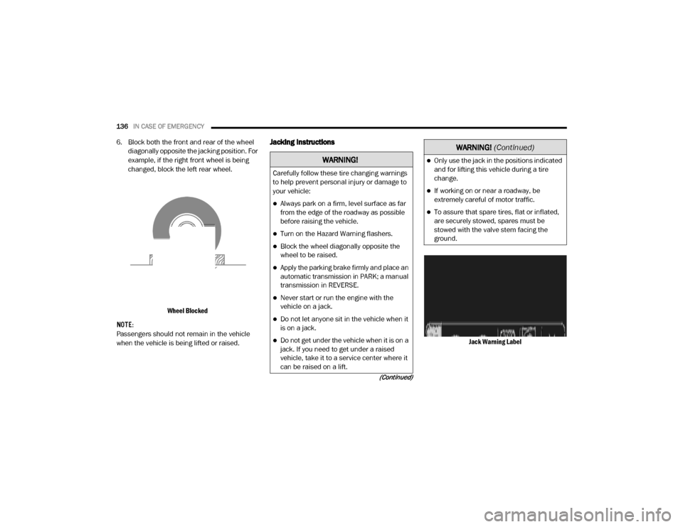
6. Block both the front and rear of the wheel
diagonally opposite the jacking position. For
example, if the right front wheel is being
changed, block the left rear wheel.
Wheel Blocked
NOTE:
Passengers should not remain in the vehicle
when the vehicle is being lifted or raised.Jacking Instructions
Jack Warning Label
WARNING!
Carefully follow these tire changing warnings
to help prevent personal injury or damage to
your vehicle:
Always park on a firm, level surface as far
from the edge of the roadway as possible
before raising the vehicle.
Turn on the Hazard Warning flashers.
Block the wheel diagonally opposite the
wheel to be raised.
Apply the parking brake firmly and place an
automatic transmission in PARK; a manual
transmission in REVERSE.
Never start or run the engine with the
vehicle on a jack.
Do not let anyone sit in the vehicle when it
is on a jack.
Do not get under the vehicle when it is on a
jack. If you need to get under a raised
vehicle, take it to a service center where it
can be raised on a lift.
Only use the jack in the positions indicated
and for lifting this vehicle during a tire
change.
If working on or near a roadway, be
extremely careful of motor traffic.
To assure that spare tires, flat or inflated,
are securely stowed, spares must be
stowed with the valve stem facing the
ground.
WARNING!
(Continued)
20_VF_OM_EN_US_t.book Page 136
Page 144 of 264
142IN CASE OF EMERGENCY
Sealing A Tire With Tire Service Kit
(A) Whenever You Stop To Use Tire Service Kit:
1. Pull over to a safe location and turn on the
vehicle’s Hazard Warning flashers.
2. Verify that the valve stem (on the wheel with the deflated tire) is in a position that is near
to the ground. This will allow the Tire Service
Kit Hoses (3) and (5) to reach the valve
stem and keep the Tire Service Kit flat on
the ground. This will provide the best posi -
tioning of the kit when injecting the sealant
into the deflated tire and running the air
pump. Move the vehicle as necessary to
place the valve stem in this position before
proceeding.
3. Place the transmission in PARK (P) (auto transmission) or in Gear (manual transmis -
sion) and place the ignition in the OFF posi -
tion.
4. Apply the parking brake.
(B) Setting Up To Use Tire Service Kit:
1. Push in the Mode Select Knob (2) and turn to the Sealant Mode position. 2. Uncoil the Sealant Hose (3) and then
remove the cap from the fitting at the end of
the hose.
3. Place the Tire Service Kit flat on the ground next to the deflated tire.
4. Remove the cap from the valve stem and then screw the fitting at the end of the
Sealant Hose (3) onto the valve stem.
5. Uncoil the Power Plug (7) and insert the plug into the vehicle’s 12 Volt power outlet.
NOTE:
Do not remove foreign objects (e.g., screws or
nails) from the tire.
(C) Injecting Tire Service Kit Sealant Into The
Deflated Tire:
Always start the engine before turning ON the
Tire Service Kit.
NOTE:
Manual transmission vehicles must have the
parking brake engaged and the gear selector in
NEUTRAL.
After pushing the Power Button (1), the
sealant (white fluid) will flow from the Sealant
Bottle (4) through the Sealant Hose (3) and
into the tire. NOTE:
Sealant may leak out through the puncture in
the tire.
If the sealant (white fluid) does not flow within 0
– 10 seconds through the Sealant Hose (3):
1. Push the Power Button (1) to turn Off the
Tire Service Kit. Disconnect the Sealant
Hose (3) from the valve stem. Make sure
the valve stem is free of debris. Reconnect
the Sealant Hose (3) to the valve stem.
Check that the Mode Select Knob (2) is in
the Sealant Mode position and not Air
Mode. Push the Power Button (1) to turn On
the Tire Service Kit.
2. Connect the Power Plug (7) to a different 12 Volt power outlet in your vehicle or another
vehicle, if available. Make sure the engine is
running before turning ON the Tire Service
Kit.
3. The Sealant Bottle (4) may be empty due to previous use. Call for assistance.
NOTE:
If the Mode Select Knob (2) is on Air Mode and
the pump is operating, air will dispense from the
Air Pump Hose (5) only, not the Sealant Hose
(3).
20_VF_OM_EN_US_t.book Page 142
Page 254 of 264

252
Engine
................................................ 156Air Cleaner...................................... 159Block Heater..................................... 93Break-In Recommendations.................. 93Compartment.................................. 156Compartment Identification................ 156Coolant (Antifreeze)................... 163, 195Cooling........................................... 163Exhaust Gas Caution................... 89, 194Fails To Start..................................... 92Flooded, Starting................................ 92Fuel Requirements................... 192, 195Jump Starting.................................. 145Oil......................................... 158, 195Oil Filler Cap.................................... 156Oil Filter......................................... 159Oil Selection............................ 158, 195Oil Synthetic.................................... 159Overheating.................................... 147Starting............................................ 92
Engine Oil Viscosity
................................. 159
Engine Oil Viscosity Chart
.......................... 159
Enhanced Accident Response Feature
........... 151
Entry System, Illuminated
............................ 27
Ethanol
............................................... 193
Exhaust Gas Cautions
........................ 89, 194
Exhaust System
............................... 89, 162
Exterior Lights
................................... 23, 91
F
Filters
Air Cleaner
...................................... 159Air Conditioning.......................... 34, 160Engine Oil............................... 159, 195Engine Oil Disposal........................... 159
Flashers
Hazard Warning................................ 123Turn Signals................................ 53, 91
Flat Tire Changing
........................... 168, 181
Flat Tire Stowage
............................ 168, 181
Flooded Engine Starting
.............................. 92
Fluid Capacities
.....................................195
Fluid Leaks
............................................. 91
Fluid Level Checks
Automatic Transmission..................... 168Brake............................................. 166Cooling System................................ 163Power Steering................................. 103
Fluids And Lubricants
............................... 195
Fog Lights
.............................................. 25
Fold-Flat Seats
........................................ 15
Four-Way Hazard Flasher
........................... 123
Freeing A Stuck Vehicle
............................ 149
Fuel
.................................................. 192Additives........................................ 193Clean Air........................................ 192Ethanol.......................................... 193Filler Cap (Gas Cap).......................... 111Gasoline........................................ 192Materials Added.............................. 193Methanol....................................... 193Octane Rating..........................192, 195Requirements..........................192, 195Tank Capacity................................. 195
Fuses
................................................ 128
G
Gas Cap (Fuel Filler Cap)
.......................... 111
Gasoline, Clean Air
................................. 192
Gasoline, Reformulated
........................... 192
Gear Ranges
.......................................... 97
Gear Selector Override
............................. 148
Glass Cleaning
...................................... 190
Gross Axle Weight Rating
...................112, 113
Gross Vehicle Weight Rating
...............112, 113
Guide
Body Builders...................................... 8
GVWR
................................................ 112
20_VF_OM_EN_US_t.book Page 252
Page 255 of 264

253
H
Hazard
Driving Through Flowing, Rising,
Or Shallow Standing Water
................. 121
Hazard Warning Flashers
.......................... 123
Head Restraints
....................................... 20
Headlights
Cleaning......................................... 187High Beam........................................ 24High Beam/Low Beam Select Switch....... 24Passing............................................ 24Switch.............................................. 23
Heated Mirrors
........................................ 23
Heated Seats
.......................................... 18
Heater, Engine Block
................................. 93
High Beam/Low Beam Select (Dimmer) Switch
... 24
Hill Start Assist
........................................ 60
Hitches
Trailer Towing.................................. 114
Hood Prop
............................................. 36
Hood Release
......................................... 36
I
Ignition
.................................................11Key.............................................. 9, 11Switch.............................................. 11
Ignition Key Removal
.................................11
Illuminated Entry
......................................27
Immobilizer (Sentry Key)
............................. 12
Inside Rearview Mirror
................................21
Instrument Cluster
.............................. 41, 53Display............................................. 43
Instrument Panel Lens Cleaning
................... 189
Interior And Instrument Lights
.......................25
Interior Appearance Care
........................... 188
Interior Lights
..........................................25
Intermittent Wipers (Delay Wipers)
..................28
Introduction
..............................................7
iPod/USB/MP3 Control
............................. 238
J
Jack Location
........................................ 133
Jack Operation
.............................. 133, 168
Jacking And Tire Changing
......................... 133
Jacking And Tire Changing Instructions
...........135
Jump Starting
........................................ 145
K
Key Fob
Programming Additional Key Fobs
.......... 10
Key Fob Battery Service (Remote Keyless Entry)
.. 10
Key Fob Programming (Remote Keyless Entry)
.... 10
Key-In Reminder
...................................... 12
Keys
..................................................... 9Replacement.................................... 12Sentry (Immobilizer)............................ 12
L
Lane Change Assist
.................................. 25
Lap/Shoulder Belts
.................................. 67
Latches
................................................ 91Hood............................................... 36
Lead Free Gasoline
................................ 192
Leaks, Fluid
........................................... 91
Life Of Tires
......................................... 179
Light Bulbs
.....................................91, 123
Lights
.................................................. 91Air Bag................................. 47, 73, 90Brake Assist Warning.......................... 59Brake Warning.................................. 48Bulb Replacement............................ 123Cruise............................................. 53Daytime Running............................... 24Dimmer Switch, Headlight...............23, 2411
20_VF_OM_EN_US_t.book Page 253
Page 256 of 264

254
Electronic Stability Program(ESP) Indicator
................................. 48, 59Exterior...................................... 23, 91Hazard Warning Flasher..................... 123Headlights........................................ 23High Beam........................................ 24Illuminated Entry................................ 27Interior............................................. 25Malfunction Indicator (Check Engine)...... 51Park.......................................... 24, 53Passing............................................ 24Security Alarm................................... 49Service........................................... 123Tire Pressure Monitoring (TPMS)............ 61Traction Control.................................. 59Turn Signals.......................... 23, 53, 91Warning Instrument Cluster Descriptions................... 48, 53
Loading Vehicle
............................. 112, 113Capacities....................................... 113Tires.............................................. 173
Locks
Automatic Door............................ 14, 15
Low Tire Pressure System
............................ 61
Lubrication, Body
................................... 161
Lug Nuts/Bolts
...................................... 191
M
Maintenance Free Battery
.......................... 157
Maintenance Schedule
............................. 152
Malfunction Indicator Light (Check Engine)
.. 51, 55
Manual
Service........................................... 249
Methanol
............................................. 193
Mirrors
.................................................21Electric Remote.................................. 22Exterior Folding.................................. 22Heated............................................. 23Outside............................................21Rearview..........................................21
Modifications/Alterations
Vehicle...............................................8
Monitor, Tire Pressure System
.......................61
Mopar Parts
..........................................248
MP3 Control
......................................... 238
Multi-Function Control Lever
......................... 23
N
New Vehicle Break-In Period
......................... 93
O
Occupant Restraints
................................. 64
Octane Rating, Gasoline (Fuel)
.................... 192
Oil Change Indicator
................................. 44Reset.............................................. 44
Oil Filter, Change
................................... 159
Oil Filter, Selection
................................. 159
Oil Pressure Light
..................................... 49
Oil, Engine
....................................158, 195Capacity........................................ 195Change Interval............................... 158Dipstick......................................... 157Disposal........................................ 159Filter...................................... 159, 195Filter Disposal................................. 159Identification Logo............................ 159Materials Added To.......................... 159Pressure Warning Light....................... 49Recommendation.....................158, 195Synthetic........................................ 159Viscosity................................. 159, 195
Onboard Diagnostic System
......................... 54
Operating Precautions
............................... 54
Operator Manual
Owner's Manual............................ 8, 249
Outside Rearview Mirrors
............................ 21
Overheating, Engine
................................ 147
20_VF_OM_EN_US_t.book Page 254