fuse Ram ProMaster 2020 Owner's Manual
[x] Cancel search | Manufacturer: RAM, Model Year: 2020, Model line: ProMaster, Model: Ram ProMaster 2020Pages: 264, PDF Size: 10.11 MB
Page 6 of 264

4
VEHICLE LOADING ................................................112
Vehicle Certification Label ............................... 112
Gross Vehicle Weight Rating (GVWR) .............. 112
Gross Axle Weight Rating (GAWR) .................. 112
Tire Size .............................................................112
Rim Size ............................................................ 112
Inflation Pressure ............................................. 112
Curb Weight ...................................................... 112
Overloading ....................................................... 112
Loading .............................................................113
TRAILER TOWING ..................................................113
Common Towing Definitions ............................113
Trailer Hitch Classification ............................... 114
Trailer Towing Weights
(Maximum Trailer Weight Ratings) ................. 115 Trailer And Tongue Weight ..............................115Towing Requirements ..................................... 116
Towing Tips ...................................................... 118
RECREATIONAL TOWING
(BEHIND MOTORHOME, ETC.) ............................120
Towing This Vehicle Behind Another Vehicle .. 120
Recreational Towing ......................................... 120
DRIVING TIPS.........................................................121
Driving On Slippery Surfaces ..........................121
Driving Through Water ....................................121
IN CASE OF EMERGENCY
HAZARD WARNING FLASHERS ..........................123 BULB REPLACEMENT ........................................... 123
Replacement Bulbs .......................................... 123
Replacing Exterior Bulbs .................................. 125
Replacing Interior Bulbs .................................. 127
FUSES..................................................................... 128
Underhood Fuses ............................................. 128
Interior Fuses.................................................... 131
Right Central Pillar Fuses ................................ 132
JACKING AND TIRE CHANGING .......................... 133
Jack Location .................................................... 133
Spare Tire Removal .......................................... 134
Preparations For Jacking ................................. 135
Jacking Instructions ......................................... 136Wheel Covers .................................................... 139
TIRE SERVICE KIT — IF EQUIPPED ...................... 139
Tire Service Kit Storage ................................... 139
Tire Service Kit Components And Operation .. 140Tire Service Kit Usage Precautions ................. 140
Sealing A Tire With Tire Service Kit ................. 142
JUMP STARTING ................................................... 145
Preparations For Jump Start ........................... 145
Jump Starting Procedure ................................. 146
Battery Location ............................................... 147
IF YOUR ENGINE OVERHEATS ............................ 147
GEAR SELECTOR OVERRIDE .............................. 148FREEING A STUCK VEHICLE ............................... 149
TOWING A DISABLED VEHICLE........................... 149
Automatic Transmission .................................. 150
ENHANCED ACCIDENT RESPONSE SYSTEM
(EARS) ....................................................................151
EVENT DATA RECORDER (EDR) .......................... 151
SERVICING AND MAINTENANCE
SCHEDULED SERVICING .....................................152
Maintenance Plan ............................................ 152
Heavy Duty Use Of The Vehicle ....................... 155
ENGINE COMPARTMENT...................................... 156
3.6L Engine ..................................................... 156
Checking Oil Level — Gas Engine ................... 157
Adding Washer Fluid ........................................ 157Maintenance-Free Battery .............................. 157
Pressure Washing ............................................ 158
DEALER SERVICE ................................................. 158
Engine Oil ......................................................... 158Engine Oil Filter ................................................ 159
Engine Air Cleaner Filter ................................. 159
Air Conditioner Maintenance ......................... 160
Body Lubrication .............................................. 161
Windshield Wiper Blades ................................ 162
Exhaust System ............................................... 162
Cooling System................................................. 163
Brake System .................................................. 166
Automatic Transmission
(3.6L Gasoline Engine Only) ............................ 167
RAISING THE VEHICLE..........................................168
20_VF_OM_EN_US_t.book Page 4
Page 41 of 264
GETTING TO KNOW YOUR VEHICLE39
Power Outlets
Passenger Compartment Power Outlet
The power outlet is located on the instrument
panel passenger compartment near the cup
holder. It only operates with the ignition key at
MAR (ACC/ON/RUN).
Passenger Compartment Power Outlet Load Compartment Power Outlet — If Equipped
The load compartment power outlet is located
in rear cargo compartment. The outlet can be is
used for powering 12 Volt adaptive accessories
and recharging communications devices.
Load Compartment Power Outlet
NOTE:
Do not connect devices with power higher than
180 W to the socket. Do not damage the socket
by using unsuitable adaptors. Power Outlet Fuses — Under Hood
1 — F14 Fuse 20 Amp Yellow Front Power Outlet
2 — F09 Fuse 15 Amp Blue Rear Power Outlet
WARNING!
To avoid serious injury or death:
Only devices designed for use in this type of
outlet should be inserted into any 12 Volt
outlet.
Do not touch with wet hands.
Close the lid when not in use and while
driving the vehicle.
If this outlet is mishandled, it may cause an
electric shock and failure.
2
20_VF_OM_EN_US_t.book Page 39
Page 42 of 264
40GETTING TO KNOW YOUR VEHICLE
Auxiliary Switches — If Equipped
Your vehicle may be equipped with two auxiliary
switches located on the instrument panel to the
left of the steering column which can be used to
power various electronic devices. Connections
to the switches are found in the right central
pillar fuse panel at the base of the passenger
side B-pillar.
Auxiliary Upfitter Switches Auxiliary Switch 1 is configured to constant
battery feed, while Auxiliary Switch 2 is config
-
ured to ignition feed.
For further information on using the auxiliary
switches, please refer to the Ram Body Builders
Guide by accessing www.rambodybuilder.com
and choosing the appropriate links.CAUTION!
Many accessories that can be plugged in
draw power from the vehicle's battery, even
when not in use (i.e., cellular phones, etc.).
Eventually, if plugged in long enough, the
vehicle's battery will discharge sufficiently
to degrade battery life and/or prevent the
engine from starting.
Accessories that draw higher power (i.e.,
coolers, vacuum cleaners, lights, etc.) will
degrade the battery even more quickly.
Only use these intermittently and with
greater caution.
After the use of high power draw accesso -
ries, or long periods of the vehicle not being
started (with accessories still plugged in),
the vehicle must be driven a sufficient
length of time to allow the generator to
recharge the vehicle's battery.
20_VF_OM_EN_US_t.book Page 40
Page 54 of 264
52GETTING TO KNOW YOUR INSTRUMENT PANEL
Certain conditions, such as a loose or missing
gas cap, poor quality fuel, etc., may illuminate
the light after engine start. The vehicle should
be serviced if the light stays on through several
typical driving styles. In most situations, the
vehicle will drive normally and will not require
towing.
When the engine is running, the MIL may flash
to alert serious conditions that could lead to
immediate loss of power or severe catalytic
converter damage. The vehicle should be
serviced by an authorized dealer as soon as
possible if this occurs.
Anti-Lock Brake (ABS) Warning Light
This light monitors the Anti-Lock
Brake System (ABS). The light will turn
on when the ignition is placed in the
ON/RUN or MAR/ON/RUN position
and may stay on for as long as four seconds.
If the ABS light remains on or turns on while
driving, then the Anti-Lock portion of the brake
system is not functioning and service is
required. However, the conventional brake
system will continue to operate normally if the
brake warning light is not on.
If the ABS light is on, the brake system should
be serviced as soon as possible to restore the
benefits of Anti-Lock Brakes. If the ABS light
does not turn on when the ignition is placed in
the ON/RUN or MAR/ON/RUN position, have
the light inspected by an authorized dealer.
Generic Warning Light
The Generic Warning Light will illumi -
nate if any of the following conditions
occur: Engine Oil Pressure Sensor
Failure, External Light Failure, Fuel
Cut-Off intervention or fail, Parking Sensor
Failure, DST System Failure.
The telltale will remain on fixed in case of swivel
seat failure and on blinking in case of Air Bag
Warning Light Failure. Contact an authorized
dealer immediately for service.
Yellow Indicator Lights
Stop Light Failure Indicator Light
This light will illuminate if one or more
of the stop light bulb fails.
The failure relating to this light could be:
One or more blown bulbs.
A blown protection fuse.
A break in the electrical connection.
WARNING!
A malfunctioning catalytic converter, as
referenced above, can reach higher
temperatures than in normal operating
conditions. This can cause a fire if you drive
slowly or park over flammable substances
such as dry plants, wood, cardboard, etc. This
could result in death or serious injury to the
driver, occupants or others.
CAUTION!
Prolonged driving with the Malfunction
Indicator Light (MIL) on could cause damage
to the vehicle control system. It also could
affect fuel economy and driveability. If the
MIL is flashing, severe catalytic converter
damage and power loss will soon occur.
Immediate service is required.
20_VF_OM_EN_US_t.book Page 52
Page 55 of 264
GETTING TO KNOW YOUR INSTRUMENT PANEL53
External Light Failure Indicator Light — If Equipped
The External Light Failure Indicator
will come on when a failure to one of
the following lights is detected:
Direction Indicators
Backup Lights
Parking Lights
Daytime Running Lights
Clearance Lights
License Plate Lights
The failure relating to these lights could be:
One or more blown bulbs
A blown protection fuse
A break in the electrical connection
TOW/HAUL Indicator Light
This indicator light will illuminate
when TOW/HAUL mode is selected.
Refer to “Trailer To wing ” in “Starting And
Operating” for further information.
Green Indicator Lights
Turn Signal Indicator Light
The turn signal arrows will flash inde -
pendently when left or right turn
signals are selected. Turn signals can
be activated when the multifunction
lever is moved down (left) or up (right).
NOTE:
Check for an inoperative outside light bulb if
either indicator flashes at a rapid rate.
Front Fog Indicator Light — If Equipped
This indicator light will illuminate
when the front fog lights are on.
For further information, refer to “Exte -
rior Lights” in “Getting To Know Your
Vehicle”.
Park/Headlight On Indicator Light
This indicator light will illuminate
when the park lights or headlights are
turned on.
For further information, refer to “Exterior Lights”
in “Getting To Know Your Vehicle”.
Cruise Control Indicator Light — If Equipped
This indicator light will illuminate
when the cruise control is activated.
NOTE:
There will be no change in the indicator light
when the desired speed is set.
Refer to “Speed Control” in “Starting And Oper -
ating” for further information.
Blue Indicator Lights
High Beam Indicator Light
This indicator light will illuminate to
indicate that the high beam head -
lights are on. With the low beams acti -
vated, push the multifunction lever
forward (toward the front of the vehicle) to turn
on the high beams. Pull the multifunction lever
rearward (toward the rear of the vehicle) to turn
off the high beams. If the high beams are off,
pull the lever toward you for a temporary high
beam on, “flash to pass” scenario.
3
20_VF_OM_EN_US_t.book Page 53
Page 130 of 264
128IN CASE OF EMERGENCY
(Continued)
2. Using a suitable tool, flex the housing to lift
the light pod cover away from the unit.
Dome Lamp Light Pod Cover
3. Remove and replace the bulbs as needed.
Dome Lamp Light Bulbs 4. Close the housing cover making sure it
snaps together properly and connect the
lamp.
5. Install overhead console into place making sure to seat the assembly’s forward end
first and then snapping it flush so that the
tension spring is fully seating in the housing.
FUSESUnderhood Fuses
The Front Power Distribution Center is located
on the driver’s side of the engine compartment.
To access the fuses, remove the cover.
Front Power Distribution Center
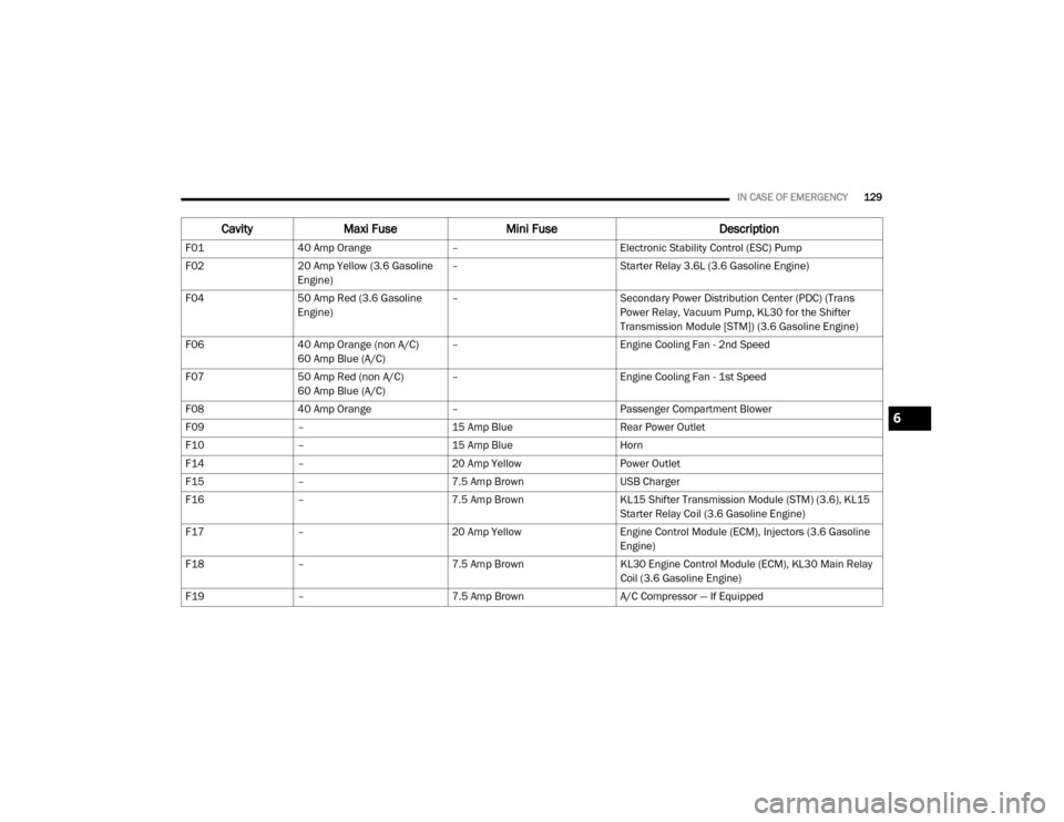
The ID number of the electrical component
corresponding to each fuse can be found on the
back of the cover.WARNING!
When replacing a blown fuse, always use
an appropriate replacement fuse with the
same amp rating as the original fuse. Never
replace a fuse with another fuse of higher
amp rating. Never replace a blown fuse with
metal wires or any other material. Do not
place a fuse inside a circuit breaker cavity
or vice versa. Failure to use proper fuses
may result in serious personal injury, fire
and/or property damage.
Before replacing a fuse, make sure that the
ignition is off and that all the other services
are switched off and/or disengaged.
If the replaced fuse blows again, contact an
authorized dealer.
If a general protection fuse for safety
systems (air bag system, braking system),
power unit systems (engine system, trans -
mission system) or steering system blows,
contact an authorized dealer.
WARNING!
(Continued)
20_VF_OM_EN_US_t.book Page 128
Page 131 of 264
IN CASE OF EMERGENCY129
CavityMaxi Fuse Mini Fuse Description
F0140 Amp Orange – Electronic Stability Control (ESC) Pump
F02 20 Amp Yellow (3.6 Gasoline
Engine) –
Starter Relay 3.6L (3.6 Gasoline Engine)
F04 50 Amp Red (3.6 Gasoline
Engine) –
Secondary Power Distribution Center (PDC) (Trans
Power Relay, Vacuum Pump, KL30 for the Shifter
Transmission Module [STM]) (3.6 Gasoline Engine)
F06 40 Amp Orange (non A/C)
60 Amp Blue (A/C) –
Engine Cooling Fan - 2nd Speed
F07 50 Amp Red (non A/C)
60 Amp Blue (A/C) –
Engine Cooling Fan - 1st Speed
F08 40 Amp Orange – Passenger Compartment Blower
F09 – 15 Amp Blue Rear Power Outlet
F10 – 15 Amp Blue Horn
F14 – 20 Amp Yellow Power Outlet
F15 – 7.5 Amp Brown USB Charger
F16 – 7.5 Amp Brown KL15 Shifter Transmission Module (STM) (3.6), KL15
Starter Relay Coil (3.6 Gasoline Engine)
F17 – 20 Amp Yellow Engine Control Module (ECM), Injectors (3.6 Gasoline
Engine)
F18 – 7.5 Amp Brown KL30 Engine Control Module (ECM), KL30 Main Relay
Coil (3.6 Gasoline Engine)
F19 – 7.5 Amp Brown A/C Compressor — If Equipped
6
20_VF_OM_EN_US_t.book Page 129
Page 132 of 264
130IN CASE OF EMERGENCY
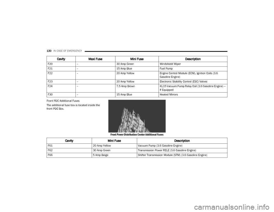
Front PDC Additional Fuses
The additional fuse box is located inside the
front PDC Box.
Front Power Distribution Center Additional Fuses
F20
– 30 Amp Green Windshield Wiper
F21 – 15 Amp Blue Fuel Pump
F22 – 20 Amp Yellow Engine Control Module (ECM), Ignition Coils (3.6
Gasoline Engine)
F23 – 20 Amp Yellow Electronic Stability Control (ESC) Valves
F24 – 7.5 Amp Brown KL15 Vacuum Pump Relay Coil (3.6 Gasoline Engine) —
If Equipped
F30 – 15 Amp Blue Heated Mirrors
CavityMaxi Fuse Mini Fuse Description
CavityMini Fuse Description
F6120 Amp YellowVacuum Pump (3.6 Gasoline Engine)
F62 30 Amp GreenTransmission Power RELE (3.6 Gasoline Engine)
F66 5 Amp BeigeShifter Transmission Module (STM) (3.6 Gasoline Engine)
20_VF_OM_EN_US_t.book Page 130
Page 133 of 264
IN CASE OF EMERGENCY131
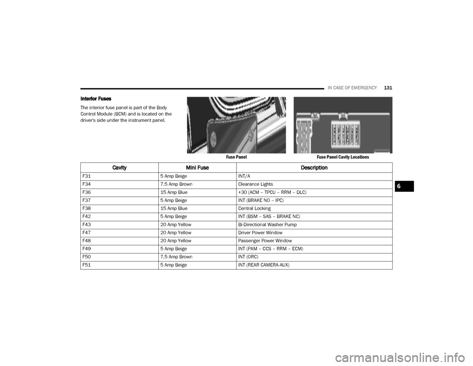
Interior Fuses
The interior fuse panel is part of the Body
Control Module (BCM) and is located on the
driver's side under the instrument panel.
Fuse PanelFuse Panel Cavity Locations
CavityMini Fuse Description
F315 Amp BeigeINT/A
F34 7.5 Amp BrownClearance Lights
F36 15 Amp Blue+30 (ACM – TPCU – RRM – DLC)
F37 5 Amp BeigeINT (BRAKE NO – IPC)
F38 15 Amp BlueCentral Locking
F42 5 Amp BeigeINT (BSM – SAS – BRAKE NC)
F43 20 Amp YellowBi-Directional Washer Pump
F47 20 Amp YellowDriver Power Window
F48 20 Amp YellowPassenger Power Window
F49 5 Amp BeigeINT (PAM – CCS – RRM – ECM)
F50 7.5 Amp BrownINT (ORC)
F51 5 Amp BeigeINT (REAR CAMERA-AUX)
6
20_VF_OM_EN_US_t.book Page 131
Page 134 of 264
132IN CASE OF EMERGENCY
Right Central Pillar Fuses
The right central pillar fuse panel is located on
the interior side at the base of the passenger
side B pillar.
Fuse Panel LocationFuse Panel
F53
5 Amp Beige+30 (IPC) + FTM
F92 7.5 Amp BrownLeft Fog Lamp
F93 7.5 Amp BrownRight Fog Lamp
CavityMini Fuse Description
CavityMini Fuse Description
F817.5 Amp BrownSeat Heater
F83 20 Amp Yellow
Rear Left Windows Heater
F84 20 Amp YellowRear Right Windows Heater
F86 20 Amp YellowAuxiliary Switch (From Battery) — If Equipped
F87 20 Amp YellowAuxiliary Switch (From Ignition) — If Equipped
20_VF_OM_EN_US_t.book Page 132