warning lights Ram ProMaster 2020 Owner's Manual
[x] Cancel search | Manufacturer: RAM, Model Year: 2020, Model line: ProMaster, Model: Ram ProMaster 2020Pages: 264, PDF Size: 10.11 MB
Page 4 of 264

2
INTRODUCTION
INTRODUCTION ......................................................... 7
HOW TO USE THIS MANUAL ................................... 8
Essential Information ........................................... 8
Symbols ................................................................. 8
WARNINGS AND CAUTIONS ................................... 8
VAN CONVERSIONS/CAMPERS .............................. 8
VEHICLE MODIFICATIONS/ALTERATIONS ............. 8
GETTING TO KNOW YOUR VEHICLE
KEYS .......................................................................... 9
Key Fob ................................................................. 9
IGNITION SWITCH ................................................... 11
Mechanical Ignition Switch ................................ 11
Key-In-Ignition Reminder ................................... 12
SENTRY KEY............................................................. 12
Replacement Keys ............................................ 12
General Information ........................................... 12
VEHICLE SECURITY ALARM — IF EQUIPPED ....... 13
To Arm The System ............................................. 13
To Disarm The System ....................................... 13
Rearming Of The System ................................... 14
Security System Manual Override ..................... 14
DOORS ..................................................................... 14
Power Door Locks .............................................. 14
Auto Unlock Doors .............................................. 15
Automatic Door Locks ........................................ 15
SEATS .......................................................................15
Manual Adjustments .......................................... 15
Heated Seats — If Equipped .............................. 18
Fold Down Tray — If Equipped ........................... 19
Adjustable Armrests — If Equipped ................... 19
HEAD RESTRAINTS ................................................20
Front Head Restraint Adjustment ..................... 20
Front Head Restraint Removal .......................... 20
STEERING WHEEL ...................................................21
Telescoping Steering Column ............................ 21
MIRRORS .................................................................21
Inside Day/Night Mirror — If Equipped ............ 21
Outside Mirrors .................................................. 21
Power Mirrors — If Equipped ............................. 22
Power Folding Mirrors — If Equipped ................ 22
Heated Mirrors — If Equipped............................ 23
EXTERIOR LIGHTS ...................................................23
Multifunction Lever ........................................... 23
Headlights .......................................................... 23
Daytime Running Lights (DRLs) —
If Equipped ......................................................... 24 High Beam/Low Beam Select Switch .............. 24
Flash-To-Pass ..................................................... 24
Parking Lights .................................................... 24
Follow Me Home/Headlight Delay .................... 24
Fog Lights — If Equipped ................................... 25
Turn Signals ........................................................ 25
Lane Change Assist............................................ 25
Battery Saver ...................................................... 25
INTERIOR LIGHTS ................................................... 25
Courtesy Lights....................................................25
Illuminated Entry .................................................27
WIPERS AND WASHERS ........................................ 27
Front Wiper Operation .......................................27
CLIMATE CONTROLS .............................................. 28
Manual Climate Control Overview......................28
Climate Control Functions ..................................33
Operating Tips .....................................................33
WINDOWS ............................................................... 35
Power Windows ..................................................35
Window Bar Grates — If Equipped .....................36
Wind Buffeting ....................................................36
HOOD ........................................................................ 36
Opening ...............................................................36
Closing .................................................................37
CARGO AREA FEATURES ....................................... 37
INTERNAL EQUIPMENT .......................................... 37
Storage ................................................................37
Cupholders ..........................................................38
Power Outlets ......................................................39
Auxiliary Switches — If Equipped ........................40
20_VF_OM_EN_US_t.book Page 2
Page 5 of 264

3
GETTING TO KNOW YOUR INSTRUMENT
PANEL
INSTRUMENT CLUSTER .......................................... 41
Instrument Cluster Descriptions........................ 42
INSTRUMENT CLUSTER DISPLAY ......................... 43
Location And Controls ........................................ 43
Change Engine Oil .............................................. 44
Display Setup Menu ........................................... 44
Values Displayed ................................................ 45
Personal Settings (Customer-Programmable
Features) ............................................................. 46
TRIP COMPUTER ..................................................... 46
Trip Button .......................................................... 46
Trip Functions ..................................................... 46
WARNING LIGHTS AND MESSAGES ..................... 47
Red Warning Lights ............................................ 47
Yellow Warning Lights ........................................ 50
Yellow Indicator Lights ....................................... 52
Green Indicator Lights ........................................ 53
Blue Indicator Lights .......................................... 53
ONBOARD DIAGNOSTIC SYSTEM — OBD II ........ 54
Onboard Diagnostic System (OBD II)
Cybersecurity ...................................................... 54
EMISSIONS INSPECTION AND MAINTENANCE
PROGRAMS ............................................................. 55
SAFETY
SAFETY FEATURES ..................................................56
Four-Wheel Anti-Lock Brake System (ABS) ....... 56
Electronic Brake Control (EBC) System ........... 57
AUXILIARY DRIVING SYSTEMS ..............................61
Tire Pressure Monitoring System (TPMS) ......... 61
OCCUPANT RESTRAINT SYSTEMS .......................64
Occupant Restraint Systems Features ............ 64
Important Safety Precautions............................ 65
Seat Belt Systems ............................................. 66
Supplemental Restraint Systems (SRS) ........... 73
Child Restraints .................................................. 83
Transporting Pets .............................................. 89
SAFETY TIPS ............................................................89
Transporting Passengers ................................... 89
Exhaust Gas ........................................................ 89
Safety Checks You Should Make Inside
The Vehicle ........................................................ 90 Periodic Safety Checks You Should Make
Outside The Vehicle ........................................... 91
STARTING AND OPERATING
STARTING THE ENGINE ..........................................92
Automatic Transmission .................................... 92
Normal Starting .................................................. 92
Cold Weather Operation
(Below –22°F Or −30°C) ................................. 92 If Engine Fails To Start ....................................... 92
After Starting ...................................................... 93
ENGINE BLOCK HEATER — IF EQUIPPED ............ 93
ENGINE BREAK-IN RECOMMENDATIONS ........... 93
PARKING BRAKE ................................................... 94
AUTOMATIC TRANSMISSION ................................ 95
Key Ignition Park Interlock .................................96
Brake/Transmission Shift Interlock System ....96
Six-Speed Automatic Transmission ...................96
POWER STEERING ............................................... 102
Power Steering Fluid Check ........................... 103
SPEED CONTROL — IF EQUIPPED ......................103
To Activate ........................................................ 103
To Set A Desired Speed ................................... 104
To Vary The Speed Setting .............................. 104
To Accelerate For Passing ............................... 105
To Resume Speed ............................................ 105
To Deactivate ................................................... 105
PARKSENSE REAR PARK ASSIST —
IF EQUIPPED ..........................................................105
ParkSense Rear Park Assist Sensors ............. 106
ParkSense Rear Park Assist Alerts ................. 106
ParkSense Rear Park Assist Failure
Indications ........................................................ 108 Cleaning The ParkSense System .................... 108
ParkSense Rear Park Assist System Usage
Precautions ...................................................... 108
PARKVIEW REAR BACK UP CAMERA ............... 109
REFUELING THE VEHICLE.....................................111
Loose Fuel Filler Cap Message ....................... 111
20_VF_OM_EN_US_t.book Page 3
Page 10 of 264
8INTRODUCTION
HOW TO USE THIS MANUAL
Essential Information
Consult the Table of Contents to determine
which section contains the information you
desire.
Since the specification of your vehicle depends
on the items of equipment ordered, certain
descriptions and illustrations may differ from
your vehicle's equipment.
The detailed Index at the back of this Owner's
Manual contains a complete listing of all
subjects.
Symbols
Some vehicle components have colored labels
whose symbols indicate precautions to be
observed when using this component. Refer to
“Warning Lights and Messages” in “Getting To
Know Your Instrument Panel” for further infor -
mation on the symbols used in your vehicle.
WARNINGS AND CAUTIONS
This Owner’s Manual contains WARNINGS
against operating procedures that could result
in a collision, bodily injury, and/or death. It also
contains CAUTIONS against procedures that
could result in damage to your vehicle. If you do
not read this entire Owner’s Manual, you may
miss important information. Observe all Warn -
ings and Cautions.
VAN CONVERSIONS/CAMPERS
The New Vehicle Limited Warranty does not
apply to body modifications or special equip -
ment installed by van conversion/camper
manufacturers/body builders. US residents
refer to the Warranty Information, Section
2.1.C. Canadian residents refer to the “What Is
Not Covered” section of the Warranty Informa -
tion. Such equipment includes video monitors,
VCRs, heaters, stoves, refrigerators, etc. For
warranty coverage and service on these items,
contact the applicable manufacturer. Operating instructions for the special equip
-
ment installed by the conversion/camper
manufacturer should also be supplied with your
vehicle. If these instructions are missing, please
contact an authorized dealer for assistance in
obtaining replacement documents from the
applicable manufacturer.
For information on the Body Builder’s Guide
refer to www.rambodybuilder.com . This website
contains dimensional and technical specifica -
tions for your vehicle. It is intended for Second
Stage Manufacturer's technical support. For
service issues, contact an authorized dealer.
VEHICLE MODIFICATIONS/ALTERATIONS
WARNING!
Any modifications or alterations to this vehicle
could seriously affect its roadworthiness and
safety and may lead to a collision resulting in
serious injury or death.
20_VF_OM_EN_US_t.book Page 8
Page 26 of 264
24GETTING TO KNOW YOUR VEHICLE
Daytime Running Lights (DRLs) — If
Equipped
NOTE:
When the headlights are turned on, the Daytime
Running Lights will be deactivated.
To activate the Daytime Running Lights (DRLs),
rotate the end of the multifunction lever to the
O (off) position.
NOTE:
The low beams and side/taillights will not be
on with DRLs.
In certain markets, the DRLs may be optional
and can be programmed to be on or off
through the Uconnect system screen. Refer
to “Uconnect Settings” in “Multimedia” for
further information.
The Daytime Running Lights will come on when -
ever the ignition is ON, the headlight switch is
off, and the turn signal is off.
High Beam/Low Beam Select Switch
With the low beams activated, pull the multi -
function lever toward the steering wheel to
switch the headlights to high beam. A high
beam symbol will be illuminated in the cluster to
indicate the high beams are on. Pull the lever a
second time to switch the headlights back to
low beam.
NOTE:
If the vehicle’s ignition is placed in the STOP
(OFF/LOCK) position, both high and low beam
headlights will also be turned off.
Flash-To-Pass
You can signal another vehicle with your head -
lights by partially pulling the multifunction lever
toward the steering wheel. This will cause the
high beam headlights to turn on until the lever
is released.
Parking Lights
These lights can only be turned on with ignition
key in the STOP (OFF/LOCK) position or
removed, by moving the end of the multifunc -
tion lever to O (off) position and then to the
headlight position. The warning light telltale in the instrument
panel comes on. The lights stay on until the next
ignition cycle is performed.
Follow Me Home/Headlight Delay
When this feature is selected, the driver can
choose to have the headlights remain on for a
preset period of time.
Activation
Remove the key or turn the ignition to the STOP
(OFF/LOCK) position, and pull the multifunction
lever toward the steering wheel, within two
minutes. Each time the lever is pulled, the acti
-
vation of the lights will be extended by 30
seconds. The activation of the lights can be
extended to a maximum of 210 seconds.
The warning light on the instrument panel will
light up and the corresponding message will
appear in the instrument cluster display for as
long as the function is activated. The warning
light comes on when the lever is operated and
stays on until the function is automatically deac -
tivated. Each movement of the lever only
increases the amount of time the lights stay on.
Deactivation
Pull the multifunction lever toward the steering
wheel and hold it for more than two seconds.
20_VF_OM_EN_US_t.book Page 24
Page 49 of 264
GETTING TO KNOW YOUR INSTRUMENT PANEL47
“Trip B” can be used to display the figures
relating to:
Trip Distance B
Average Fuel Consumption
Average Speed B
Travel Time B (Driving Time)
NOTE:
“Trip B” functions may be excluded (see “Trip B
Data”). “Range” and “Instantaneous Fuel
Consumption” cannot be reset.
WARNING LIGHTS AND MESSAGES
The warning/indicator lights will illuminate in
the instrument panel together with a dedicated
message and/or acoustic signal when appli -
cable. These indications are indicative and
precautionary and as such must not be consid -
ered as exhaustive and/or alternative to the
information contained in the Owner’s Manual,
which you are advised to read carefully in all
cases. Always refer to the information in this
chapter in the event of a failure indication. All
active telltales will display first if applicable. The system check menu may appear different
based upon equipment options and current
vehicle status. Some telltales are optional and
may not appear.
Red Warning Lights
Seat Belt Reminder Warning Light
When the ignition is first placed in the
ON/RUN or MAR/ON/RUN position, if
the driver’s seat belt is unbuckled, a
chime will sound and the light will turn
on. When driving, if the driver or front passenger
seat belt remains unbuckled, the Seat Belt
Reminder Light will flash or remain on continu-
ously and a chime will sound. Refer to “Occu -
pant Restraints Systems” in “Safety” for further
information.
Air Bag Warning Light
This light will turn on for four to eight
seconds as a bulb check when the
ignition is placed in the ON/RUN or
MAR/ON/RUN position. If the light is
either not on during startup, stays on, or turns
on while driving, have the system inspected at
an authorized dealer as soon as possible. This
light will illuminate with a single chime when a fault with the Air Bag Warning Light has been
detected, it will stay on until the fault is cleared.
If the light comes on intermittently or remains
on while driving, have an authorized dealer
service the vehicle immediately.
Battery Charge Warning Light
This warning light will illuminate when
the battery is not charging properly. If
it stays on while the engine is running,
there may be a malfunction with the
charging system. Contact an authorized dealer
as soon as possible.
This indicates a possible problem with the elec -
trical system or a related component.
Door Open Warning Light
This indicator will illuminate when one
or more door(s) are not fully closed.
NOTE:
If the vehicle is moving and a door is opened,
there will also be a single chime.
3
20_VF_OM_EN_US_t.book Page 47
Page 52 of 264
50GETTING TO KNOW YOUR INSTRUMENT PANEL
Yellow Warning Lights
Immobilizer Fail / VPS Electrical Alarm Indicator
Light
This telltale will illuminate when the
vehicle security alarm system has
detected an attempt to break into the
vehicle.
NOTE:
After cycling the ignition to the ON/RUN posi -
tion, the Vehicle Security Warning Light could
illuminate if a problem with the system is
detected. This condition will result in the engine
being shut off after two seconds.
Tire Pressure Monitoring System (TPMS) Warning
Light
The warning light switches on and a
message is displayed to indicate that
the tire pressure is lower than the
recommended value and/or that slow
pressure loss is occurring. In these cases,
optimal tire duration and fuel consumption may
not be guaranteed.
Should one or more tires be in the condition
mentioned above, the display will show the indi -
cations corresponding to each tire. Each tire, including the spare (if provided),
should be checked monthly when cold and
inflated to the inflation pressure recommended
by the vehicle manufacturer on the vehicle
placard or tire inflation pressure label. If your
vehicle has tires of a different size than the size
indicated on the vehicle placard or tire inflation
pressure label, you should determine the
proper tire inflation pressure for those tires.
As an added safety feature, your vehicle has
been equipped with a Tire Pressure Monitoring
System (TPMS) that illuminates a low tire pres
-
sure telltale when one or more of your tires is
significantly under-inflated. Accordingly, when
the low tire pressure telltale illuminates, you
should stop and check your tires as soon as possible, and inflate them to the proper pres
-
sure. Driving on a significantly under-inflated
tire causes the tire to overheat and can lead to
tire failure. Under-inflation also reduces fuel
efficiency and tire tread life, and may affect the
vehicle’s handling and stopping ability.
Please note that the TPMS is not a substitute for
proper tire maintenance, and it is the driver’s
responsibility to maintain correct tire pressure,
even if under-inflation has not reached the level
to trigger illumination of the TPMS low tire pres -
sure telltale.
Your vehicle has also been equipped with a
TPMS malfunction indicator to indicate when
the system is not operating properly. The TPMS
malfunction indicator is combined with the low
tire pressure telltale. When the system detects
a malfunction, the telltale will flash for approxi -
mately one minute and then remain continu -
ously illuminated. This sequence will continue
upon subsequent vehicle start-ups as long as
the malfunction exists. When the malfunction
indicator is illuminated, the system may not be
able to detect or signal low tire pressure as
intended. TPMS malfunctions may occur for a
variety of reasons, including the installation of
CAUTION!
Do not continue driving with one or more flat
tires as handling may be compromised. Stop
the vehicle, avoiding sharp braking and
steering. If a tire puncture occurs, repair
immediately using the dedicated tire repair
kit and contact an authorized dealer as soon
as possible.
20_VF_OM_EN_US_t.book Page 50
Page 54 of 264
52GETTING TO KNOW YOUR INSTRUMENT PANEL
Certain conditions, such as a loose or missing
gas cap, poor quality fuel, etc., may illuminate
the light after engine start. The vehicle should
be serviced if the light stays on through several
typical driving styles. In most situations, the
vehicle will drive normally and will not require
towing.
When the engine is running, the MIL may flash
to alert serious conditions that could lead to
immediate loss of power or severe catalytic
converter damage. The vehicle should be
serviced by an authorized dealer as soon as
possible if this occurs.
Anti-Lock Brake (ABS) Warning Light
This light monitors the Anti-Lock
Brake System (ABS). The light will turn
on when the ignition is placed in the
ON/RUN or MAR/ON/RUN position
and may stay on for as long as four seconds.
If the ABS light remains on or turns on while
driving, then the Anti-Lock portion of the brake
system is not functioning and service is
required. However, the conventional brake
system will continue to operate normally if the
brake warning light is not on.
If the ABS light is on, the brake system should
be serviced as soon as possible to restore the
benefits of Anti-Lock Brakes. If the ABS light
does not turn on when the ignition is placed in
the ON/RUN or MAR/ON/RUN position, have
the light inspected by an authorized dealer.
Generic Warning Light
The Generic Warning Light will illumi -
nate if any of the following conditions
occur: Engine Oil Pressure Sensor
Failure, External Light Failure, Fuel
Cut-Off intervention or fail, Parking Sensor
Failure, DST System Failure.
The telltale will remain on fixed in case of swivel
seat failure and on blinking in case of Air Bag
Warning Light Failure. Contact an authorized
dealer immediately for service.
Yellow Indicator Lights
Stop Light Failure Indicator Light
This light will illuminate if one or more
of the stop light bulb fails.
The failure relating to this light could be:
One or more blown bulbs.
A blown protection fuse.
A break in the electrical connection.
WARNING!
A malfunctioning catalytic converter, as
referenced above, can reach higher
temperatures than in normal operating
conditions. This can cause a fire if you drive
slowly or park over flammable substances
such as dry plants, wood, cardboard, etc. This
could result in death or serious injury to the
driver, occupants or others.
CAUTION!
Prolonged driving with the Malfunction
Indicator Light (MIL) on could cause damage
to the vehicle control system. It also could
affect fuel economy and driveability. If the
MIL is flashing, severe catalytic converter
damage and power loss will soon occur.
Immediate service is required.
20_VF_OM_EN_US_t.book Page 52
Page 82 of 264
80SAFETY
If A Deployment Occurs
The front air bags are designed to deflate imme -
diately after deployment.
NOTE:
Front and/or side air bags will not deploy in all
collisions. This does not mean something is
wrong with the air bag system.
If you do have a collision which deploys the air
bags, any or all of the following may occur:
The air bag material may sometimes cause
abrasions and/or skin reddening to the occu -
pants as the air bags deploy and unfold. The
abrasions are similar to friction rope burns or
those you might get sliding along a carpet or
gymnasium floor. They are not caused by
contact with chemicals. They are not perma -
nent and normally heal quickly. However, if
you haven’t healed significantly within a few
days, or if you have any blistering, see your
doctor immediately.
As the air bags deflate, you may see some
smoke-like particles. The particles are a
normal by-product of the process that gener -
ates the non-toxic gas used for air bag infla -
tion. These airborne particles may irritate the
skin, eyes, nose, or throat. If you have skin or
eye irritation, rinse the area with cool water.
For nose or throat irritation, move to fresh air.
If the irritation continues, see your doctor. If
these particles settle on your clothing, follow
the garment manufacturer’s instructions for
cleaning.
Do not drive your vehicle after the air bags have
deployed. If you are involved in another collision,
the air bags will not be in place to protect you.
NOTE:
Air bag covers may not be obvious in the inte
-
rior trim, but they will open during air bag
deployment.
After any collision, the vehicle should be
taken to an authorized dealer immediately.
Fuel Cut Off Switch
Your vehicle is equipped with a Fuel Cut Off
switch. In the event of an accident, if the
communication network remains intact, and
the power remains intact, depending on the
nature of the event, the Fuel Cut Off Switch may
perform the following functions:
Cut off fuel to the engine and turn off the
engine.
Flash hazard lights as long as the battery has
power or until the hazard light button is
pressed. The hazard lights can be deacti -
vated by pressing the hazard light button.
Turn on the interior lights, which remain on
as long as the battery has power.
Unlock the power door locks.
WARNING!
Deployed air bags and seat belt
pretensioners cannot protect you in another
collision. Have the air bags, seat belt
pretensioners, and the seat belt retractor
assemblies replaced by an authorized dealer
immediately. Also, have the Occupant
Restraint Controller System serviced as well.
20_VF_OM_EN_US_t.book Page 80
Page 83 of 264
SAFETY81
(Continued)
NOTE:
After an accident, remember to cycle the igni -
tion to the STOP (OFF/LOCK) position and
remove the key from the ignition switch to avoid
draining the battery. Carefully check the vehicle
for fuel leaks in the engine compartment and on
the ground near the engine compartment and
fuel tank before resetting the system and
starting the engine. If there are no fuel leaks or
damage to the vehicle electrical devices (e.g.
headlights) after an accident, reset the Fuel Cut
Off Switch by following the procedure described
below. If you have any doubt, contact an autho -
rized dealer.
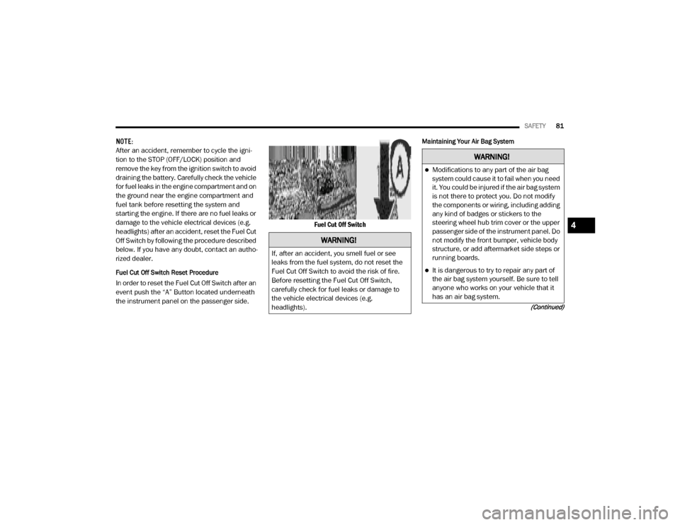
Fuel Cut Off Switch Reset Procedure
In order to reset the Fuel Cut Off Switch after an
event push the “A” Button located underneath
the instrument panel on the passenger side. Fuel Cut Off Switch
Maintaining Your Air Bag System
WARNING!
If, after an accident, you smell fuel or see
leaks from the fuel system, do not reset the
Fuel Cut Off Switch to avoid the risk of fire.
Before resetting the Fuel Cut Off Switch,
carefully check for fuel leaks or damage to
the vehicle electrical devices (e.g.
headlights).
WARNING!
Modifications to any part of the air bag
system could cause it to fail when you need
it. You could be injured if the air bag system
is not there to protect you. Do not modify
the components or wiring, including adding
any kind of badges or stickers to the
steering wheel hub trim cover or the upper
passenger side of the instrument panel. Do
not modify the front bumper, vehicle body
structure, or add aftermarket side steps or
running boards.
It is dangerous to try to repair any part of
the air bag system yourself. Be sure to tell
anyone who works on your vehicle that it
has an air bag system.
4
20_VF_OM_EN_US_t.book Page 81
Page 93 of 264
SAFETY91
(Continued)
Periodic Safety Checks You Should Make
Outside The Vehicle
Tires
Examine tires for excessive tread wear and
uneven wear patterns. Check for stones, nails,
glass, or other objects lodged in the tread or
sidewall. Inspect the tread for cuts and cracks.
Inspect sidewalls for cuts, cracks, and bulges.
Check the wheel bolts for tightness. Check the
tires (including spare) for proper cold inflation
pressure.
Lights
Have someone observe the operation of brake
lights and exterior lights while you work the
controls. Check turn signal and high beam indi -
cator lights on the instrument panel.
Door Latches
Check for proper closing, latching, and locking.
Fluid Leaks
Check area under the vehicle after overnight
parking for fuel, coolant, oil, or other fluid leaks.
Also, if gasoline fumes are detected or if fuel, or
brake fluid leaks are suspected, the cause
should be located and corrected immediately.
ONLY install floor mats designed to fit your
vehicle. NEVER install a floor mat that
cannot be properly attached and secured to
your vehicle. If a floor mat needs to be
replaced, only use a FCA approved floor
mat for the specific make, model, and year
of your vehicle.
ONLY use the driver’s side floor mat on the
driver’s side floor area. To check for inter -
ference, with the vehicle properly parked
with the engine off, fully depress the accel -
erator, the brake, and the clutch pedal (if
present) to check for interference. If your
floor mat interferes with the operation of
any pedal, or is not secure to the floor,
remove the floor mat from the vehicle and
place the floor mat in your trunk.
ONLY use the passenger’s side floor mat on
the passenger’s side floor area.
WARNING!
(Continued)
ALWAYS make sure objects cannot fall or
slide into the driver’s side floor area when
the vehicle is moving. Objects can become
trapped under accelerator, brake, or clutch
pedals and could cause a loss of vehicle
control.
NEVER place any objects under the floor
mat (e.g., towels, keys, etc.). These objects
could change the position of the floor mat
and may cause interference with the accel -
erator, brake, or clutch pedals.
If the vehicle carpet has been removed and
re-installed, always properly attach carpet
to the floor and check the floor mat
fasteners are secure to the vehicle carpet.
Fully depress each pedal to check for inter -
ference with the accelerator, brake, or
clutch pedals then re-install the floor mats.
It is recommended to only use mild soap
and water to clean your floor mats. After
cleaning, always check your floor mat has
been properly installed and is secured to
your vehicle using the floor mat fasteners
by lightly pulling mat.
WARNING!
(Continued)
4
20_VF_OM_EN_US_t.book Page 91