stop start Ram ProMaster 2020 Owner's Manual
[x] Cancel search | Manufacturer: RAM, Model Year: 2020, Model line: ProMaster, Model: Ram ProMaster 2020Pages: 264, PDF Size: 10.11 MB
Page 13 of 264
GETTING TO KNOW YOUR VEHICLE11
(Continued)
La operación de este equipo está sujeta a las
siguientes dos condiciones:
1. es posible que este equipo o dispositivo no
cause interferencia perjudicial y
2. este equipo o dispositivo debe aceptar cual -
quier interferencia, incluyendo la que
pueda causar su operación no deseada.
NOTE:
Changes or modifications not expressly
approved by the party responsible for compli -
ance could void the user’s authority to operate
the equipment.
IGNITION SWITCH
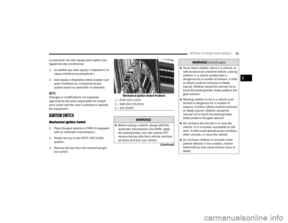
Mechanical Ignition Switch
1. Place the gear selector in PARK (if equipped with an automatic transmission).
2. Rotate the key to the STOP (OFF/LOCK) position.
3. Remove the key from the mechanical igni -
tion switch. Mechanical Ignition Switch Positions
1 — STOP (OFF/LOCK)
2 — MAR (ACC/ON/RUN)
3 — AVV (START)
WARNING!
Before exiting a vehicle, always shift the
automatic transmission into PARK, apply
the parking brake, turn the vehicle OFF,
remove the key fobs from vehicle, and lock
all doors and lock your vehicle.
Never leave children alone in a vehicle, or
with access to an unlocked vehicle. Leaving
children in a vehicle unattended is
dangerous for a number of reasons. A child
or others could be seriously or fatally
injured. Children should be warned not to
touch the parking brake, brake pedal or the
gear selector.
Allowing children to be in a vehicle unat
-
tended is dangerous for a number of
reasons. A child or others could be seriously
or fatally injured. Children should be
warned not to touch the parking brake,
brake pedal or the gear selector.
Do not leave the key fob in or near the
vehicle, or in a location accessible to chil -
dren. A child could operate power windows,
other controls, or move the vehicle.
Do not leave children or animals inside
parked vehicles in hot weather. Interior
heat build-up may cause serious injury or
death.
WARNING!
(Continued)
2
20_VF_OM_EN_US_t.book Page 11
Page 14 of 264

12GETTING TO KNOW YOUR VEHICLE
Key-In-Ignition Reminder
Opening the driver's door when the key is in the
ignition and the ignition switch position is STOP
(OFF/LOCK) sounds a signal to remove the key.
SENTRY KEY
The Sentry Key Immobilizer System prevents
unauthorized vehicle operation by disabling the
engine. The system does not need to be armed
or activated. Operation is automatic, regardless
of whether the vehicle is locked or unlocked.
The system uses ignition keys which have an
embedded electronic chip (transponder) to
prevent unauthorized vehicle operation. There -
fore, only keys that are programmed to the
vehicle can be used to start and operate the
vehicle. NOTE:
A key which has not been programmed is also
considered an invalid key, even if it is cut to fit
the ignition switch lock cylinder for that vehicle.
If the vehicle security light is on after the key is
turned to the MAR (ACC/ON/RUN) position, it
indicates that there is a problem with the elec
-
tronics.
All of the keys provided with your new vehicle
have been programmed to the vehicle elec -
tronics.
Replacement Keys
NOTE:
Only keys that have been programmed to the
vehicle electronics can be used to start the
vehicle. Once a Sentry Key has been
programmed to a vehicle, it cannot be
programmed to any other vehicle. When having
the Sentry Key Immobilizer System serviced,
bring all vehicle keys with you to an authorized
dealer.
The VIN is required for authorized dealer
replacement of keys. Duplication of keys may
be performed at an authorized dealer.
General Information
The following regulatory statement applies to all
Radio Frequency (RF) devices equipped in this
vehicle:
CAUTION!
An unlocked vehicle is an invitation. Always
remove the key from the ignition and lock all
the doors when leaving the vehicle
unattended.
CAUTION!
Always remove the Sentry Key from the
vehicle and lock all doors when leaving the
vehicle unattended.
The Sentry Key Immobilizer system is not
compatible with some aftermarket remote
starting systems. Use of these systems may
result in vehicle starting problems and loss
of security protection.
20_VF_OM_EN_US_t.book Page 12
Page 20 of 264
18GETTING TO KNOW YOUR VEHICLE
Swivel Seat — If Equipped
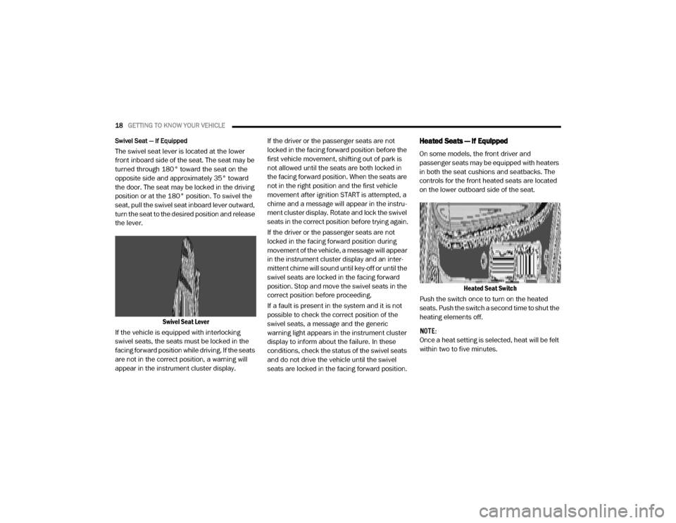
The swivel seat lever is located at the lower
front inboard side of the seat. The seat may be
turned through 180° toward the seat on the
opposite side and approximately 35° toward
the door. The seat may be locked in the driving
position or at the 180° position. To swivel the
seat, pull the swivel seat inboard lever outward,
turn the seat to the desired position and release
the lever.
Swivel Seat Lever
If the vehicle is equipped with interlocking
swivel seats, the seats must be locked in the
facing forward position while driving. If the seats
are not in the correct position, a warning will
appear in the instrument cluster display. If the driver or the passenger seats are not
locked in the facing forward position before the
first vehicle movement, shifting out of park is
not allowed until the seats are both locked in
the facing forward position. When the seats are
not in the right position and the first vehicle
movement after ignition START is attempted, a
chime and a message will appear in the instru
-
ment cluster display. Rotate and lock the swivel
seats in the correct position before trying again.
If the driver or the passenger seats are not
locked in the facing forward position during
movement of the vehicle, a message will appear
in the instrument cluster display and an inter -
mittent chime will sound until key-off or until the
swivel seats are locked in the facing forward
position. Stop and move the swivel seats in the
correct position before proceeding.
If a fault is present in the system and it is not
possible to check the correct position of the
swivel seats, a message and the generic
warning light appears in the instrument cluster
display to inform about the failure. In these
conditions, check the status of the swivel seats
and do not drive the vehicle until the swivel
seats are locked in the facing forward position.
Heated Seats — If Equipped
On some models, the front driver and
passenger seats may be equipped with heaters
in both the seat cushions and seatbacks. The
controls for the front heated seats are located
on the lower outboard side of the seat.
Heated Seat Switch
Push the switch once to turn on the heated
seats. Push the switch a second time to shut the
heating elements off.
NOTE:
Once a heat setting is selected, heat will be felt
within two to five minutes.
20_VF_OM_EN_US_t.book Page 18
Page 44 of 264
42GETTING TO KNOW YOUR INSTRUMENT PANEL
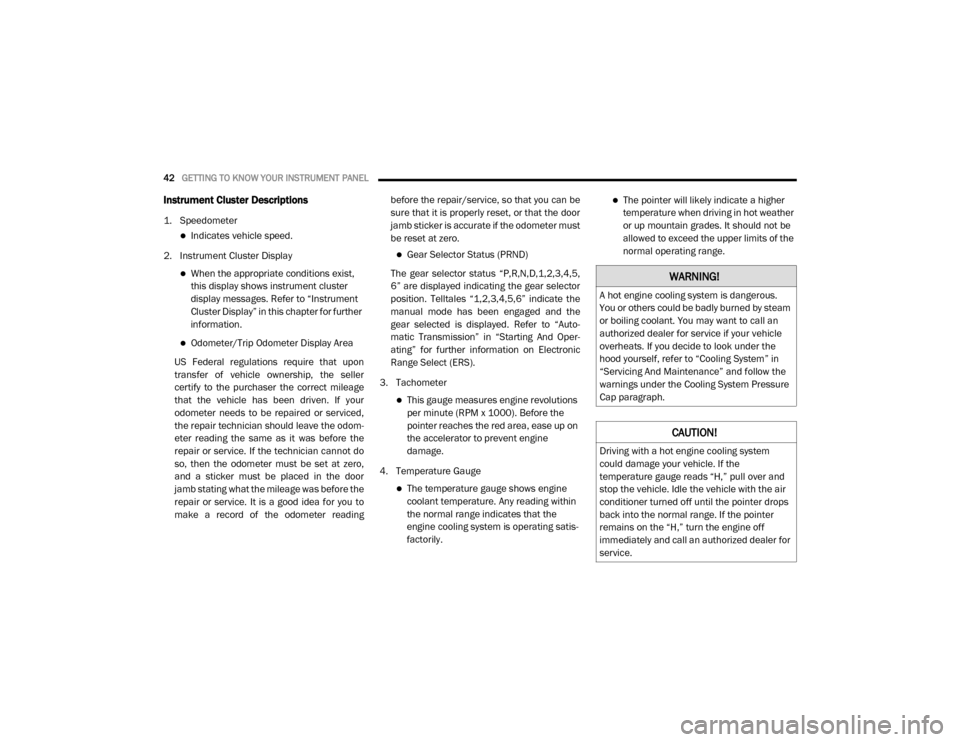
Instrument Cluster Descriptions
1. Speedometer
Indicates vehicle speed.
2. Instrument Cluster Display
When the appropriate conditions exist,
this display shows instrument cluster
display messages. Refer to “Instrument
Cluster Display” in this chapter for further
information.
Odometer/Trip Odometer Display Area
US Federal regulations require that upon
transfer of vehicle ownership, the seller
certify to the purchaser the correct mileage
that the vehicle has been driven. If your
odometer needs to be repaired or serviced,
the repair technician should leave the odom -
eter reading the same as it was before the
repair or service. If the technician cannot do
so, then the odometer must be set at zero,
and a sticker must be placed in the door
jamb stating what the mileage was before the
repair or service. It is a good idea for you to
make a record of the odometer reading before the repair/service, so that you can be
sure that it is properly reset, or that the door
jamb sticker is accurate if the odometer must
be reset at zero.
Gear Selector Status (PRND)
The gear selector status “P,R,N,D,1,2,3,4,5,
6” are displayed indicating the gear selector
position. Telltales “1,2,3,4,5,6” indicate the
manual mode has been engaged and the
gear selected is displayed. Refer to “Auto -
matic Transmission” in “Starting And Oper -
ating” for further information on Electronic
Range Select (ERS).
3. Tachometer
This gauge measures engine revolutions
per minute (RPM x 1000). Before the
pointer reaches the red area, ease up on
the accelerator to prevent engine
damage.
4. Temperature Gauge
The temperature gauge shows engine
coolant temperature. Any reading within
the normal range indicates that the
engine cooling system is operating satis-
factorily.
The pointer will likely indicate a higher
temperature when driving in hot weather
or up mountain grades. It should not be
allowed to exceed the upper limits of the
normal operating range.
WARNING!
A hot engine cooling system is dangerous.
You or others could be badly burned by steam
or boiling coolant. You may want to call an
authorized dealer for service if your vehicle
overheats. If you decide to look under the
hood yourself, refer to “Cooling System” in
“Servicing And Maintenance” and follow the
warnings under the Cooling System Pressure
Cap paragraph.
CAUTION!
Driving with a hot engine cooling system
could damage your vehicle. If the
temperature gauge reads “H,” pull over and
stop the vehicle. Idle the vehicle with the air
conditioner turned off until the pointer drops
back into the normal range. If the pointer
remains on the “H,” turn the engine off
immediately and call an authorized dealer for
service.
20_VF_OM_EN_US_t.book Page 42
Page 50 of 264
48GETTING TO KNOW YOUR INSTRUMENT PANEL
Electronic Throttle Control (ETC) Warning Light
This warning light will illuminate to
inform of a problem with the Elec -
tronic Throttle Control (ETC) system. If
a problem is detected while the
vehicle is running, the light will either stay on or
flash depending on the nature of the problem.
Cycle the ignition when the vehicle is safely and
completely stopped and the transmission is
placed in the PARK (P) position. The light should
turn off. If the light remains on with the vehicle
running, your vehicle will usually be drivable;
however, see an authorized dealer for service
as soon as possible.
If the light continues to flash when the vehicle is
running, immediate service is required and you
may experience reduced performance, an
elevated/rough idle, or engine stall and your
vehicle may require towing. The light will come
on when the ignition is placed in the ON/RUN or
MAR/ON/RUN position and remain on briefly as
a bulb check. If the light does not come on
during starting, have the system checked by an
authorized dealer.
Transmission Fault Warning Light
This light will illuminate (together with
a message in the instrument cluster
display and a buzzer) to indicate a
transmission fault. Contact an autho -
rized dealer if the message remains after
restarting the engine.
Engine Temperature Warning Light
This light warns of an overheated
engine condition. If the engine
coolant temperature is too high, this
indicator will illuminate and a single
chime will sound.
If the light turns on while driving, safely pull over
and stop the vehicle. If the A/C system is on,
turn it off. Also, shift the transmission into
NEUTRAL and idle the vehicle. If the tempera -
ture reading does not return to normal, turn the
engine off immediately and call for service.
Refer to “If Your Engine Overheats” in “In Case
Of Emergency” for further information.
Brake Warning Light
This warning light monitors various
brake functions, including brake
fluid level and parking brake appli -
cation. If the brake light turns on it
may indicate that the parking brake is
applied, that the brake fluid level is low, or
that there is a problem with the anti-lock
brake system reservoir.
If the light remains on when the parking brake
has been disengaged, and the fluid level is at
the full mark on the master cylinder reservoir, it
indicates a possible brake hydraulic system
malfunction or that a problem with the Brake
Booster has been detected by the Anti-Lock
Brake System (ABS) / Electronic Stability
Control (ESC) system. In this case, the light will
remain on until the condition has been
corrected. If the problem is related to the brake
booster, the ABS pump will run when applying
the brake, and a brake pedal pulsation may be
felt during each stop.
20_VF_OM_EN_US_t.book Page 48
Page 52 of 264
50GETTING TO KNOW YOUR INSTRUMENT PANEL
Yellow Warning Lights
Immobilizer Fail / VPS Electrical Alarm Indicator
Light
This telltale will illuminate when the
vehicle security alarm system has
detected an attempt to break into the
vehicle.
NOTE:
After cycling the ignition to the ON/RUN posi -
tion, the Vehicle Security Warning Light could
illuminate if a problem with the system is
detected. This condition will result in the engine
being shut off after two seconds.
Tire Pressure Monitoring System (TPMS) Warning
Light
The warning light switches on and a
message is displayed to indicate that
the tire pressure is lower than the
recommended value and/or that slow
pressure loss is occurring. In these cases,
optimal tire duration and fuel consumption may
not be guaranteed.
Should one or more tires be in the condition
mentioned above, the display will show the indi -
cations corresponding to each tire. Each tire, including the spare (if provided),
should be checked monthly when cold and
inflated to the inflation pressure recommended
by the vehicle manufacturer on the vehicle
placard or tire inflation pressure label. If your
vehicle has tires of a different size than the size
indicated on the vehicle placard or tire inflation
pressure label, you should determine the
proper tire inflation pressure for those tires.
As an added safety feature, your vehicle has
been equipped with a Tire Pressure Monitoring
System (TPMS) that illuminates a low tire pres
-
sure telltale when one or more of your tires is
significantly under-inflated. Accordingly, when
the low tire pressure telltale illuminates, you
should stop and check your tires as soon as possible, and inflate them to the proper pres
-
sure. Driving on a significantly under-inflated
tire causes the tire to overheat and can lead to
tire failure. Under-inflation also reduces fuel
efficiency and tire tread life, and may affect the
vehicle’s handling and stopping ability.
Please note that the TPMS is not a substitute for
proper tire maintenance, and it is the driver’s
responsibility to maintain correct tire pressure,
even if under-inflation has not reached the level
to trigger illumination of the TPMS low tire pres -
sure telltale.
Your vehicle has also been equipped with a
TPMS malfunction indicator to indicate when
the system is not operating properly. The TPMS
malfunction indicator is combined with the low
tire pressure telltale. When the system detects
a malfunction, the telltale will flash for approxi -
mately one minute and then remain continu -
ously illuminated. This sequence will continue
upon subsequent vehicle start-ups as long as
the malfunction exists. When the malfunction
indicator is illuminated, the system may not be
able to detect or signal low tire pressure as
intended. TPMS malfunctions may occur for a
variety of reasons, including the installation of
CAUTION!
Do not continue driving with one or more flat
tires as handling may be compromised. Stop
the vehicle, avoiding sharp braking and
steering. If a tire puncture occurs, repair
immediately using the dedicated tire repair
kit and contact an authorized dealer as soon
as possible.
20_VF_OM_EN_US_t.book Page 50
Page 53 of 264
GETTING TO KNOW YOUR INSTRUMENT PANEL51
replacement or alternate tires or wheels on the
vehicle that prevent the TPMS from functioning
properly. Always check the TPMS malfunction
telltale after replacing one or more tires or
wheels on your vehicle to ensure that the
replacement or alternate tires and wheels allow
the TPMS to continue to function properly.Electronic Stability Control (ESC) Warning Light
The “ESC Indicator Light” in the instru-
ment cluster will come on when the
ignition is placed in the ON/RUN or
MAR (ACC/ON/RUN) position, and
when ESC is activated. It should turn off with the
engine running. If the “ESC Indicator Light”
comes on continuously with the engine running,
a malfunction has been detected in the ESC
system. If this light remains on after several
ignition cycles, and the vehicle has been driven
several miles (kilometers) at speeds greater
than 30 mph (48 km/h), see an authorized
dealer as soon as possible to have the problem
diagnosed and corrected.
The “ESC OFF Indicator Light” and the “ESC
Indicator Light” come on momentarily each
time the ignition is placed in the ON/RUN or
MAR (ACC/ON/RUN) position.
Each time the ignition is turned to ON/RUN or
MAR (ACC/ON/RUN), the ESC system will be
on, even if it was turned off previously.
The ESC system will make buzzing or clicking
sounds when it is active. This is normal; the
sounds will stop when ESC becomes inactive.
This light will come on when the vehicle is in
an ESC event.
Electronic Stability Control (ESC) OFF Warning
Light
This light indicates the Electronic
Stability Control (ESC) is off.
Each time the ignition is turned to ON/RUN or
MAR/ON/RUN, the ESC system will be on, even
if it was turned off previously.
Engine Check/Malfunction Indicator Warning Light
(MIL)
The Engine Check/Malfunction Indi -
cator Light (MIL) is a part of an
Onboard Diagnostic System called
OBD II that monitors engine and auto -
matic transmission control systems. This
warning light will illuminate when the ignition is
in the ON/RUN position before engine start. If
the bulb does not come on when turning the
ignition switch from OFF to ON/RUN, have the
condition checked promptly.
CAUTION!
The TPMS has been optimized for the original
equipment tires and wheels. TPMS pressures
and warning have been established for the
tire size equipped on your vehicle.
Undesirable system operation or sensor
damage may result when using replacement
equipment that is not of the same size, type,
and/or style. Aftermarket wheels can cause
sensor damage. Using aftermarket tire
sealants may cause the Tire Pressure
Monitoring System (TPMS) sensor to become
inoperable. After using an aftermarket tire
sealant it is recommended that you take your
vehicle to an authorized dealer to have your
sensor function checked.
3
20_VF_OM_EN_US_t.book Page 51
Page 54 of 264
52GETTING TO KNOW YOUR INSTRUMENT PANEL
Certain conditions, such as a loose or missing
gas cap, poor quality fuel, etc., may illuminate
the light after engine start. The vehicle should
be serviced if the light stays on through several
typical driving styles. In most situations, the
vehicle will drive normally and will not require
towing.
When the engine is running, the MIL may flash
to alert serious conditions that could lead to
immediate loss of power or severe catalytic
converter damage. The vehicle should be
serviced by an authorized dealer as soon as
possible if this occurs.
Anti-Lock Brake (ABS) Warning Light
This light monitors the Anti-Lock
Brake System (ABS). The light will turn
on when the ignition is placed in the
ON/RUN or MAR/ON/RUN position
and may stay on for as long as four seconds.
If the ABS light remains on or turns on while
driving, then the Anti-Lock portion of the brake
system is not functioning and service is
required. However, the conventional brake
system will continue to operate normally if the
brake warning light is not on.
If the ABS light is on, the brake system should
be serviced as soon as possible to restore the
benefits of Anti-Lock Brakes. If the ABS light
does not turn on when the ignition is placed in
the ON/RUN or MAR/ON/RUN position, have
the light inspected by an authorized dealer.
Generic Warning Light
The Generic Warning Light will illumi -
nate if any of the following conditions
occur: Engine Oil Pressure Sensor
Failure, External Light Failure, Fuel
Cut-Off intervention or fail, Parking Sensor
Failure, DST System Failure.
The telltale will remain on fixed in case of swivel
seat failure and on blinking in case of Air Bag
Warning Light Failure. Contact an authorized
dealer immediately for service.
Yellow Indicator Lights
Stop Light Failure Indicator Light
This light will illuminate if one or more
of the stop light bulb fails.
The failure relating to this light could be:
One or more blown bulbs.
A blown protection fuse.
A break in the electrical connection.
WARNING!
A malfunctioning catalytic converter, as
referenced above, can reach higher
temperatures than in normal operating
conditions. This can cause a fire if you drive
slowly or park over flammable substances
such as dry plants, wood, cardboard, etc. This
could result in death or serious injury to the
driver, occupants or others.
CAUTION!
Prolonged driving with the Malfunction
Indicator Light (MIL) on could cause damage
to the vehicle control system. It also could
affect fuel economy and driveability. If the
MIL is flashing, severe catalytic converter
damage and power loss will soon occur.
Immediate service is required.
20_VF_OM_EN_US_t.book Page 52
Page 59 of 264
SAFETY57
Electronic Brake Control (EBC) System
Your vehicle is equipped with an advanced Elec -
tronic Brake Control (EBC) system that includes
the Traction Control System (TCS), Brake Assist
System (BAS) and Electronic Stability Control
(ESC), Trailer Sway Control (TSC), and Hill Start
Assist (HSA). These systems complement the
Anti-Lock Brake System (ABS) by optimizing the
vehicle braking capability during emergency
braking maneuvers.
Brake Assist System (BAS)
The Brake Assist Sys tem (BAS) is designed to
optimize the vehicle’s braking c apability
during e merg ency braking maneuvers. The
system detects an emergency braking situa -
tio n by sensing the rate and am ount of brake
applic ation and then applies optimum pres -
sure to the brakes. This can help reduce
braking distance s. The BAS complements
the Anti-Lock Brake System (ABS). Applying
the brakes very quickly res ults in the best
BAS assistance . To rec eive the be ne fit of the
system , yo u must apply continuous braking pressure during the stopping sequence (do
not “pum p” the brakes). Do not reduce brake
pedal pre ssure unless braking is no longer
desired. Onc e the brake pedal is released,
the BAS is deac tivated.
Electronic Stability Control (ESC)
The Electronic Stability Control (ESC) enhances
directional control and stability of the vehicle
under various driving conditions. ESC corrects
for over/under steering of the vehicle by
applying the brake of the appropriate wheel to
assist in counteracting the over/under steer
condition. Engine power may also be reduced to
help the vehicle maintain the desired path.
ESC uses sensors in the vehicle to determine
the vehicle path intended by the driver and
compares it to the actual path of the vehicle.
When the actual path does not match the
intended path, ESC applies the brake of the
appropriate wheel to assist in counteracting the
oversteer or understeer condition.
Oversteer - when the vehicle is turning more
than appropriate for the steering wheel posi
-
tion.
Understeer - when the vehicle is turning
less than appropriate for the steering
wheel position.
WARNING!
The Brake Assist System (BAS) cannot
prevent the natural laws of physics from
acting on the vehicle, nor can it increase the
traction afforded by prevailing road
conditions. BAS cannot prevent collisions,
including those resulting from excessive
speed in turns, driving on very slippery
surfaces, or hydroplaning. The capabilities of
a BAS-equipped vehicle must never be
exploited in a reckless or dangerous manner,
which could jeopardize the user's safety or
the safety of others.
4
20_VF_OM_EN_US_t.book Page 57
Page 62 of 264
60SAFETY
(Continued)
Hill Start Assist (HSA)
The Hill Start Assist (HSA) system is designed to
assist the driver when starting a vehicle from a stop
on a hill. HSA will maintain the level of brake pres -
sure the driver applied for a short period of time
after the driver takes their foot off of the brake
pedal. If the driver does not apply the throttle during
this short period of time, the system will release
brake pressure and the vehicle will roll down the hill.
The system will release brake pressure in proportion
to the amount of throttle applied as the vehicle
starts to move in the intended direction of travel.
HSA Activation Criteria
The following criteria must be met in order for HSA
to activate:
Vehicle must be stopped
Vehicle must be on a 6% (approximate) grade or
greater hill
Gear selection matches vehicl e uphill direction
(i.e., vehicle facing uphill is in forward gear;
vehicle backing uphill is in REVERSE (R) gear)
HSA will work in REVERSE and all forward gears
when the activation criteria have been met. The
system will not activate if the vehicle is placed in
NEUTRAL (N) or PARK (P).
Towing With HSA
HSA will also provide assistance to mitigate roll
back while towing a trailer.
Traction Control System (TCS)
The Traction Control System (TCS) monitors the
amount of wheel spin of each of the driven
wheels. If wheel spin is detected, brake pressure
is applied to the slipping wheel(s) and engine
power is reduced, to provide enhanced accelera -
tion and stability. A feature of the TCS system,
Brake Limited Differential (BLD), functions
similar to a limited slip differential and controls
the wheel spin across a driven axle. If one wheel
on a driven axle is spinning faster than the other,
the system will apply the brake of the spinning
wheel. This will allow more engine torque to be
applied to the wheel that is not spinning. This
feature remains active even if the ESC is in the
“Partial Off” mode.
WARNING!
There may be situations on minor hills with
a loaded vehicle, or while pulling a trailer,
when the system will not activate and slight
rolling may occur. This could cause a
collision with another vehicle or object.
Always remember the driver is responsible
for braking the vehicle.
WARNING!
If you use a trailer brake controller with
your trailer, the trailer brakes may be acti -
vated and deactivated with the brake
switch. If so, there may not be enough
brake pressure to hold both the vehicle
and the trailer on a hill when the brake
pedal is released. In order to avoid rolling
down an incline while resuming accelera -
tion, manually activate the trailer brake
or apply more vehicle brake pressure
prior to releasing the brake pedal.
HSA is not a parking brake. Always apply
the parking brake fully when exiting your
vehicle. Also, be certain to place the trans -
mission in PARK.
Failure to follow these warnings can result
in a collision or serious personal injury.
WARNING!
(Continued)
20_VF_OM_EN_US_t.book Page 60