ESP Ram ProMaster 2020 Owner's Manual
[x] Cancel search | Manufacturer: RAM, Model Year: 2020, Model line: ProMaster, Model: Ram ProMaster 2020Pages: 264, PDF Size: 10.11 MB
Page 2 of 264
WARNING: Operating, servicing and maintaining a passenger vehicle or off-highway
motor vehicle can expose you to chemicals including engine exhaust, carbon monoxide,
phthalates, and lead, which are known to the State of California to cause cancer and birth defects
or other reproductive harm. To minimize exposure, avoid breathing exhaust, do not idle the
engine except as necessary, service your vehicle in a well-ventilated area and wear gloves or wash
your hands frequently when servicing your vehicle. For more information go to
www.P65Warnings.ca.gov/passenger-vehicle.
This Owner’s Manual illustrates and describes the operation of features and equipment that are either standard or optional on this vehicle. This manual may
also include a description of features and equipment that are no longer available or were not ordered on this vehicle. Please disregard any features and
equipment that are no longer available or were not ordered on this vehicle. FCA US LLC reserves the right to make changes in design and specifications, and/or make additions to or improvements to its products without imposing any obligation upon itself to install them on products previously manufactured.
With respect to vehicles sold in Canada, the name FCA US LLC shall be deemed to be deleted and the name FCA Canada Inc. used in substitution therefore.
If you are the first registered retail owner of your vehicle, you may obtain a complimentary printed copy of the Warranty Booklet by calling
1-866-726-4636 (U.S.) or 1-800-387-1143 (Canada), or by contacting your dealer.
This Owner’s Manual is intended to familiarize you with the important features of your vehicle. Your most up-to-date Owner’s Manual, Navigation/Uconnect manuals and Warranty Booklet can be found by visiting the website on the back cover. U.S. residents can purchase replacement kits by visiting www.techauthority.com and Canadian residents can purchase replacement kits by calling 1-800-387-1143.
Page 6 of 264

4
VEHICLE LOADING ................................................112
Vehicle Certification Label ............................... 112
Gross Vehicle Weight Rating (GVWR) .............. 112
Gross Axle Weight Rating (GAWR) .................. 112
Tire Size .............................................................112
Rim Size ............................................................ 112
Inflation Pressure ............................................. 112
Curb Weight ...................................................... 112
Overloading ....................................................... 112
Loading .............................................................113
TRAILER TOWING ..................................................113
Common Towing Definitions ............................113
Trailer Hitch Classification ............................... 114
Trailer Towing Weights
(Maximum Trailer Weight Ratings) ................. 115 Trailer And Tongue Weight ..............................115Towing Requirements ..................................... 116
Towing Tips ...................................................... 118
RECREATIONAL TOWING
(BEHIND MOTORHOME, ETC.) ............................120
Towing This Vehicle Behind Another Vehicle .. 120
Recreational Towing ......................................... 120
DRIVING TIPS.........................................................121
Driving On Slippery Surfaces ..........................121
Driving Through Water ....................................121
IN CASE OF EMERGENCY
HAZARD WARNING FLASHERS ..........................123 BULB REPLACEMENT ........................................... 123
Replacement Bulbs .......................................... 123
Replacing Exterior Bulbs .................................. 125
Replacing Interior Bulbs .................................. 127
FUSES..................................................................... 128
Underhood Fuses ............................................. 128
Interior Fuses.................................................... 131
Right Central Pillar Fuses ................................ 132
JACKING AND TIRE CHANGING .......................... 133
Jack Location .................................................... 133
Spare Tire Removal .......................................... 134
Preparations For Jacking ................................. 135
Jacking Instructions ......................................... 136Wheel Covers .................................................... 139
TIRE SERVICE KIT — IF EQUIPPED ...................... 139
Tire Service Kit Storage ................................... 139
Tire Service Kit Components And Operation .. 140Tire Service Kit Usage Precautions ................. 140
Sealing A Tire With Tire Service Kit ................. 142
JUMP STARTING ................................................... 145
Preparations For Jump Start ........................... 145
Jump Starting Procedure ................................. 146
Battery Location ............................................... 147
IF YOUR ENGINE OVERHEATS ............................ 147
GEAR SELECTOR OVERRIDE .............................. 148FREEING A STUCK VEHICLE ............................... 149
TOWING A DISABLED VEHICLE........................... 149
Automatic Transmission .................................. 150
ENHANCED ACCIDENT RESPONSE SYSTEM
(EARS) ....................................................................151
EVENT DATA RECORDER (EDR) .......................... 151
SERVICING AND MAINTENANCE
SCHEDULED SERVICING .....................................152
Maintenance Plan ............................................ 152
Heavy Duty Use Of The Vehicle ....................... 155
ENGINE COMPARTMENT...................................... 156
3.6L Engine ..................................................... 156
Checking Oil Level — Gas Engine ................... 157
Adding Washer Fluid ........................................ 157Maintenance-Free Battery .............................. 157
Pressure Washing ............................................ 158
DEALER SERVICE ................................................. 158
Engine Oil ......................................................... 158Engine Oil Filter ................................................ 159
Engine Air Cleaner Filter ................................. 159
Air Conditioner Maintenance ......................... 160
Body Lubrication .............................................. 161
Windshield Wiper Blades ................................ 162
Exhaust System ............................................... 162
Cooling System................................................. 163
Brake System .................................................. 166
Automatic Transmission
(3.6L Gasoline Engine Only) ............................ 167
RAISING THE VEHICLE..........................................168
20_VF_OM_EN_US_t.book Page 4
Page 13 of 264
GETTING TO KNOW YOUR VEHICLE11
(Continued)
La operación de este equipo está sujeta a las
siguientes dos condiciones:
1. es posible que este equipo o dispositivo no
cause interferencia perjudicial y
2. este equipo o dispositivo debe aceptar cual -
quier interferencia, incluyendo la que
pueda causar su operación no deseada.
NOTE:
Changes or modifications not expressly
approved by the party responsible for compli -
ance could void the user’s authority to operate
the equipment.
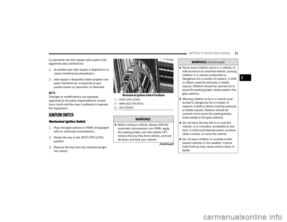
IGNITION SWITCH
Mechanical Ignition Switch
1. Place the gear selector in PARK (if equipped with an automatic transmission).
2. Rotate the key to the STOP (OFF/LOCK) position.
3. Remove the key from the mechanical igni -
tion switch. Mechanical Ignition Switch Positions
1 — STOP (OFF/LOCK)
2 — MAR (ACC/ON/RUN)
3 — AVV (START)
WARNING!
Before exiting a vehicle, always shift the
automatic transmission into PARK, apply
the parking brake, turn the vehicle OFF,
remove the key fobs from vehicle, and lock
all doors and lock your vehicle.
Never leave children alone in a vehicle, or
with access to an unlocked vehicle. Leaving
children in a vehicle unattended is
dangerous for a number of reasons. A child
or others could be seriously or fatally
injured. Children should be warned not to
touch the parking brake, brake pedal or the
gear selector.
Allowing children to be in a vehicle unat
-
tended is dangerous for a number of
reasons. A child or others could be seriously
or fatally injured. Children should be
warned not to touch the parking brake,
brake pedal or the gear selector.
Do not leave the key fob in or near the
vehicle, or in a location accessible to chil -
dren. A child could operate power windows,
other controls, or move the vehicle.
Do not leave children or animals inside
parked vehicles in hot weather. Interior
heat build-up may cause serious injury or
death.
WARNING!
(Continued)
2
20_VF_OM_EN_US_t.book Page 11
Page 15 of 264

GETTING TO KNOW YOUR VEHICLE13
This device complies with Part 15 of the FCC
Rules and with Innovation, Science and
Economic Development Canada license-exempt
RSS standard(s). Operation is subject to the
following two conditions:
1. This device may not cause harmful interfer -
ence, and
2. This device must accept any interference received, including interference that may
cause undesired operation.
Le présent appareil est conforme aux CNR
d`Innovation, Science and Economic Develop -
ment applicables aux appareils radio exempts
de licence. L'exploitation est autorisée aux deux
conditions suivantes:
1. l'appareil ne doit pas produire de brouillage, et
2. l'utilisateur de l'appareil doit accepter tout brouillage radioélectrique subi, même si le
brouillage est susceptible d'en comprom -
ettre le fonctionnement. La operación de este equipo está sujeta a las
siguientes dos condiciones:
1. es posible que este equipo o dispositivo no
cause interferencia perjudicial y
2. este equipo o dispositivo debe aceptar cual -
quier interferencia, incluyendo la que
pueda causar su operación no deseada.
NOTE:
Changes or modifications not expressly
approved by the party responsible for compli -
ance could void the user’s authority to operate
the equipment.
VEHICLE SECURITY ALARM — IF EQUIPPED
The vehicle security alarm monitors the vehicle
doors and ignition for unauthorized operation.
When the vehicle security alarm is activated,
interior switches for door locks are disabled.
The system provides both audible and visible
signals. For the first three minutes, the horn will
sound, and the turn signal lights will flash. For
an additional 15 minutes, only the turn signal
lights will flash.
To Arm The System
To arm the system, the vehicle security alarm
will set when you use the key fob to lock the
doors. If a door or the hood is not properly shut,
the alarm system will not be armed.
To Disarm The System
Use the key fob to unlock the door and disarm
the system.
The vehicle security alarm will also disarm if a
programmed Sentry Key is inserted into the igni -
tion switch. To exit the alarming mode, push the
key fob unlock button, or insert a programmed
Sentry Key into the ignition switch.
The vehicle security alarm is designed to protect
your vehicle. However, you can create condi -
tions where the system will give you a false
alarm. If one of the previously described arming
sequences has occurred, the vehicle security
alarm will arm regardless of whether you are in
the vehicle or not. If you remain in the vehicle
and open a door, the alarm will sound. If this
occurs, disarm the vehicle security alarm.
2
20_VF_OM_EN_US_t.book Page 13
Page 21 of 264
GETTING TO KNOW YOUR VEHICLE19
Fold Down Tray — If Equipped
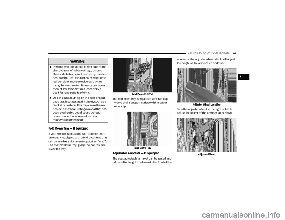
If your vehicle is equipped with a bench seat,
the seat is equipped with a fold-down tray that
can be used as a document support surface. To
use the fold-down tray, grasp the pull tab and
lower the tray. Fold-Down Pull Tab
The fold-down tray is equipped with two cup
holders and a support surface with a paper
holder clip.
Fold-Down Tray
Adjustable Armrests — If Equipped
The seat adjustable armrest can be raised and
adjusted for height. Underneath the front of the armrest is the adjuster wheel which will adjust
the height of the armrest up or down.
Adjuster Wheel Location
Turn the adjuster wheel to the right or left to
adjust the height of the armrest up or down.
Adjuster Wheel
WARNING!
Persons who are unable to feel pain to the
skin because of advanced age, chronic
illness, diabetes, spinal cord injury, medica -
tion, alcohol use, exhaustion or other phys -
ical condition must exercise care when
using the seat heater. It may cause burns
even at low temperatures, especially if
used for long periods of time.
Do not place anything on the seat or seat -
back that insulates against heat, such as a
blanket or cushion. This may cause the seat
heater to overheat. Sitting in a seat that has
been overheated could cause serious
burns due to the increased surface
temperature of the seat.
2
20_VF_OM_EN_US_t.book Page 19
Page 26 of 264

24GETTING TO KNOW YOUR VEHICLE
Daytime Running Lights (DRLs) — If
Equipped
NOTE:
When the headlights are turned on, the Daytime
Running Lights will be deactivated.
To activate the Daytime Running Lights (DRLs),
rotate the end of the multifunction lever to the
O (off) position.
NOTE:
The low beams and side/taillights will not be
on with DRLs.
In certain markets, the DRLs may be optional
and can be programmed to be on or off
through the Uconnect system screen. Refer
to “Uconnect Settings” in “Multimedia” for
further information.
The Daytime Running Lights will come on when -
ever the ignition is ON, the headlight switch is
off, and the turn signal is off.
High Beam/Low Beam Select Switch
With the low beams activated, pull the multi -
function lever toward the steering wheel to
switch the headlights to high beam. A high
beam symbol will be illuminated in the cluster to
indicate the high beams are on. Pull the lever a
second time to switch the headlights back to
low beam.
NOTE:
If the vehicle’s ignition is placed in the STOP
(OFF/LOCK) position, both high and low beam
headlights will also be turned off.
Flash-To-Pass
You can signal another vehicle with your head -
lights by partially pulling the multifunction lever
toward the steering wheel. This will cause the
high beam headlights to turn on until the lever
is released.
Parking Lights
These lights can only be turned on with ignition
key in the STOP (OFF/LOCK) position or
removed, by moving the end of the multifunc -
tion lever to O (off) position and then to the
headlight position. The warning light telltale in the instrument
panel comes on. The lights stay on until the next
ignition cycle is performed.
Follow Me Home/Headlight Delay
When this feature is selected, the driver can
choose to have the headlights remain on for a
preset period of time.
Activation
Remove the key or turn the ignition to the STOP
(OFF/LOCK) position, and pull the multifunction
lever toward the steering wheel, within two
minutes. Each time the lever is pulled, the acti
-
vation of the lights will be extended by 30
seconds. The activation of the lights can be
extended to a maximum of 210 seconds.
The warning light on the instrument panel will
light up and the corresponding message will
appear in the instrument cluster display for as
long as the function is activated. The warning
light comes on when the lever is operated and
stays on until the function is automatically deac -
tivated. Each movement of the lever only
increases the amount of time the lights stay on.
Deactivation
Pull the multifunction lever toward the steering
wheel and hold it for more than two seconds.
20_VF_OM_EN_US_t.book Page 24
Page 27 of 264
GETTING TO KNOW YOUR VEHICLE25
Fog Lights — If Equipped
The fog light switch is located on the center
stack of the instrument panel, just below the
climate controls. Push the switch once to turn
the fog lights on. Push the switch a second time
to turn the fog lights off.
NOTE:
If the vehicle’s ignition is placed in the STOP
(OFF/LOCK) position, the fog lights will also turn
off.
Turn Signals
Move the multifunction lever up or down and
the arrows on each side of the instrument
cluster flash to show proper operation of the
front and rear turn signal lights.
NOTE:
If either light remains on and does not flash, or
there is a very fast flash rate, check for a defec -
tive outside light bulb. If an indicator fails to
light when the lever is moved, it would suggest
that the indicator bulb is defective.
Lane Change Assist
Tap the lever up or down once, without moving
beyond the detent, and the turn signal (right or
left) will flash five times then automatically turn
off.
Battery Saver
To protect the life of your vehicle’s battery,
when the ignition is OFF and any door is left ajar
for 15 minutes, the interior lights will automati -
cally turn off.
NOTE:
Battery saver mode is cancelled if the ignition is
placed in the MAR (ACC/ON/RUN).
INTERIOR LIGHTS
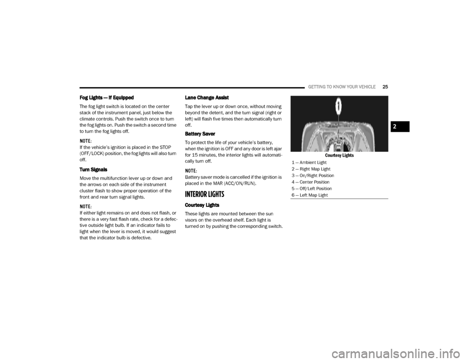
Courtesy Lights
These lights are mounted between the sun
visors on the overhead shelf. Each light is
turned on by pushing the corresponding switch. Courtesy Lights
1 — Ambient Light
2 — Right Map Light
3 — On/Right Position
4 — Center Position
5 — Off/Left Position
6 — Left Map Light
2
20_VF_OM_EN_US_t.book Page 25
Page 52 of 264
50GETTING TO KNOW YOUR INSTRUMENT PANEL
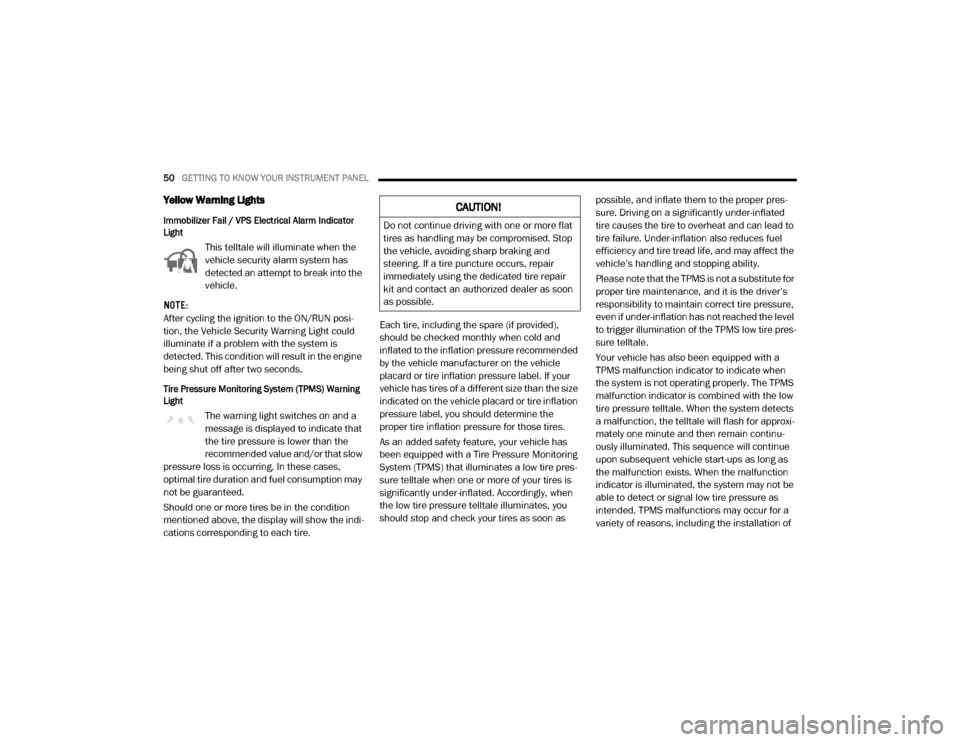
Yellow Warning Lights
Immobilizer Fail / VPS Electrical Alarm Indicator
Light
This telltale will illuminate when the
vehicle security alarm system has
detected an attempt to break into the
vehicle.
NOTE:
After cycling the ignition to the ON/RUN posi -
tion, the Vehicle Security Warning Light could
illuminate if a problem with the system is
detected. This condition will result in the engine
being shut off after two seconds.
Tire Pressure Monitoring System (TPMS) Warning
Light
The warning light switches on and a
message is displayed to indicate that
the tire pressure is lower than the
recommended value and/or that slow
pressure loss is occurring. In these cases,
optimal tire duration and fuel consumption may
not be guaranteed.
Should one or more tires be in the condition
mentioned above, the display will show the indi -
cations corresponding to each tire. Each tire, including the spare (if provided),
should be checked monthly when cold and
inflated to the inflation pressure recommended
by the vehicle manufacturer on the vehicle
placard or tire inflation pressure label. If your
vehicle has tires of a different size than the size
indicated on the vehicle placard or tire inflation
pressure label, you should determine the
proper tire inflation pressure for those tires.
As an added safety feature, your vehicle has
been equipped with a Tire Pressure Monitoring
System (TPMS) that illuminates a low tire pres
-
sure telltale when one or more of your tires is
significantly under-inflated. Accordingly, when
the low tire pressure telltale illuminates, you
should stop and check your tires as soon as possible, and inflate them to the proper pres
-
sure. Driving on a significantly under-inflated
tire causes the tire to overheat and can lead to
tire failure. Under-inflation also reduces fuel
efficiency and tire tread life, and may affect the
vehicle’s handling and stopping ability.
Please note that the TPMS is not a substitute for
proper tire maintenance, and it is the driver’s
responsibility to maintain correct tire pressure,
even if under-inflation has not reached the level
to trigger illumination of the TPMS low tire pres -
sure telltale.
Your vehicle has also been equipped with a
TPMS malfunction indicator to indicate when
the system is not operating properly. The TPMS
malfunction indicator is combined with the low
tire pressure telltale. When the system detects
a malfunction, the telltale will flash for approxi -
mately one minute and then remain continu -
ously illuminated. This sequence will continue
upon subsequent vehicle start-ups as long as
the malfunction exists. When the malfunction
indicator is illuminated, the system may not be
able to detect or signal low tire pressure as
intended. TPMS malfunctions may occur for a
variety of reasons, including the installation of
CAUTION!
Do not continue driving with one or more flat
tires as handling may be compromised. Stop
the vehicle, avoiding sharp braking and
steering. If a tire puncture occurs, repair
immediately using the dedicated tire repair
kit and contact an authorized dealer as soon
as possible.
20_VF_OM_EN_US_t.book Page 50
Page 62 of 264
60SAFETY
(Continued)
Hill Start Assist (HSA)
The Hill Start Assist (HSA) system is designed to
assist the driver when starting a vehicle from a stop
on a hill. HSA will maintain the level of brake pres -
sure the driver applied for a short period of time
after the driver takes their foot off of the brake
pedal. If the driver does not apply the throttle during
this short period of time, the system will release
brake pressure and the vehicle will roll down the hill.
The system will release brake pressure in proportion
to the amount of throttle applied as the vehicle
starts to move in the intended direction of travel.
HSA Activation Criteria
The following criteria must be met in order for HSA
to activate:
Vehicle must be stopped
Vehicle must be on a 6% (approximate) grade or
greater hill
Gear selection matches vehicl e uphill direction
(i.e., vehicle facing uphill is in forward gear;
vehicle backing uphill is in REVERSE (R) gear)
HSA will work in REVERSE and all forward gears
when the activation criteria have been met. The
system will not activate if the vehicle is placed in
NEUTRAL (N) or PARK (P).
Towing With HSA
HSA will also provide assistance to mitigate roll
back while towing a trailer.
Traction Control System (TCS)
The Traction Control System (TCS) monitors the
amount of wheel spin of each of the driven
wheels. If wheel spin is detected, brake pressure
is applied to the slipping wheel(s) and engine
power is reduced, to provide enhanced accelera -
tion and stability. A feature of the TCS system,
Brake Limited Differential (BLD), functions
similar to a limited slip differential and controls
the wheel spin across a driven axle. If one wheel
on a driven axle is spinning faster than the other,
the system will apply the brake of the spinning
wheel. This will allow more engine torque to be
applied to the wheel that is not spinning. This
feature remains active even if the ESC is in the
“Partial Off” mode.
WARNING!
There may be situations on minor hills with
a loaded vehicle, or while pulling a trailer,
when the system will not activate and slight
rolling may occur. This could cause a
collision with another vehicle or object.
Always remember the driver is responsible
for braking the vehicle.
WARNING!
If you use a trailer brake controller with
your trailer, the trailer brakes may be acti -
vated and deactivated with the brake
switch. If so, there may not be enough
brake pressure to hold both the vehicle
and the trailer on a hill when the brake
pedal is released. In order to avoid rolling
down an incline while resuming accelera -
tion, manually activate the trailer brake
or apply more vehicle brake pressure
prior to releasing the brake pedal.
HSA is not a parking brake. Always apply
the parking brake fully when exiting your
vehicle. Also, be certain to place the trans -
mission in PARK.
Failure to follow these warnings can result
in a collision or serious personal injury.
WARNING!
(Continued)
20_VF_OM_EN_US_t.book Page 60
Page 65 of 264
SAFETY63
The TPMS is not a substitute for proper tire
maintenance, and it is the driver’s responsi -
bility to maintain correct tire pressure using
an accurate tire pressure gauge, even if
under-inflation has not reached the level to
trigger illumination of the TPMS Warning
Light.
Seasonal temperature changes will affect
tire pressure, and the TPMS will monitor the
actual tire pressure in the tire.
Base System
This is the TPMS warning indicator
located in the instrument cluster.
The TPMS uses wireless technology
with wheel rim mounted electronic
sensors to monitor tire pressure levels.
Sensors, mounted to each wheel as part of the
valve stem, transmit tire pressure readings to
the Receiver Module.
NOTE:
It is particularly important for you to check the
tire pressure in all of the tires on your vehicle
regularly and to maintain the proper pressure.
The TPMS consists of the following components:
Receiver Module
Four Tire Pressure Monitoring sensors
Tire Pressure Monitoring System Warning
Light
Tire Pressure Monitoring Low Pressure Warnings
The Tire Pressure Monitoring System Warning
Light will illuminate in the instrument cluster, an
audible chime will be activated, and the “Check
tire pressure” message will display when one or
more of the four active road tire pressures are
low. Should this occur, you should stop as soon
as possible, check the inflation pressure of
each tire on your vehicle, and inflate each tire to
the vehicle’s recommended cold placard pres
-
sure value. The system will automatically
update and the Tire Pressure Monitoring Light
will extinguish once the updated tire pressures
have been received. The vehicle may need to be
driven for up to 20 minutes above 15 mph
(24 km/h) to receive this information.
Check TPMS Warnings
The Tire Pressure Monitoring System Warning
Light will flash on and off for 75 seconds and
remain on solid when a system fault is detected,
an audible chime will be activated and the “Tire
Pressure Monitoring Unavailable” message will
display. If the ignition key is cycled, this
sequence will repeat providing the system fault
still exists. The TPMS Warning Light will turn off
when the fault condition no longer exists. A
system fault can occur with any of the following
scenarios:
Jamming due to electronic devices or driving
next to facilities emitting the same radio
frequencies as the TPM sensors
Installing some form of aftermarket window
tinting that affects radio wave signals
Snow or ice around the wheels or wheel
housings
Using tire chains on the vehicle
Using wheels/tires not equipped with TPM
sensors
4
20_VF_OM_EN_US_t.book Page 63