display RAM PROMASTER 2021 Owners Manual
[x] Cancel search | Manufacturer: RAM, Model Year: 2021, Model line: PROMASTER, Model: RAM PROMASTER 2021Pages: 288, PDF Size: 15.22 MB
Page 5 of 288

3
GETTING TO KNOW YOUR
INSTRUMENT PANEL
INSTRUMENT CLUSTER........................................42Instrument Cluster Descriptions ................. 43
INSTRUMENT CLUSTER DISPLAY .......................44
Location And Controls ................................. 44
Change Engine Oil — If Equipped................ 45
Display Setup Menu .................................... 46
Values Displayed ......................................... 46
Personal Settings
(Customer-Programmable Features) .......... 47
TRIP COMPUTER ...................................................47
Trip Button.................................................... 47
Trip Functions .............................................. 48
WARNING LIGHTS AND MESSAGES ..................48
Red Warning Lights...................................... 48
Yellow Warning Lights ................................. 50
Yellow Indicator Lights................................. 53
Green Indicator Lights ................................. 54
Blue Indicator Lights .................................... 54
ONBOARD DIAGNOSTIC SYSTEM — OBD II ......55
Onboard Diagnostic System (OBD II)
Cybersecurity................................................ 55
EMISSIONS INSPECTION AND MAINTENANCE
PROGRAMS ...........................................................56
STARTING AND OPERATING
STARTING THE ENGINE ...................................... 57
Automatic Transmission.............................. 57
Normal Starting............................................ 57
Cold Weather Operation
(Below –22°F Or −30°C) ........................... 57 If Engine Fails To Start ................................ 57
After Starting ................................................ 58
ENGINE BLOCK HEATER — IF EQUIPPED ......... 58
ENGINE BREAK-IN RECOMMENDATIONS ........ 58
PARKING BRAKE ................................................. 59
AUTOMATIC TRANSMISSION ............................. 60 Key Ignition Park Interlock .......................... 60
Brake/Transmission Shift Interlock
System ......................................................... 60 Six-Speed Automatic Transmission ............ 61
POWER STEERING .............................................. 66
Power Steering Fluid Check ....................... 67
CRUISE CONTROL — IF EQUIPPED .................... 67
To Activate.................................................... 68
To Set A Desired Speed............................... 68
To Vary The Speed Setting .......................... 68
To Accelerate For Passing ........................... 69
To Resume Speed ....................................... 69
To Deactivate ............................................... 69
PARKSENSE REAR PARK ASSIST —
IF EQUIPPED ......................................................... 69
ParkSense Rear Park Assist Sensors ......... 70
ParkSense Rear Park Assist Alerts ............. 70 ParkSense Rear Park Assist Failure
Indications.................................................... 72 Cleaning The ParkSense System................ 72
ParkSense Rear Park Assist System
Usage Precautions ...................................... 72
PARKVIEW REAR BACK UP CAMERA ...............73
REFUELING THE VEHICLE ....................................75
Loose Fuel Filler Cap Message................... 76
VEHICLE LOADING ................................................76
Vehicle Certification Label .......................... 76
Gross Vehicle Weight Rating (GVWR) ......... 76
Gross Axle Weight Rating (GAWR) ............. 76
Tire Size ........................................................ 77
Rim Size ....................................................... 77
Inflation Pressure ........................................ 77
Curb Weight ................................................. 77
Overloading .................................................. 77
Loading ........................................................ 77
TRAILER TOWING .................................................78
Common Towing Definitions ....................... 78
Trailer Hitch Classification .......................... 80
Trailer Towing Weights
(Maximum Trailer Weight Ratings) ............ 81 Trailer And Tongue Weight ......................... 81
Towing Requirements ................................ 81
Towing Tips ................................................. 84
RECREATIONAL TOWING
(BEHIND MOTORHOME) ......................................85
Towing This Vehicle Behind Another
Vehicle .......................................................... 85 Recreational Towing .................................... 85
21_VF_OM_EN_USC_t.book Page 3
Page 20 of 288

18GETTING TO KNOW YOUR VEHICLE
Lumbar Support — If Equipped
This feature allows you to increase or decrease
the amount of lumbar support. The lumbar
control knob is located on the rear upper
outboard side of the driver's seatback. Rotate
the control forward to increase and rearward to
decrease the desired amount of lumbar
support.
Suspension Seat — If Equipped
The seat is equipped with a mechanical spring
system and hydraulic shock absorber to ensure
maximum comfort and safety. The system of
springs also effectively absorbs impact from
uneven road surfaces. Damper Weight Adjustment
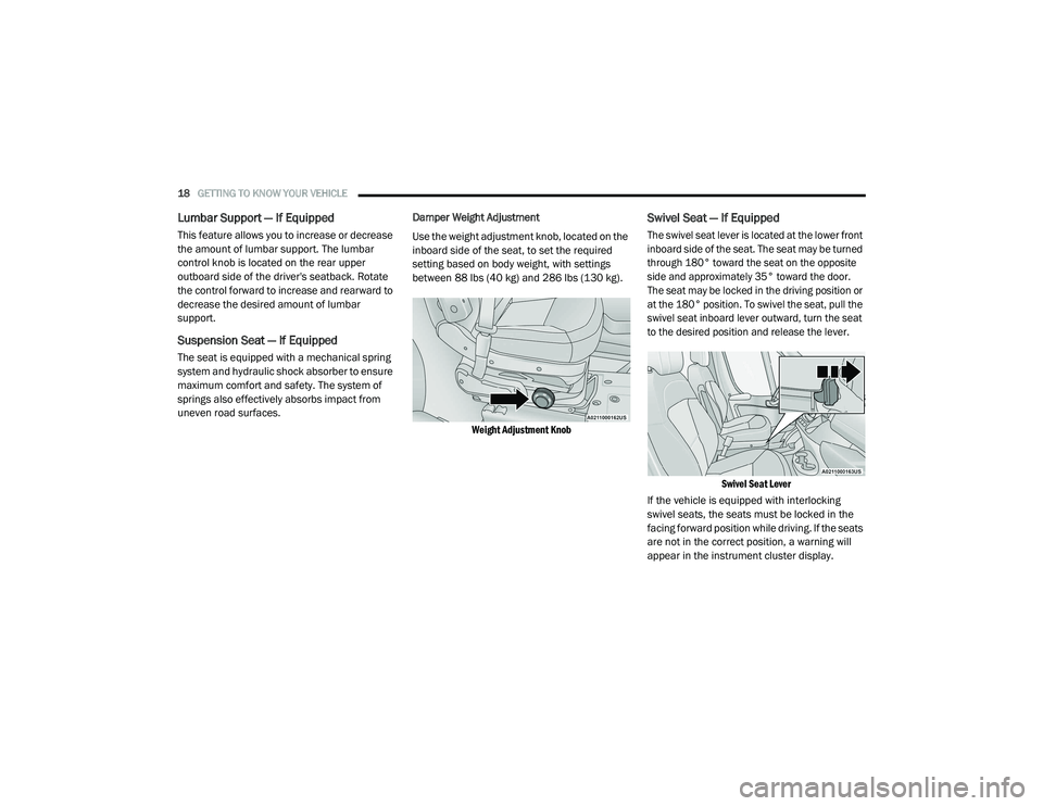
Use the weight adjustment knob, located on the
inboard side of the seat, to set the required
setting based on body weight, with settings
between 88 lbs (40 kg) and 286 lbs (130 kg).
Weight Adjustment Knob
Swivel Seat — If Equipped
The swivel seat lever is located at the lower front
inboard side of the seat. The seat may be turned
through 180° toward the seat on the opposite
side and approximately 35° toward the door.
The seat may be locked in the driving position or
at the 180° position. To swivel the seat, pull the
swivel seat inboard lever outward, turn the seat
to the desired position and release the lever.
Swivel Seat Lever
If the vehicle is equipped with interlocking
swivel seats, the seats must be locked in the
facing forward position while driving. If the seats
are not in the correct position, a warning will
appear in the instrument cluster display.
21_VF_OM_EN_USC_t.book Page 18
Page 21 of 288

GETTING TO KNOW YOUR VEHICLE19
If the driver or the passenger seats are not locked
in the facing forward position before the first
vehicle movement, shifting out of park is not
allowed until the seats are both locked in the
facing forward position. When the seats are not in
the right position and the first vehicle movement
after ignition START is attempted, a chime and a
message will appear in the instrument cluster
display. Rotate and lock the swivel seats in the
correct position before trying again.
If the driver or the passenger seats are not
locked in the facing forward position during
movement of the vehicle, a message will appear
in the instrument cluster display and an
intermittent chime will sound until key-off or
until the swivel seats are locked in the facing
forward position. Stop and move the swivel
seats in the correct position before proceeding.
If a fault is present in the system and it is not
possible to check the correct position of the
swivel seats, a message and the generic
warning light appears in the instrument cluster
display to inform about the failure. In these
conditions, check the status of the swivel seats
and do not drive the vehicle until the swivel
seats are locked in the facing forward position.HEATED SEATS — IF EQUIPPED
On some models, the front driver and
passenger seats may be equipped with heaters
in both the seat cushions and seatbacks. The
controls for the front heated seats are located
on the lower outboard side of the seat.
Heated Seat Switch
Push the switch once to turn on the heated
seats. Push the switch a second time to shut the
heating elements off. NOTE:
Once a heat setting is selected, heat will be felt
within two to five minutes.
WARNING!
Persons who are unable to feel pain to the
skin because of advanced age, chronic
illness, diabetes, spinal cord injury, medica
-
tion, alcohol use, exhaustion or other phys -
ical condition must exercise care when
using the seat heater. It may cause burns
even at low temperatures, especially if
used for long periods of time.
Do not place anything on the seat or seat -
back that insulates against heat, such as a
blanket or cushion. This may cause the seat
heater to overheat. Sitting in a seat that has
been overheated could cause serious
burns due to the increased surface
temperature of the seat.
2
21_VF_OM_EN_USC_t.book Page 19
Page 26 of 288

24GETTING TO KNOW YOUR VEHICLE
If it becomes difficult to see clearly in the display,
the camera may need to be cleaned. If snow, ice,
mud, or any foreign substance builds up on the
camera lens, clean the lens, rinse with water,
and dry with a soft cloth. Do not cover the lens.
Camera Location
OUTSIDE MIRRORS
To receive maximum benefit, adjust the outside
mirror(s) to center on the adjacent lane of traffic
with a slight overlap of the view obtained on the
inside mirror.
Outside Mirrors Folding Feature
All outside mirrors are hinged and may be
folded forward or rearward to avoid damage.
The hinges have three detent positions:
Full forward position
Full rearward position
Normal position
POWER MIRRORS — IF EQUIPPED
The power mirror controls are located on the
driver’s side door trim panel.
Power Mirror Controls
To adjust a mirror, turn the control knob toward
the left upper, left lower, right upper or right
lower mirror positions indicated by one of the
four arrows on the switch. Tilt the control knob
in the direction you want the mirror to move.
When you are finished adjusting the mirror, turn
the control to the center position “O” to prevent
accidentally moving a mirror.
NOTE:
If your vehicle is equipped with a power blind
spot mirror, you can adjust them when the
control knob is positioned to the lower arrows.
WARNING!
Vehicles and other objects seen in an outside
convex mirror will look smaller and farther
away than they really are. Relying too much
on side convex mirrors could cause you to
collide with another vehicle or other object.
Use your inside mirror when judging the size
or distance of a vehicle seen in a side convex
mirror.
21_VF_OM_EN_USC_t.book Page 24
Page 29 of 288

GETTING TO KNOW YOUR VEHICLE27
FOLLOW ME HOME/HEADLIGHT DELAY
When this feature is selected, the driver can
choose to have the headlights remain on for a
preset period of time after the engine is turned
off.
Activation
Remove the key or turn the ignition to the STOP
(OFF/LOCK) position, and pull the multifunction
lever toward the steering wheel within two
minutes. Each time the lever is pulled, the
activation of the lights will be extended by
30 seconds. The activation of the lights can be
extended to a maximum of 210 seconds.
The indicator light on the instrument panel will
light up and the corresponding message will
appear in the instrument cluster display for as
long as the function is activated. The indicator
light comes on when the lever is operated and
stays on until the function is automatically
deactivated. Each movement of the lever only
increases the amount of time the lights stay on.
Deactivation
Pull the multifunction lever toward the steering
wheel and hold it for more than two seconds.
FOG LIGHTS — IF EQUIPPED
The fog light switch is located on the center
stack of the instrument panel, just below the
climate controls.
Push the switch once to turn the fog
lights on. Push the switch a second
time to turn the fog lights off.
NOTE:
If the vehicle’s ignition is turned off, the fog
lights will also turn off.
TURN SIGNALS
Move the multifunction lever up or down and
the arrows on each side of the instrument
cluster will flash to show proper operation of the
turn signals.
NOTE:
If either light remains on and does not flash, or
there is a very fast flash rate, check for a defec -
tive outside light bulb.
LANE CHANGE ASSIST
Lightly push the multifunction lever up or down,
without moving beyond the detent, and the turn
signal will flash five times then automatically
turn off.
BATTERY SAVER
To protect the life of your vehicle’s battery,
when the ignition is OFF and any door is left ajar
for 15 minutes, the interior lights will
automatically turn off.
NOTE:
Battery saver mode is cancelled if the ignition is
placed in the MAR (ACC/ON/RUN) position.
2
21_VF_OM_EN_USC_t.book Page 27
Page 31 of 288

GETTING TO KNOW YOUR VEHICLE29
Side Cargo Lamp Location
The Rear and Side Cargo Lamps can be set to
three different positions by pushing the lens to
the right, left, or center positions.
Push the lens to the right from its center posi -
tion and the lamp is always off.
Leave the lens in the center position, and the
lamp is turned on and off when the sliding
doors or rear doors are opened or closed.
Push the lens to the left from its center posi -
tion and the lamp is always on.
Your vehicle may also be equipped with a cargo
lamp on the center of the ceiling of the cargo
area.
Ceiling Cargo Lamp
The Ceiling Cargo Lamp can be set to three
different positions (off/left position, center
position, on/right position).
Push the switch to the left from its center
position and the lamp is always off.
Leave the switch in the center position, and
the lamp is turned on and off when the sliding
doors or rear doors are opened or closed.
Push the switch to the right from its center
position and the lamp is always on.
NOTE:
If the ignition is placed in the OFF position, the
lamp will stay on for about 15 minutes and then
time out.
Dimmer Controls
The dimmer controls are located on the left side
of the instrument panel below the instrument
cluster display.
Dimmer Controls
Pushing the up or down arrow will increase or
decrease the brightness of the instrument
panel lights, cupholder lights, and footwell
lights, as long as the headlights are turned on.
Ambient Light
The vehicle is equipped with ambient light on
the dome lamp. The ambient light will be on all
the time, with the option of dimming it with the
dimmer controls as long as the headlights are
turned on.
2
21_VF_OM_EN_USC_t.book Page 29
Page 33 of 288

GETTING TO KNOW YOUR VEHICLE31
Mist
Use the Mist feature when weather conditions
make occasional usage of the wipers
necessary. Push the lever upward to the MIST
position and release for a single wiping cycle.
NOTE:
The mist feature does not activate the washer
pump; therefore, no washer fluid will be sprayed
on the windshield. The wash function must be
used in order to spray the windshield with
washer fluid.
For information on wiper care and replacement,
see Úpage 221.
CLIMATE CONTROLS
The Climate Control system allows you to
regulate the temperature, air flow, and direction
of air circulating throughout the vehicle. The
controls are located on the touchscreen (if
equipped) and on the instrument panel below
the radio.
MANUAL CLIMATE CONTROL
D
ESCRIPTIONS AND FUNCTIONS
Uconnect 3 With 5-inch Display With Manual Climate
Controls
The Manual Temperature Controls consist of a
series of three outer rotary dials (blower speed,
temperature and mode) and three inner push
buttons (Recirculation, A/C, Rear Window
Defroster).
A/C Button — If Equipped
Push the A/C button to engage the Air
Conditioning (A/C). The A/C indicator
illuminates when A/C is on.
NOTE:
For Manual Climate Controls, if the system is
in Mix, Floor or Defrost Mode, the A/C can be
turned off, but the A/C system shall remain
active to prevent fogging of the windows.
If fog or mist appears on the windshield or
side glass, select Defrost mode, and increase
blower speed if needed.
If your air conditioning performance seems
lower than expected, check the front of the
A/C condenser (located in front of the radi -
ator), for an accumulation of dirt or insects.
Clean with a gentle water spray from the front
of the radiator and through the condenser.
WARNING!
Sudden loss of visibility through the
windshield could lead to a collision. You might
not see other vehicles or other obstacles. To
avoid sudden icing of the windshield during
freezing weather, warm the windshield with
the defroster before and during windshield
washer use.
2
21_VF_OM_EN_USC_t.book Page 31
Page 45 of 288

GETTING TO KNOW YOUR INSTRUMENT PANEL43
INSTRUMENT CLUSTER DESCRIPTIONS
1. Speedometer
Indicates vehicle speed.
2. Instrument Cluster Display
When the appropriate conditions exist,
this display shows instrument cluster
display messages Ú page 44.
Odometer/Trip Odometer Display Area
US Federal regulations require that upon
transfer of vehicle ownership, the seller
certify to the purchaser the correct mileage
that the vehicle has been driven. If your
odometer needs to be repaired or serviced,
the repair technician should leave the odom -
eter reading the same as it was before the
repair or service. If the technician cannot do
so, then the odometer must be set at zero,
and a sticker must be placed in the door
jamb stating what the mileage was before the
repair or service. It is a good idea for you to
make a record of the odometer reading before the repair/service, so that you can be
sure that it is properly reset, or that the door
jamb sticker is accurate if the odometer must
be reset at zero.
Gear Selector Status (PRND)
The gear selector status “P,R,N,D,1,2,3,4,5,
6” are displayed indicating the gear selector
position. Telltales “1,2,3,4,5,6” indicate the
manual mode has been engaged and the
gear selected is displayed Ú page 60.
Instrument Cluster Display Location
3. Tachometer
This gauge measures engine revolutions
per minute (RPM x 1000). Before the
pointer reaches the red area, ease up on
the accelerator to prevent engine
damage.
4. Temperature Gauge
The temperature gauge shows engine
coolant temperature. Any reading within
the normal range indicates that the engine
cooling system is operating satisfactorily.
The pointer will likely indicate a higher
temperature when driving in hot weather
or up mountain grades. It should not be
allowed to exceed the upper limits of the
normal operating range.
WARNING!
A hot engine cooling system is dangerous. You or
others could be badly burned by steam or boiling
coolant. You may want to call an authorized
dealer for service if your vehicle overheats.
3
21_VF_OM_EN_USC_t.book Page 43
Page 46 of 288

44GETTING TO KNOW YOUR INSTRUMENT PANEL
5. Fuel Gauge
The pointer shows the level of fuel in the
fuel tank when the ignition switch is in
the ON/RUN position.
The fuel pump symbol points
to the side of the vehicle where
the fuel door is located
Ú page 75.
INSTRUMENT CLUSTER DISPLAY
Your vehicle will be equipped with an
instrument cluster display, which offers useful
information to the driver. With the ignition in the
STOP (OFF/LOCK) mode, opening/closing of a
door will activate the display for viewing, and
display the total miles, or kilometers, in the
odometer. Your instrument cluster display is
designed to display important information
about your vehicle’s systems and features.
Using a driver interactive display located on the
instrument panel, your instrument cluster
display can show you how systems are working
and give you warnings when they are not. The
steering wheel mounted controls allow you to
scroll through the main menus and submenus.
You can access the specific information you
want and make selections and adjustments.
LOCATION AND CONTROLS
The instrument cluster display features a driver
interactive display that is located in the
instrument cluster.
Instrument Cluster Display
This system allows the driver to select a variety
of useful information by pushing the switches
mounted on the instrument panel. Examples of
menu items are:
Speed Beep
Buzzer Volume
Seat Belt Buzzer
Exit Menu
CAUTION!
Driving with a hot engine cooling system could
damage your vehicle. If the temperature gauge
reads “H,” pull over and stop the vehicle. Idle
the vehicle with the air conditioner turned off
until the pointer drops back into the normal
range. If the pointer remains on the “H,” turn
the engine off immediately and call an
authorized dealer for service.
21_VF_OM_EN_USC_t.book Page 44
Page 47 of 288

GETTING TO KNOW YOUR INSTRUMENT PANEL45
If equipped with a Uconnect system, some
customer programmable features will display in
the radio Úpage 89.
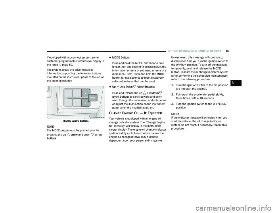
The system allows the driver to select
information by pushing the following buttons
mounted on the instrument panel to the left of
the steering column:
Display Control Buttons
NOTE:
The MODE button must be pushed prior to
pressing the up arrow and down arrow
buttons .MODE Button:
Push and hold the MODE button for a time
longer than one second to access/select the
information screens or submenu screens of a
main menu item. Push and hold the MODE
button for two seconds to reset displayed/
selected features that can be reset.
Up And Down Arrow Buttons:
Push and release the up and down
arrow buttons to scroll upward and down -
ward through the main menu and submenus
or adjust the illumination on the instrument
panel when the headlights are on.
CHANGE ENGINE OIL — IF EQUIPPED
Your vehicle is equipped with an engine oil
change indicator system. The “Change Engine
Oil” message will display in the instrument
cluster display. The engine oil change indicator
system is duty cycle based, which means the
engine oil change interval may fluctuate,
dependent upon your personal driving style. Unless reset, this message will continue to
display each time you turn the ignition switch to
the ON/RUN position. To turn off the message
temporarily, push and release the
MODE
button . To reset the oil change indicator system
(after performing the scheduled maintenance),
refer to the following procedure.
1. Turn the ignition switch to the ON position (do not start the engine).
2. Fully push the accelerator pedal slowly, three times, within 10 seconds.
3. Turn the ignition switch to the OFF/LOCK position.
NOTE:
If the indicator message illuminates when you
start the vehicle, the oil change indicator
system did not reset. If necessary, repeat this
procedure.
3
21_VF_OM_EN_USC_t.book Page 45