stop start RAM PROMASTER 2021 Owner's Manual
[x] Cancel search | Manufacturer: RAM, Model Year: 2021, Model line: PROMASTER, Model: RAM PROMASTER 2021Pages: 288, PDF Size: 15.22 MB
Page 103 of 288
MULTIMEDIA101
UCONNECT MODES
RADIO MODE
Operating Radio Mode
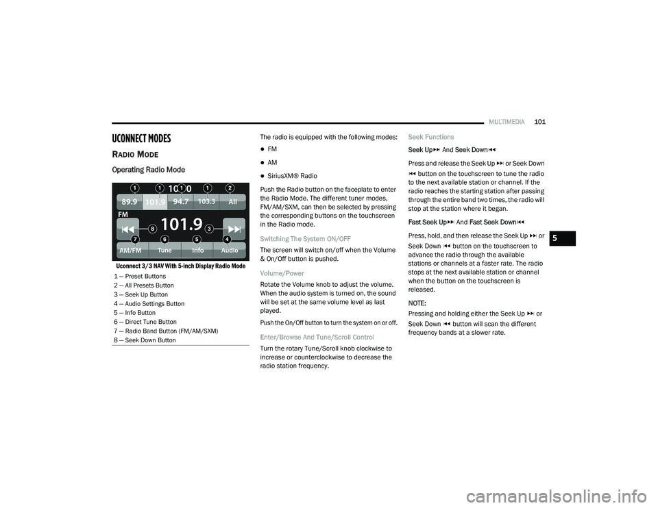
Uconnect 3/3 NAV With 5-inch Display Radio Mode
The radio is equipped with the following modes:
FM
AM
SiriusXM® Radio
Push the Radio button on the faceplate to enter
the Radio Mode. The different tuner modes,
FM/AM/SXM, can then be selected by pressing
the corresponding buttons on the touchscreen
in the Radio mode.
Switching The System ON/OFF
The screen will switch on/off when the Volume
& On/Off button is pushed.
Volume/Power
Rotate the Volume knob to adjust the volume.
When the audio system is turned on, the sound
will be set at the same volume level as last
played.
Push the On/Off button to turn the system on or off.
Enter/Browse And Tune/Scroll Control
Turn the rotary Tune/Scroll knob clockwise to
increase or counterclockwise to decrease the
radio station frequency. Seek Functions
Seek Up
And Seek Down
Press and release the Seek Up or Seek Down button on the touchscreen to tune the radio
to the next available station or channel. If the
radio reaches the starting station after passing
through the entire band two times, the radio will
stop at the station where it began.
Fast Seek Up And Fast Seek Down
Press, hold, and then release the Seek Up or
Seek Down button on the touchscreen to
advance the radio through the available
stations or channels at a faster rate. The radio
stops at the next available station or channel
when the button on the touchscreen is
released.
NOTE:
Pressing and holding either the Seek Up or
Seek Down button will scan the different
frequency bands at a slower rate.
1 — Preset Buttons
2 — All Presets Button
3 — Seek Up Button
4 — Audio Settings Button
5 — Info Button
6 — Direct Tune Button
7 — Radio Band Button (FM/AM/SXM)
8 — Seek Down Button
5
21_VF_OM_EN_USC_t.book Page 101
Page 131 of 288
MULTIMEDIA129
Planning A Route Using My Places
1. Select the Main Menu button.
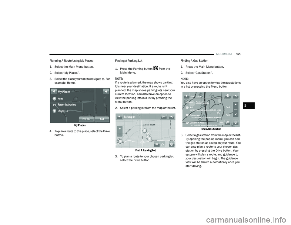
2. Select “My Places”.
3. Select the place you want to navigate to. For
example: Home.
My Places
4. To plan a route to this place, select the Drive button. Finding A Parking Lot
1. Press the Parking button from the
Main Menu.
NOTE:
If a route is planned, the map shows parking
lots near your destination. If a route isn’t
planned, the map shows parking lots near your
current location. You also have an option to
view the parking lots in a list by pressing the
Menu button.
2. Select a parking lot from the map or the list.
Find A Parking Lot
3. To plan a route to your chosen parking lot, select the Drive button. Finding A Gas Station
1. Press the Main Menu button.
2. Select “Gas Station”.
NOTE:
You also have an option to view the gas stations
in a list by pressing the Menu button.
Find A Gas Station
3. Select a gas station from the map or the list. By opening the pop-up menu, you can add
the gas station as a stop on your route. You
can also plan a route to your chosen gas
station by pressing the Drive button. Your
system will plan a route, and guidance to
your destination will begin. The guidance
view will be shown automatically once you
start driving.
5
21_VF_OM_EN_USC_t.book Page 129
Page 142 of 288
140MULTIMEDIA
Arrival Information
In the settings menu, select “Arrival
Information” to change the following settings:
Show Remaining Distance : Select this setting
to show the remaining distance left to travel
in the arrival information panel during navi -
gation.
Show Remaining Time : Select this setting to
show the remaining time left to travel in the
arrival information panel during navigation.
Switch Between Distance And Time Automat -
ically : Select this setting to control the auto -
matic switching between remaining distance
and remaining time in the arrival information
panel.
Show On Route
In the settings menu, select “Show On Route” to
see any of the following options in the route bar:
Parking : Select this setting to see parking lots
on your route.
Gas Stations: Select this setting to see gas
stations on your route.
Stops : Select this setting to see stops on your
route. Show Previews Of Highway Exits
Select this setting to control the full screen
preview when you approach highway exits.
Automatic Map View Switching
Automatic changing of views is on by default.
For example, when an alternative route is being
suggested, the map will automatically switch to
map view, and when you start driving, your map
will automatically switch to guidance view. You
can turn this feature off by selecting “Automatic
Map View Switching” in the settings.
Automatic Zoom
Select this setting to control the full screen
preview when you approach highway exits.
Guidance View Style
Select this setting to choose between 3D and
2D versions of the guidance view. Both the 2D
and 3D guidance views move in your direction
of travel.
In 3D guidance view, you can choose to use the
3D car icon or an arrowhead as the current
location indicator. By default, the 3D guidance
view shows the 3D car icon.
Voices Setting
Select this setting to change how instructions
are read out loud Ú
page 139.
Route Planning
Select this setting to control how your system
plans routes. The following options are
available:
Always Take the Fastest Route
You can choose whether you would like the
navigation system to always default to the
fastest route.
Ask Me So I Can Choose
You can choose whether you would like the
navigation system to allow you to pick the
route to the destination.
Don’t Ask me
You can choose whether you would like the
navigation system to select the route to the
destination.
21_VF_OM_EN_USC_t.book Page 140
Page 144 of 288
142MULTIMEDIA
Points Of Interest
About Points Of Interest
Points Of Interest (POI) are useful places on the
map.
Here are some examples:
Restaurants
Hotels
Museums
Parking lots
Gas stations
Emergency Services
Using POIs To Plan A Route
When you plan a route, you can use a POI for the
destination or as a stop along the route. Using Search
1. Select “Search” on the Main Menu to begin
a search. The search screen will open,
displaying the keyboard. Enter the name of
your desired destination. Your search
results will be displayed in two lists.
Addresses and city matches are shown in
the list called “Addresses.” POIs, types of
POIs, and Places are shown in the list
called “Points of Interest.” You can also
select a POI category to only see POI
search results from that category.
2. Select the desired POI. The location will appear on the map. From here, you can
save the POI to “My Places,” use this POI as
a starting point, begin navigation to this
destination, or view more details about this
POI. By pressing “More Information,” you
can view the phone number and full
address of the POI.
3. If a route is already planned, you can add the location to your current route. To plan a
route to this destination, press the Drive
button on the touchscreen. NOTE:
Your navigation system will calculate a route,
and guidance to your destination will begin.
Guidance view will begin as soon as you start
driving.
My Places
About My Places
My Places provides an easy way to
select a location without the need to
enter the address or search for the
location. You can use My Places to
create a collection of useful or favorite
addresses.
The following items are always in My Places:
Home : Your home location can be your home
address or somewhere you often visit. This
feature provides an easy way to navigate
there.
Recent Destinations: Select this button to
select your destination from a list of locations
you have recently navigated to.
21_VF_OM_EN_USC_t.book Page 142
Page 152 of 288
150SAFETY
ELECTRONIC BRAKE CONTROL (EBC)
S
YSTEM
Your vehicle is equipped with an advanced
Electronic Brake Control (EBC) system that
includes the Brake Assist System (BAS) and
Electronic Stability Control (ESC), Hill Start
Assist (HSA), Traction Control System (TCS), and
Trailer Sway Control (TSC). These systems
complement the Anti-Lock Brake System (ABS)
by optimizing the vehicle braking capability
during emergency braking maneuvers.
Brake Assist System (BAS)
The BAS is designed to optimize the vehicle’s
braking capability during emergency braking
maneuvers. The system detects an emergency
braking situation by sensing the rate and
amount of brake application and then applies
optimum pressure to the brakes. This can help
reduce braking distances. The BAS
complements the Anti-Lock Brake System
(ABS). Applying the brakes very quickly results
in the best BAS assistance. To receive the
benefit of the system, you must apply
continuous braking pressure during the
stopping sequence (do not “pump” the brakes). Do not reduce brake pedal pressure unless
braking is no longer desired. Once the brake
pedal is released, the BAS is deactivated.
Crosswind Assist (CWA)
CWA helps keep your vehicle from drifting out of
its lane due to unexpected crosswinds by
means of targeted braking of individual wheels.
The system will provide automatic stability
assistance to counteract the effect of strong
side wind. If a strong lateral wind is detected,
front and rear brakes on the affected side are applied, creating a steering effect that mitigates
the cross wind influence. During system
intervention, the driver should perceive the
natural stable handling feel of the vehicle.
Crosswind Assist will activate automatically
when the vehicle reaches speeds above
approximately 43 mph (70 km/h). When the
system is activated, the ESC Warning Light in
the instrument cluster will blink to warn the
driver.
Electronic Stability Control (ESC)
ESC enhances directional control and stability
of the vehicle under various driving conditions.
ESC corrects for over/under steering of the
vehicle by applying the brake of the appropriate
wheel(s) to counteract the above conditions.
Engine power may also be reduced to help the
vehicle maintain the desired path.
Oversteer – when the vehicle is turning more
than appropriate for the steering wheel
position.
Understeer – when the vehicle is turning less
than appropriate for the steering wheel
position.
WARNING!
The Brake Assist System (BAS) cannot
prevent the natural laws of physics from
acting on the vehicle, nor can it increase the
traction afforded by prevailing road
conditions. BAS cannot prevent collisions,
including those resulting from excessive
speed in turns, driving on very slippery
surfaces, or hydroplaning. The capabilities of
a BAS-equipped vehicle must never be
exploited in a reckless or dangerous manner,
which could jeopardize the user's safety or
the safety of others.
21_VF_OM_EN_USC_t.book Page 150
Page 155 of 288
SAFETY153
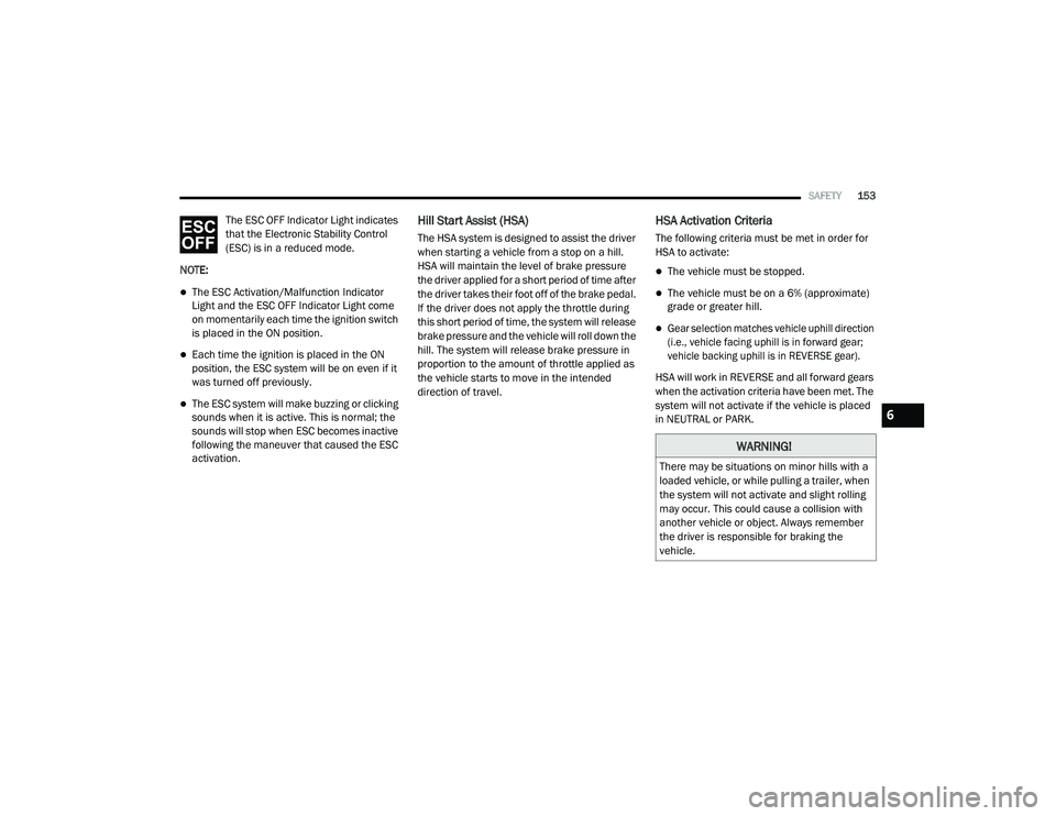
The ESC OFF Indicator Light indicates
that the Electronic Stability Control
(ESC) is in a reduced mode.
NOTE:
The ESC Activation/Malfunction Indicator
Light and the ESC OFF Indicator Light come
on momentarily each time the ignition switch
is placed in the ON position.
Each time the ignition is placed in the ON
position, the ESC system will be on even if it
was turned off previously.
The ESC system will make buzzing or clicking
sounds when it is active. This is normal; the
sounds will stop when ESC becomes inactive
following the maneuver that caused the ESC
activation.
Hill Start Assist (HSA)
The HSA system is designed to assist the driver
when starting a vehicle from a stop on a hill.
HSA will maintain the level of brake pressure
the driver applied for a short period of time after
the driver takes their foot off of the brake pedal.
If the driver does not apply the throttle during
this short period of time, the system will release
brake pressure and the vehicle will roll down the
hill. The system will release brake pressure in
proportion to the amount of throttle applied as
the vehicle starts to move in the intended
direction of travel.
HSA Activation Criteria
The following criteria must be met in order for
HSA to activate:
The vehicle must be stopped.
The vehicle must be on a 6% (approximate)
grade or greater hill.
Gear selection matches vehicle uphill direction
(i.e., vehicle facing uphill is in forward gear;
vehicle backing uphill is in REVERSE gear).
HSA will work in REVERSE and all forward gears
when the activation criteria have been met. The
system will not activate if the vehicle is placed
in NEUTRAL or PARK.
WARNING!
There may be situations on minor hills with a
loaded vehicle, or while pulling a trailer, when
the system will not activate and slight rolling
may occur. This could cause a collision with
another vehicle or object. Always remember
the driver is responsible for braking the
vehicle.
6
21_VF_OM_EN_USC_t.book Page 153
Page 156 of 288
154SAFETY
Towing With HSA
HSA will also provide assistance to mitigate roll
back while towing a trailer.
Traction Control System (TCS)
TCS monitors the amount of wheel spin of each
of the driven wheels. If wheel spin is detected,
brake pressure is applied to the slipping
wheel(s) and engine power is reduced, to
provide enhanced acceleration and stability. A
feature of the TCS, Brake Limited Differential
(BLD), functions similarly to a limited slip
differential and controls the wheel spin across a
driven axle. If one wheel on a driven axle is
spinning faster than the other, the system will
apply the brake of the spinning wheel. This will
allow more engine torque to be applied to the
wheel that is not spinning. This feature remains
active even if the ESC is in the “Partial Off”
mode.
The ESC Activation/Malfunction Indicator Light
(in the instrument cluster) will start to flash as
soon as the tires lose traction and the wheels
begin to spin. This indicates that the TCS is
active. If the indicator light flashes during
acceleration, ease up on the accelerator and
apply as little throttle as possible. Be sure to
adapt your speed and driving to the prevailing
road conditions, and do not switch off the ESC
or TCS.
Trailer Sway Control (TSC) — If Equipped
TSC uses sensors in the vehicle to recognize an
excessively swaying trailer and will take the
appropriate actions to attempt to stop the sway.
The system may reduce engine power and apply
the brake of the appropriate wheel(s) to
counteract the sway of the trailer.
WARNING!
If you use a trailer brake controller with your
trailer, the trailer brakes may be activated
and deactivated with the brake switch. If
so, there may not be enough brake pres -
sure to hold both the vehicle and the trailer
on a hill when the brake pedal is released.
In order to avoid rolling down an incline
while resuming acceleration, manually acti -
vate the trailer brake or apply more vehicle
brake pressure prior to releasing the brake
pedal.
HSA is not a parking brake. Always apply
the parking brake fully when exiting your
vehicle. Also, be certain to place the trans -
mission in PARK.
Failure to follow these warnings can result
in a collision or serious personal injury.
WARNING!
The TCS cannot prevent the natural laws of
physics from acting on the vehicle, nor can
it increase the traction afforded.
The TCS cannot prevent collisions,
including those resulting from excessive
speed in turns, or hydroplaning.
The capabilities of a TCS-equipped vehicle
must never be exploited in a reckless or
dangerous manner, which could jeopardize
the user's safety or the safety of others.
21_VF_OM_EN_USC_t.book Page 154
Page 157 of 288
SAFETY155
NOTE:
TSC cannot stop all trailers from swaying.
Always use caution when towing a trailer and
follow the trailer tongue weight recommenda -
tions Ú page 78.
When TSC is functioning, the ESC Activation/
Malfunction Indicator Light will flash, the engine
power may be reduced, and you may feel the
brakes being applied to individual wheels to
attempt to stop the trailer from swaying. TSC is
disabled when the ESC system is in the “Partial
Off” mode.AUXILIARY DRIVING SYSTEMS
BLIND SPOT MONITORING (BS M) — IF
E
QUIPPED
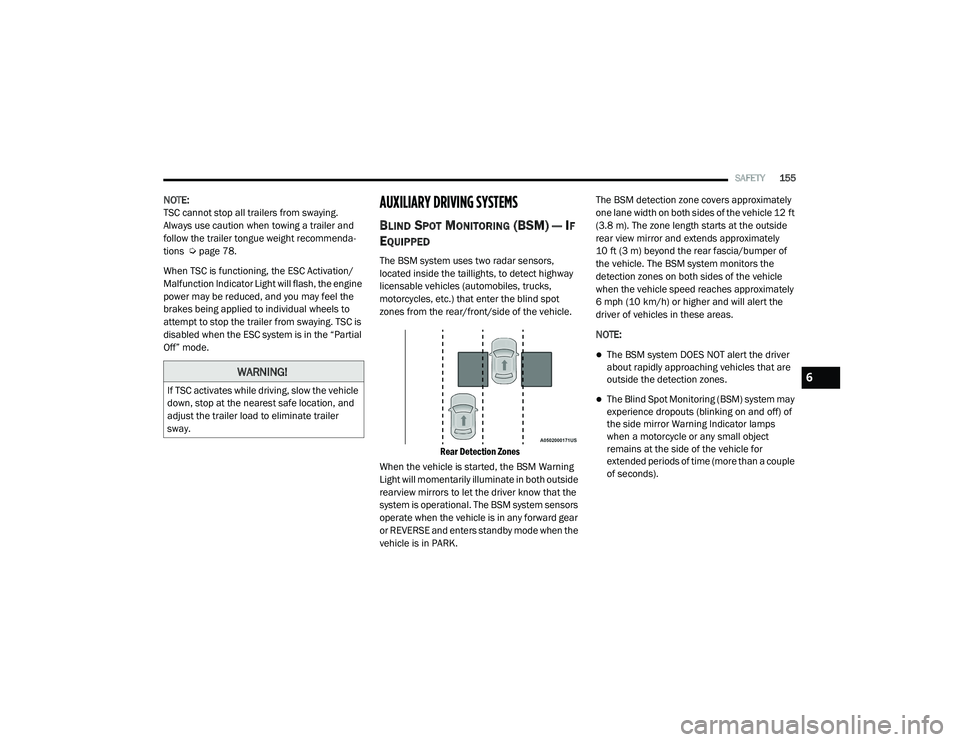
The BSM system uses two radar sensors,
located inside the taillights, to detect highway
licensable vehicles (automobiles, trucks,
motorcycles, etc.) that enter the blind spot
zones from the rear/front/side of the vehicle.
Rear Detection Zones
When the vehicle is started, the BSM Warning
Light will momentarily illuminate in both outside
rearview mirrors to let the driver know that the
system is operational. The BSM system sensors
operate when the vehicle is in any forward gear
or REVERSE and enters standby mode when the
vehicle is in PARK. The BSM detection zone covers approximately
one lane width on both sides of the vehicle 12 ft
(3.8 m). The zone length starts at the outside
rear view mirror and extends approximately
10 ft (3 m) beyond the rear fascia/bumper of
the vehicle. The BSM system monitors the
detection zones on both sides of the vehicle
when the vehicle speed reaches approximately
6 mph (10 km/h) or higher and will alert the
driver of vehicles in these areas.
NOTE:
The BSM system DOES NOT alert the driver
about rapidly approaching vehicles that are
outside the detection zones.
The Blind Spot Monitoring (BSM) system may
experience dropouts (blinking on and off) of
the side mirror Warning Indicator lamps
when a motorcycle or any small object
remains at the side of the vehicle for
extended periods of time (more than a couple
of seconds).
WARNING!
If TSC activates while driving, slow the vehicle
down, stop at the nearest safe location, and
adjust the trailer load to eliminate trailer
sway.
6
21_VF_OM_EN_USC_t.book Page 155
Page 161 of 288
SAFETY159
NOTE:
Whenever an audible alert is requested by the
BSM system, the radio is also muted.
When the system is in RCP, the system shall
respond with both visual and audible alerts
when a detected object is present. Whenever
an audible alert is requested, the radio is also
muted. Turn/hazard signal status is ignored;
the RCP state always requests the chime.
Blind Spot Alert Off
When the BSM system is turned off there will be
no visual or audible alerts from either the BSM
or RCP systems.
NOTE:
The BSM system will store the current operating
mode when the vehicle is shut off. Each time
the vehicle is started the previously stored
mode will be recalled and used.
FORWARD COLLISION WARNING (FCW)
W
ITH MITIGATION — IF EQUIPPED
The FCW with Mitigation system provides the
driver with audible warnings, visual warnings
(within the instrument cluster display), and may
apply a brake jerk to warn the driver when it
detects a potential frontal collision. The warnings and limited braking are intended
to provide the driver with enough time to react,
avoid or mitigate the potential collision.
NOTE:
FCW monitors the information from the forward
looking sensors as well as the Electronic Brake
Controller (EBC), to calculate the probability of a
forward collision. When the system determines
that a forward collision is probable, the driver
will be provided with audible and visual warn-
ings as well as a possible brake jerk warning.
If the driver does not take action based upon
these progressive warnings, then the system
will provide a limited level of active braking to
help slow the vehicle and mitigate the potential
forward collision. If the driver reacts to the warn
-
ings by braking and the system determines that
the driver intends to avoid the collision by
braking but has not applied sufficient brake
force, the system will compensate and provide
additional brake force as required.
If a FCW with Mitigation event begins at a speed
below 26 mph (42 km/h), the system may
provide the maximum braking possible to miti -
gate the potential forward collision. Vehicles
With Automatic Transmission: After the end of the intervention of automatic braking, the trans
-
mission may remain in last gear stored — there -
fore the vehicle could lurch forward, once the
brakes release a few seconds later. If the
Forward Collision Warning with Mitigation event
stops the vehicle completely, the system will
hold the vehicle at standstill for two seconds
and then release the brakes.
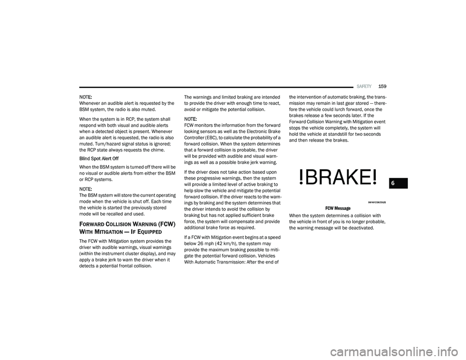
FCW Message
When the system determines a collision with
the vehicle in front of you is no longer probable,
the warning message will be deactivated.
6
21_VF_OM_EN_USC_t.book Page 159
Page 168 of 288
166SAFETY
Enhanced Seat Belt Use Reminder System
(BeltAlert)
Driver and Passenger BeltAlert — If Equipped
BeltAlert is a feature intended to remind the
driver and outboard front seat passenger (if
equipped with outboard front passenger seat
BeltAlert) to buckle their seat belts. The BeltAlert
feature is active whenever the ignition switch is in
the AVV/START or MAR/RUN position.
Initial Indication
If the driver is unbuckled when the ignition
switch is first in the AVV/START or MAR/RUN
position, a chime will signal for a few seconds. If
the driver or outboard front seat passenger (if
equipped with outboard front passenger seat
BeltAlert) is unbuckled when the ignition switch
is first in the AVV/START or MAR/RUN position
the Seat Belt Reminder Light will turn on and
remain on until both outboard front seat belts
are buckled. The outboard front passenger seat
BeltAlert is not active when an outboard front
passenger seat is unoccupied.
BeltAlert Warning Sequence
The BeltAlert warning sequence is activated
when the vehicle is moving above a specified
vehicle speed range and the driver or outboard front seat passenger is unbuckled (if equipped
with outboard front passenger seat BeltAlert)
(the outboard front passenger seat BeltAlert is
not active when the outboard front passenger
seat is unoccupied). The BeltAlert warning
sequence starts by blinking the Seat Belt
Reminder Light and sounding an intermittent
chime. Once the BeltAlert warning sequence
has completed, the Seat Belt Reminder Light
will remain on until the seat belts are buckled.
The BeltAlert warning sequence may repeat
based on vehicle speed until the driver and
occupied outboard front seat passenger seat
belts are buckled. The driver should instruct all
occupants to buckle their seat belts.
Change of Status
If the driver or outboard front seat passenger (if
equipped with outboard front passenger seat
BeltAlert) unbuckles their seat belt while the
vehicle is traveling, the BeltAlert warning
sequence will begin until the seat belts are
buckled again.
The outboard front passenger seat BeltAlert is not
active when the outboard front passenger seat is
unoccupied. BeltAlert may be triggered when an
animal or other items are placed on the outboard
front passenger seat or when the seat is folded
flat (if equipped). It is recommended that pets be
restrained in the rear seat (if equipped) in pet
harnesses or pet carriers that are secured by seat
belts, and cargo is properly stowed.
BeltAlert can be activated or deactivated by an
authorized dealer. FCA US LLC does not
recommend deactivating BeltAlert.
NOTE:
If BeltAlert has been deactivated and the driver
or outboard front seat passenger (if equipped
with outboard front passenger seat BeltAlert) is
unbuckled the Seat Belt Reminder Light will turn
on and remain on until the driver and outboard
front seat passenger seat belts are buckled.
Lap/Shoulder Belts
All seating positions in your vehicle are
equipped with lap/shoulder belts.
The seat belt webbing retractor will lock only
during very sudden stops or collisions. This
feature allows the shoulder part of the seat belt
to move freely with you under normal
conditions. However, in a collision the seat belt
will lock and reduce your risk of striking the
inside of the vehicle or being thrown out of the
vehicle.
21_VF_OM_EN_USC_t.book Page 166