tow RAM PROMASTER 2021 Owner's Guide
[x] Cancel search | Manufacturer: RAM, Model Year: 2021, Model line: PROMASTER, Model: RAM PROMASTER 2021Pages: 288, PDF Size: 15.22 MB
Page 86 of 288

84STARTING AND OPERATING
Seven-Pin Connector
TOWING TIPS
Before towing, practice turning, stopping, and
backing up the trailer in an area located away
from heavy traffic.
Automatic Transmission
The DRIVE range can be selected when towing.
The transmission controls include a drive
strategy to avoid frequent shifting when towing.
However, if frequent shifting does occur while in
DRIVE, select TOW/HAUL mode or select a lower
gear range (using the Electronic Range Select
(ERS) shift control).
NOTE:
Using TOW/HAUL mode or selecting a lower
gear range (using the ERS shift control) while
operating the vehicle under heavy loading
conditions will improve performance and
extend transmission life by reducing excessive
shifting and heat build-up. This action will also
provide better engine braking.
When towing a loaded trailer up steep grades at
low speeds, holding your vehicle in FIRST gear
(using the ERS shift control) can help to avoid
transmission overheating.
Tow/Haul Mode
To reduce potential for automatic transmission
overheating, activate TOW/HAUL mode when
driving in hilly areas, or select a lower gear
range (using the Electronic Range Select (ERS)
shift control) on more severe grades.
Cruise Control — If Equipped
Do not use on hilly terrain or with heavy
loads.
When using the Cruise Control, if you experi -
ence speed drops greater than 10 mph
(16 km/h), disengage until you can get back
to cruising speed.
Use Cruise Control in flat terrain and with
light loads to maximize fuel efficiency.
1 — Battery
2 — Backup Lamps
3 — Right Stop/Turn
4 — Electric Brakes
5 — Ground
6 — Left Stop/Turn
7 — Tail Lamp
21_VF_OM_EN_USC_t.book Page 84
Page 87 of 288

STARTING AND OPERATING85
RECREATIONAL TOWING (BEHIND MOTORHOME)
TOWING THIS VEHICLE BEHIND ANOTHER VEHICLE
R
ECREATIONAL TOWING
Recreational towing is allowed ONLY if the front
wheels are OFF the ground. This may be
accomplished using a tow dolly or vehicle
trailer. If using a tow dolly, follow this procedure:
1. Properly secure the dolly to the tow vehicle, following the dolly manufacturer's
instructions.
2. Drive the front wheels onto the tow dolly. 3. Firmly apply the parking brake. Place the
transmission in PARK.
4. Properly secure the front wheels to the dolly, following the dolly manufacturer's
instructions.
5. Release the parking brake.
Towing Condition Wheels OFF the Ground Automatic Transmission
Flat Tow NONENOT ALLOWED
Dolly Tow Front
OK
Rear NOT ALLOWED
On Trailer ALLOK
NOTE:
When towing your vehicle, always follow applicable state and provincial laws. Contact state and provincial Highway Safety offices for additional details.
CAUTION!
DO NOT flat tow this vehicle. Damage to the
drivetrain will result. If this vehicle requires
towing, make sure the drive wheels are OFF
the ground.
Towing this vehicle in violation of the above
requirements can cause severe transmis -
sion damage. Damage from improper
towing is not covered under the New
Vehicle Limited Warranty.
4
21_VF_OM_EN_USC_t.book Page 85
Page 127 of 288

MULTIMEDIA125
Feature Description
Back ButtonPress the Back button to return to the previous screen.
Search Box Enter your search term in the search input box. As you type, matching addresses and Points of Interests
(POI) are shown.
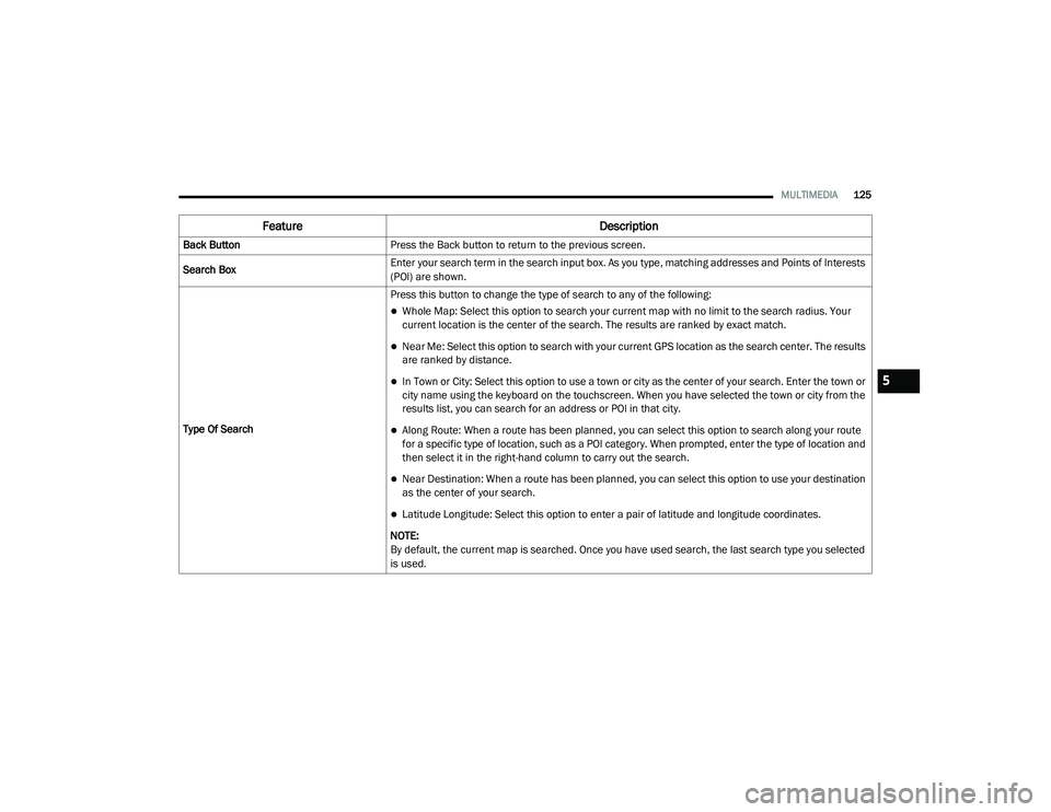
Type Of Search Press this button to change the type of search to any of the following:
Whole Map: Select this option to search your current map with no limit to the search radius. Your
current location is the center of the search. The results are ranked by exact match.
Near Me: Select this option to search with your current GPS location as the search center. The results
are ranked by distance.
In Town or City: Select this option to use a town or city as the center of your search. Enter the town or
city name using the keyboard on the touchscreen. When you have selected the town or city from the
results list, you can search for an address or POI in that city.
Along Route: When a route has been planned, you can select this option to search along your route
for a specific type of location, such as a POI category. When prompted, enter the type of location and
then select it in the right-hand column to carry out the search.
Near Destination: When a route has been planned, you can select this option to use your destination
as the center of your search.
Latitude Longitude: Select this option to enter a pair of latitude and longitude coordinates.
NOTE:
By default, the current map is searched. Once you have used search, the last search type you selected
is used.
5
21_VF_OM_EN_USC_t.book Page 125
Page 129 of 288

MULTIMEDIA127
Planning A Route — Searching For A City Center
When planning a route to a city center, you can
search for a town, city, or postal code.
1. Enter the name of the city or town.
Searching For A City Center
2. Select the Points Of Interest tab.
Addresses List
3. Select the city center POI.
City Center POI
NOTE:
The city center location is shown on the map.
4. Select “Drive”.
Drive Button
As soon as you start driving, the guidance view
is shown automatically.
5
21_VF_OM_EN_USC_t.book Page 127
Page 156 of 288

154SAFETY
Towing With HSA
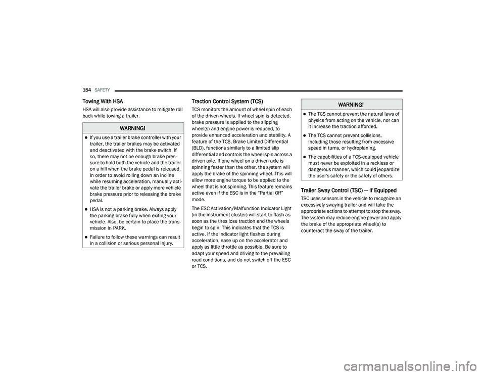
HSA will also provide assistance to mitigate roll
back while towing a trailer.
Traction Control System (TCS)
TCS monitors the amount of wheel spin of each
of the driven wheels. If wheel spin is detected,
brake pressure is applied to the slipping
wheel(s) and engine power is reduced, to
provide enhanced acceleration and stability. A
feature of the TCS, Brake Limited Differential
(BLD), functions similarly to a limited slip
differential and controls the wheel spin across a
driven axle. If one wheel on a driven axle is
spinning faster than the other, the system will
apply the brake of the spinning wheel. This will
allow more engine torque to be applied to the
wheel that is not spinning. This feature remains
active even if the ESC is in the “Partial Off”
mode.
The ESC Activation/Malfunction Indicator Light
(in the instrument cluster) will start to flash as
soon as the tires lose traction and the wheels
begin to spin. This indicates that the TCS is
active. If the indicator light flashes during
acceleration, ease up on the accelerator and
apply as little throttle as possible. Be sure to
adapt your speed and driving to the prevailing
road conditions, and do not switch off the ESC
or TCS.
Trailer Sway Control (TSC) — If Equipped
TSC uses sensors in the vehicle to recognize an
excessively swaying trailer and will take the
appropriate actions to attempt to stop the sway.
The system may reduce engine power and apply
the brake of the appropriate wheel(s) to
counteract the sway of the trailer.
WARNING!
If you use a trailer brake controller with your
trailer, the trailer brakes may be activated
and deactivated with the brake switch. If
so, there may not be enough brake pres -
sure to hold both the vehicle and the trailer
on a hill when the brake pedal is released.
In order to avoid rolling down an incline
while resuming acceleration, manually acti -
vate the trailer brake or apply more vehicle
brake pressure prior to releasing the brake
pedal.
HSA is not a parking brake. Always apply
the parking brake fully when exiting your
vehicle. Also, be certain to place the trans -
mission in PARK.
Failure to follow these warnings can result
in a collision or serious personal injury.
WARNING!
The TCS cannot prevent the natural laws of
physics from acting on the vehicle, nor can
it increase the traction afforded.
The TCS cannot prevent collisions,
including those resulting from excessive
speed in turns, or hydroplaning.
The capabilities of a TCS-equipped vehicle
must never be exploited in a reckless or
dangerous manner, which could jeopardize
the user's safety or the safety of others.
21_VF_OM_EN_USC_t.book Page 154
Page 157 of 288

SAFETY155
NOTE:
TSC cannot stop all trailers from swaying.
Always use caution when towing a trailer and
follow the trailer tongue weight recommenda -
tions Ú page 78.
When TSC is functioning, the ESC Activation/
Malfunction Indicator Light will flash, the engine
power may be reduced, and you may feel the
brakes being applied to individual wheels to
attempt to stop the trailer from swaying. TSC is
disabled when the ESC system is in the “Partial
Off” mode.AUXILIARY DRIVING SYSTEMS
BLIND SPOT MONITORING (BS M) — IF
E
QUIPPED
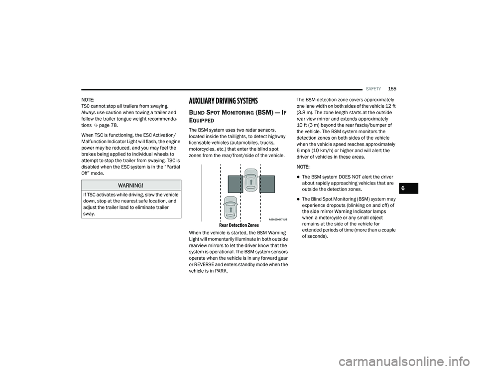
The BSM system uses two radar sensors,
located inside the taillights, to detect highway
licensable vehicles (automobiles, trucks,
motorcycles, etc.) that enter the blind spot
zones from the rear/front/side of the vehicle.
Rear Detection Zones
When the vehicle is started, the BSM Warning
Light will momentarily illuminate in both outside
rearview mirrors to let the driver know that the
system is operational. The BSM system sensors
operate when the vehicle is in any forward gear
or REVERSE and enters standby mode when the
vehicle is in PARK. The BSM detection zone covers approximately
one lane width on both sides of the vehicle 12 ft
(3.8 m). The zone length starts at the outside
rear view mirror and extends approximately
10 ft (3 m) beyond the rear fascia/bumper of
the vehicle. The BSM system monitors the
detection zones on both sides of the vehicle
when the vehicle speed reaches approximately
6 mph (10 km/h) or higher and will alert the
driver of vehicles in these areas.
NOTE:
The BSM system DOES NOT alert the driver
about rapidly approaching vehicles that are
outside the detection zones.
The Blind Spot Monitoring (BSM) system may
experience dropouts (blinking on and off) of
the side mirror Warning Indicator lamps
when a motorcycle or any small object
remains at the side of the vehicle for
extended periods of time (more than a couple
of seconds).
WARNING!
If TSC activates while driving, slow the vehicle
down, stop at the nearest safe location, and
adjust the trailer load to eliminate trailer
sway.
6
21_VF_OM_EN_USC_t.book Page 155
Page 160 of 288

158SAFETY
Rear Cross Path (RCP)
RCP is intended to aid the driver when backing
out of parking spaces where their vision of
oncoming vehicles may be blocked. Proceed
slowly and cautiously out of the parking space
until the rear end of the vehicle is exposed. The
RCP system will then have a clear view of the
cross traffic, and if an oncoming vehicle is
detected, alert the driver.
RCP Detection Zones
RCP monitors the rear detection zones on both
sides of the vehicle, for objects that are moving
toward the side of the vehicle with a minimum
speed of approximately 3 mph (5 km/h), to
objects moving a maximum of approximately
20 mph (32 km/h), such as in parking lot
situations. When RCP is on and the vehicle is in REVERSE
(R), the driver is alerted using both the visual
and audible alarms, including reducing the
radio volume.
NOTE:
In a parking lot situation, oncoming vehicles can
be blocked by vehicles parked on either side. If
the sensors are blocked by other structures or
vehicles, the system will not be able to alert the
driver.
Blind Spot Modes
Blind Spot has three selectable modes of
operation that are available in the Uconnect
system.
Blind Spot Alert Lights Only
When operating in Blind Spot Alert mode, the
BSM system will provide a visual alert in the
appropriate side view mirror based on a
detected object. However, when the system is
operating in Rear Cross Path (RCP) mode, the
system will respond with both visual and
audible alerts when a detected object is
present. Whenever an audible alert is
requested, the radio is muted.
Blind Spot Alert Lights/Chime
When operating in Blind Spot Alert Lights/
Chime mode, the BSM system will provide a
visual alert in the appropriate side view mirror
based on a detected object. If the turn signal is
then activated, and it corresponds to an alert
present on that side of the vehicle, an audible
chime will also be sounded. Whenever a turn
signal and detected object are present on the
same side at the same time, both the visual and
audible alerts will be issued. In addition to the
audible alert the radio (if on) will also be muted.
WARNING!
Rear Cross Path Detection (RCP) is not a
backup aid system. It is intended to be used
to help a driver detect an oncoming vehicle in
a parking lot situation. Drivers must be
careful when backing up, even when using
RCP. Always check carefully behind your
vehicle, look behind you, and be sure to
check for pedestrians, animals, other
vehicles, obstructions, and blind spots before
backing up. Failure to do so can result in
serious injury or death.
21_VF_OM_EN_USC_t.book Page 158
Page 168 of 288

166SAFETY
Enhanced Seat Belt Use Reminder System
(BeltAlert)
Driver and Passenger BeltAlert — If Equipped
BeltAlert is a feature intended to remind the
driver and outboard front seat passenger (if
equipped with outboard front passenger seat
BeltAlert) to buckle their seat belts. The BeltAlert
feature is active whenever the ignition switch is in
the AVV/START or MAR/RUN position.
Initial Indication
If the driver is unbuckled when the ignition
switch is first in the AVV/START or MAR/RUN
position, a chime will signal for a few seconds. If
the driver or outboard front seat passenger (if
equipped with outboard front passenger seat
BeltAlert) is unbuckled when the ignition switch
is first in the AVV/START or MAR/RUN position
the Seat Belt Reminder Light will turn on and
remain on until both outboard front seat belts
are buckled. The outboard front passenger seat
BeltAlert is not active when an outboard front
passenger seat is unoccupied.
BeltAlert Warning Sequence
The BeltAlert warning sequence is activated
when the vehicle is moving above a specified
vehicle speed range and the driver or outboard front seat passenger is unbuckled (if equipped
with outboard front passenger seat BeltAlert)
(the outboard front passenger seat BeltAlert is
not active when the outboard front passenger
seat is unoccupied). The BeltAlert warning
sequence starts by blinking the Seat Belt
Reminder Light and sounding an intermittent
chime. Once the BeltAlert warning sequence
has completed, the Seat Belt Reminder Light
will remain on until the seat belts are buckled.
The BeltAlert warning sequence may repeat
based on vehicle speed until the driver and
occupied outboard front seat passenger seat
belts are buckled. The driver should instruct all
occupants to buckle their seat belts.
Change of Status
If the driver or outboard front seat passenger (if
equipped with outboard front passenger seat
BeltAlert) unbuckles their seat belt while the
vehicle is traveling, the BeltAlert warning
sequence will begin until the seat belts are
buckled again.
The outboard front passenger seat BeltAlert is not
active when the outboard front passenger seat is
unoccupied. BeltAlert may be triggered when an
animal or other items are placed on the outboard
front passenger seat or when the seat is folded
flat (if equipped). It is recommended that pets be
restrained in the rear seat (if equipped) in pet
harnesses or pet carriers that are secured by seat
belts, and cargo is properly stowed.
BeltAlert can be activated or deactivated by an
authorized dealer. FCA US LLC does not
recommend deactivating BeltAlert.
NOTE:
If BeltAlert has been deactivated and the driver
or outboard front seat passenger (if equipped
with outboard front passenger seat BeltAlert) is
unbuckled the Seat Belt Reminder Light will turn
on and remain on until the driver and outboard
front seat passenger seat belts are buckled.
Lap/Shoulder Belts
All seating positions in your vehicle are
equipped with lap/shoulder belts.
The seat belt webbing retractor will lock only
during very sudden stops or collisions. This
feature allows the shoulder part of the seat belt
to move freely with you under normal
conditions. However, in a collision the seat belt
will lock and reduce your risk of striking the
inside of the vehicle or being thrown out of the
vehicle.
21_VF_OM_EN_USC_t.book Page 166
Page 171 of 288

SAFETY169
Positioning The Lap Belt
5. Position the shoulder belt across the shoulder and chest with minimal, if any
slack so that it is comfortable and not
resting on your neck. The retractor will
withdraw any slack in the shoulder belt.
6. To release the seat belt, push the red button on the buckle. The seat belt will automat -
ically retract to its stowed position. If
necessary, slide the latch plate down the
webbing to allow the seat belt to retract
fully.
Lap/Shoulder Belt Untwisting Procedure
Use the following procedure to untwist a twisted
lap/shoulder belt.
1. Position the latch plate as close as possible to the anchor point.
2. At about 6 to 12 inches (15 to 30 cm) above the latch plate, grab and twist the seat belt
webbing 180 degrees to create a fold that
begins immediately above the latch plate.
3. Slide the latch plate upward over the folded webbing. The folded webbing must enter
the slot at the top of the latch plate.
4. Continue to slide the latch plate up until it clears the folded webbing and the seat belt
is no longer twisted.
Adjustable Upper Shoulder Belt Anchorage
In the driver and outboard front passenger
seats, the top of the shoulder belt can be
adjusted upward or downward to position the
seat belt away from your neck. Push or squeeze
the anchorage button to release the anchorage,
and move it up or down to the position that
serves you best.
Adjustable Anchorage
6
21_VF_OM_EN_USC_t.book Page 169
Page 190 of 288

188SAFETY
(Continued)
PERIODIC SAFETY CHECKS YOU SHOULD
M
AKE OUTSIDE THE VEHICLE
Tires
Examine tires for excessive tread wear and
uneven wear patterns. Check for stones, nails,
glass, or other objects lodged in the tread or
sidewall. Inspect the tread for cuts and cracks.
Inspect sidewalls for cuts, cracks, and bulges.
Check the lug nut/bolt torque for tightness.
Check the tires (including spare) for proper cold
inflation pressure.
Lights
Have someone observe the operation of brake
lights and exterior lights while you work the
controls. Check turn signal and high beam
indicator lights on the instrument panel.
Door Latches
Check for proper closing, latching, and locking.
ONLY install floor mats designed to fit your
vehicle. NEVER install a floor mat that
cannot be properly attached and secured to
your vehicle. If a floor mat needs to be
replaced, only use a FCA approved floor
mat for the specific make, model, and year
of your vehicle.
ONLY use the driver’s side floor mat on the
driver’s side floor area. To check for inter -
ference, with the vehicle properly parked
with the engine off, fully depress the accel -
erator, the brake, and the clutch pedal (if
present) to check for interference. If your
floor mat interferes with the operation of
any pedal, or is not secure to the floor,
remove the floor mat from the vehicle and
place the floor mat in your trunk.
ONLY use the passenger’s side floor mat on
the passenger’s side floor area.
ALWAYS make sure objects cannot fall or
slide into the driver’s side floor area when
the vehicle is moving. Objects can become
trapped under accelerator, brake, or clutch
pedals and could cause a loss of vehicle
control.
WARNING! (Continued)
NEVER place any objects under the floor
mat (e.g., towels, keys, etc.). These objects
could change the position of the floor mat
and may cause interference with the accel -
erator, brake, or clutch pedals.
If the vehicle carpet has been removed and
re-installed, always properly attach carpet
to the floor and check the floor mat
fasteners are secure to the vehicle carpet.
Fully depress each pedal to check for inter -
ference with the accelerator, brake, or
clutch pedals then re-install the floor mats.
It is recommended to only use mild soap
and water to clean your floor mats. After
cleaning, always check your floor mat has
been properly installed and is secured to
your vehicle using the floor mat fasteners
by lightly pulling mat.
WARNING! (Continued)
21_VF_OM_EN_USC_t.book Page 188