engine Ram ProMaster City 2020 User Guide
[x] Cancel search | Manufacturer: RAM, Model Year: 2020, Model line: ProMaster City, Model: Ram ProMaster City 2020Pages: 350, PDF Size: 13.27 MB
Page 55 of 350
52 GETTING TO KNOW YOUR VEHICLE
Windshield Washers
Pull the windshield wiper/washer lever toward the steering
wheel to activate the washers. The wipers will activate auto-
matically for three cycles after the lever is released. Manual High Speed/Mist
Push the lever upward from the off position. The wipers will
operate at high speed to clear off road mist or spray from a
passing vehicle. This operation will continue until the lever
is released. When the lever is released, the wipers will return
to the off position and automatically shut off.
Rear Wiper Operation — If Equipped
Rear Windshield Wiper Operation
Rotate the windshield wiper lever center ring upwards to
operate the rear window wiper as follows:
• In intermittent mode when the front window wiper is not
operating
• In synchronous mode (at half the speed of the front window wiper) when the front window wiper is operating
• In continuous mode while vehicle is in REVERSE
With the windshield wipers on, and REVERSE gear engaged,
rear window wiping will be continuous in the same way.
CAUTION!
• Turn the windshield wipers off when driving through an automatic car wash. Damage to the windshield
wipers may result if the wiper control is left in any
position other than off.
• In cold weather, always turn off the wiper switch and allow the wipers to return to the park position before
turning off the engine. If the wiper switch is left on and
the wipers freeze to the windshield, damage to the
wiper motor may occur when the vehicle is restarted.
• Always remove any buildup of snow that prevents the windshield wiper blades from returning to the off posi -
tion. If the windshield wiper control is turned off and
the blades cannot return to the off position, damage to
the wiper motor may occur.
2020_RAM_PROMASTER_CITY_OM_USA=GUID-7B6A7FCA-79B0-423F-95C5-ED2A949C3D13=1=en=.book Page 52
Page 60 of 350
GETTING TO KNOW YOUR VEHICLE 57
air conditioning and manually adjust the blower and airflow
mode settings. Also, make sure to select only Panel, Bi-Level
or Floor modes.
NOTE:
• For Manual Climate Controls, if the system is in Mix orDefrost Mode, the A/C can be turned off, but the A/C
system shall remain active to prevent fogging of the
windows.
• If fog or mist appears on the windshield or side glass, select Defrost mode, and increase blower speed if needed.
• If your air conditioning performance seems lower than expected, check the front of the A/C condenser (located in
front of the radiator), for an accumulation of dirt or insects.
Clean with a gentle water spray from the front of the radi -
ator and through the condenser.
Recirculation
In cold weather, use of Recirculation mode may lead to
excessive window fogging. The Recirculation feature may be
unavailable if conditions exist that could create fogging on
the inside of the windshield. The recirculation mode is not
allowed in Defrost mode to improve window clearing oper -
ation. On systems with Manual Climate Controls (if equipped) the
Recirculation mode is not allowed in Defrost mode to
improve window clearing operation. Recirculation is
disabled automatically if this mode is selected. Attempting
to use Recirculation while in this mode causes the LED in the
control button to blink and then turns off.
Operating Tips
NOTE:
Refer to the chart at the end of this section for suggested
control settings for various weather conditions.
Summer Operation
The engine cooling system must be protected with a
high-quality antifreeze coolant to provide proper corrosion
protection and to protect against engine overheating. Organic
Additive Technology (OAT) coolant (conforming to MS.90032)
is recommended. Refer to “Fluids And Lubricants” in “Tech
-
nical Specifications” for proper coolant selection.
2
2020_RAM_PROMASTER_CITY_OM_USA=GUID-7B6A7FCA-79B0-423F-95C5-ED2A949C3D13=1=en=.book Page 57
Page 61 of 350
58 GETTING TO KNOW YOUR VEHICLE
Winter Operation
To ensure the best possible heater and defroster perfor-
mance, make sure the engine cooling system is functioning
properly and the proper amount, type, and concentration of
coolant is used. Refer to “Fluids And Lubricants” in “Tech -
nical Specifications” for proper coolant selection. Use of the
air recirculation mode during Winter months is not recom -
mended because it may cause window fogging.
Vacation/Storage
Any time you store your vehicle or keep it out of service (i.e.,
vacation) for two weeks or more, run the air conditioning
system at idle for about five minutes in fresh air with the
blower setting on high. This will ensure adequate system
lubrication to minimize the possibility of compressor
damage when the system is started again. Window Fogging
Vehicle windows tend to fog on the inside of the glass in mild,
rainy and/or humid weather. Windows may frost on the inside
of the glass in very cold weather. To clear the windows, select
Defrost or Mix mode and increase the front blower speed. Do
not use the Recirculation mode without Air Conditioning (A/C)
for long periods, as fogging may occur.
CAUTION!
Failure to follow these cautions can cause damage to the
heating elements:
• Use care when washing the inside of the rear window. Do not use abrasive window cleaners on the interior
surface of the window. Use a soft cloth and a mild
washing solution, wiping parallel to the heating
elements. Labels can be peeled off after soaking with
warm water.
• Do not use scrapers, sharp instruments, or abrasive window cleaners on the interior surface of the window.
• Keep all objects a safe distance from the window.
2020_RAM_PROMASTER_CITY_OM_USA=GUID-7B6A7FCA-79B0-423F-95C5-ED2A949C3D13=1=en=.book Page 58
Page 75 of 350
72 GETTING TO KNOW YOUR VEHICLE
(Continued)
ROOF RACK — IF EQUIPPED
The crossbars and siderails are designed to carry the weight
on vehicles equipped with a luggage rack. The load must not
exceed 150 lbs (68 kg), and should be uniformly distributed
over the luggage rack crossbars.
NOTE:
If not equipped with crossbars, an authorized dealer can
order and install Mopar crossbars built specifically for this
roof rack system.
WARNING!
To avoid serious injury or death:
• Only devices designed for use in this type of outlet should be inserted into any 12 Volt outlet.
• Do not touch with wet hands.
• Close the lid when not in use and while driving the vehicle.
• If this outlet is mishandled, it may cause an electric shock and failure.
CAUTION!
• Many accessories that can be plugged in draw power from the vehicle's battery, even when not in use (i.e.,
cellular phones, etc.). Eventually, if plugged in long
enough, the vehicle's battery will discharge sufficiently
to degrade battery life and/or prevent the engine from
starting.
• Accessories that draw higher power (i.e., coolers,vacuum cleaners, lights, etc.) will degrade the battery
even more quickly. Only use these intermittently and
with greater caution.
• After the use of high power draw accessories, or long periods of the vehicle not being started (with accesso -
ries still plugged in), the vehicle must be driven a suffi -
cient length of time to allow the generator to recharge
the vehicle's battery. CAUTION!
(Continued)
2020_RAM_PROMASTER_CITY_OM_USA=GUID-7B6A7FCA-79B0-423F-95C5-ED2A949C3D13=1=en=.book Page 72
Page 79 of 350
76 GETTING TO KNOW YOUR INSTRUMENT PANEL
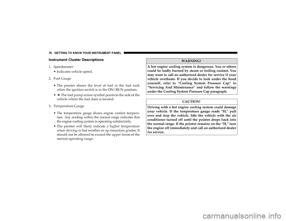
Instrument Cluster Descriptions
1. Speedometer• Indicates vehicle speed.
2. Fuel Gauge
• The pointer shows the level of fuel in the fuel tankwhen the ignition switch is in the ON/RUN position.
• The fuel pump arrow symbol points to the side of the vehicle where the fuel door is located.
3. Temperature Gauge
• The temperature gauge shows engine coolant tempera-ture. Any reading within the normal range indicates that
the engine cooling system is operating satisfactorily.
• The pointer will likely indicate a higher temperature when driving in hot weather or up mountain grades. It
should not be allowed to exceed the upper limits of the
normal operating range.
WARNING!
A hot engine cooling system is dangerous. You or others
could be badly burned by steam or boiling coolant. You
may want to call an authorized dealer for service if your
vehicle overheats. If you decide to look under the hood
yourself, refer to “Cooling System Pressure Cap” in
“Servicing And Maintenance” and follow the warnings
under the Cooling System Pressure Cap paragraph.
CAUTION!
Driving with a hot engine cooling system could damage
your vehicle. If the temperature gauge reads “H,” pull
over and stop the vehicle. Idle the vehicle with the air
conditioner turned off until the pointer drops back into
the normal range. If the pointer remains on the “H,” turn
the engine off immediately and call an authorized dealer
for service.
2020_RAM_PROMASTER_CITY_OM_USA=GUID-7B6A7FCA-79B0-423F-95C5-ED2A949C3D13=1=en=.book Page 76
Page 80 of 350
GETTING TO KNOW YOUR INSTRUMENT PANEL 77
4. Tachometer• Indicates the engine speed in revolutions per minute(RPM x 1000).
5. Instrument Cluster Display
• When the appropriate conditions exist, this displayshows the instrument cluster display messages. Refer
to “Instrument Cluster Display” in this chapter for
further information.
INSTRUMENT CLUSTER DISPLAY
Your vehicle will be equipped with an instrument cluster
display, which offers useful information to the driver. With
the ignition in the OFF mode, opening/closing of a door will
activate the display for viewing, and display the total miles,
or kilometers, in the odometer. Your instrument cluster
display is designed to display important information about
your vehicle’s systems and features. Using a driver interac -
tive display located on the instrument panel, your instru-
ment cluster display can show you how systems are working and give you warnings when they are not. The instrument
cluster display controls allow you to scroll through the main
menus and submenus. You can access the specific informa
-
tion you want and make selections and adjustments.
Location And Controls
The instrument cluster display features a driver interactive
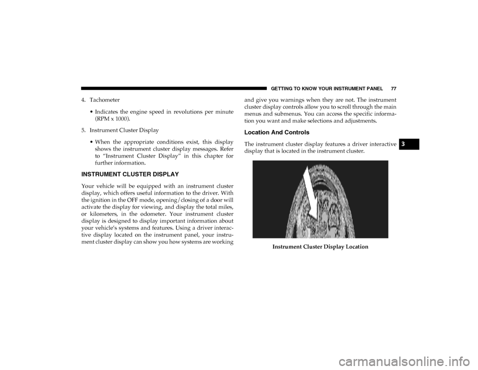
display that is located in the instrument cluster.
Instrument Cluster Display Location3
2020_RAM_PROMASTER_CITY_OM_USA=GUID-7B6A7FCA-79B0-423F-95C5-ED2A949C3D13=1=en=.book Page 77
Page 83 of 350
80 GETTING TO KNOW YOUR INSTRUMENT PANEL
Change Engine Oil — If Equipped
Your vehicle may be equipped with an engine oil change
indicator system. The “Change Engine Oil” message will
display in the instrument cluster display. The engine oil
change indicator system is duty cycle based, which means
the engine oil change interval may fluctuate, dependent
upon your personal driving style.
Unless reset, this message will continue to display each time
you turn the ignition switch to the ON/RUN position. To
turn off the message temporarily, push and release the
MENU button. To reset the oil change indicator system (after
performing the scheduled maintenance), refer to the
following procedure.
1. Turn the ignition switch to the ON position (do not start the engine).
2. Fully push the accelerator pedal slowly, three times, within 10 seconds.
3. Turn the ignition switch to the OFF/LOCK position.
NOTE:
If the indicator message illuminates when you start the
vehicle, the oil change indicator system did not reset. If
necessary, repeat this procedure.
Instrument Cluster Display Menu Items
Speed Beep
This function is used to set a speed limit (MPH or km/h); the
driver is alerted when this limit is exceeded.
To set the desired speed limit:
1. Push the MENU button briefly. The display will show the
wording (SPEED BEEP) and the unit (MPH) or (km/h)
previously set.
2. If the function is on, push and release the up or down
arrow button to select the required speed limit and then
push MENU to confirm.
NOTE:
The speed may be set in the range from 20 to 125 MPH (30 to
200 km/h) according to the previously chosen unit.
The setting will increase/decrease by five units each time the
up or down arrow button is pushed. Hold down the up or
down arrow button to automatically increase/decrease the
setting rapidly. Complete the adjustment when you
approach the desired value.
2020_RAM_PROMASTER_CITY_OM_USA=GUID-7B6A7FCA-79B0-423F-95C5-ED2A949C3D13=1=en=.book Page 80
Page 86 of 350

GETTING TO KNOW YOUR INSTRUMENT PANEL 83
Start Of Trip Procedure
With the ignition on, push and hold the TRIP button for over
two seconds to reset trip information.
Exit Trip
1. To exit the Trip function, wait until all the values havebeen displayed or hold the MENU button for longer than
one second.
2. Briefly push and release the MENU button to go back to the menu screen or push and hold the MENU button
(approximately one second) to go back to the main screen
without storing settings.
Trip Functions
Both trip functions are resettable (reset — start of new trip).
“Trip A” can be used to display the figures relating to:
• Range
• Trip distance A
• Average Economy A
• Instantaneous Economy • Average speed A
• Travel time A (driving time)
“Trip B” can be used to display the figures relating to:
• Trip distance B
• Average Economy B
• Average speed B
• Travel time B (driving time)
NOTE:
“Trip B” functions may be excluded (see “Trip B Data”).
“Range” and “Instantaneous Economy” cannot be reset.
Values Displayed
Range
This indicates the distance which may be traveled with the
fuel remaining in the tank, assuming that driving conditions
will not change. The message “----” will appear on the
display in the following cases:
• Distance less than 30 miles (or 50 km).
• The vehicle is parked for a long time with the engine
running.
3
2020_RAM_PROMASTER_CITY_OM_USA=GUID-7B6A7FCA-79B0-423F-95C5-ED2A949C3D13=1=en=.book Page 83
Page 87 of 350
84 GETTING TO KNOW YOUR INSTRUMENT PANEL
NOTE:
The range depends on several factors: driving style, type of
route (freeway, residential, mountain roads, etc.), conditions
of use of the vehicle (load, tire pressure, etc.). Trip planning
must take into account the above notes.
Travel Distance
This value shows the distance covered since the last reset.
Average Fuel Consumption
This value shows the approximate average consumption
since the last reset.
Current Fuel Consumption
This indicates the fuel consumption. The value is constantly
updated. The message “----” will appear on the display if the
vehicle is parked with the engine running.
Average Speed
This value shows the vehicle's average speed as a function of
the overall time elapsed since the last reset.
Travel Time
This value shows the time elapsed since the last reset.WARNING LIGHTS AND MESSAGES
The warning/indicator lights will illuminate in the instrument
panel together with a dedicated message and/or acoustic signal
when applicable. These indications are indicative and precau-
tionary and as such must not be considered as exhaustive and/
or alternative to the information contained in the Owner’s
Manual, which you are advised to read carefully in all cases.
Always refer to the information in this chapter in the event of a
failure indication. All active telltales will display first if appli -
cable. The system check menu may appear different based upon
equipment options and current vehicle status. Some telltales are
optional and may not appear.
Red Warning Lights
Air Bag Warning Light
This light will turn on for four to eight seconds as a bulb
check when the ignition is placed in the ON/RUN or
MAR/ON/RUN position. If the light is either not on
during startup, stays on, or turns on while driving, have the
system inspected at an authorized dealer as soon as possible.
This light will illuminate with a single chime when a fault with
the Air Bag Warning Light has been detected, it will stay on until
the fault is cleared. If the light comes on intermittently or
remains on while driving, have an authorized dealer service the
vehicle immediately.
2020_RAM_PROMASTER_CITY_OM_USA=GUID-7B6A7FCA-79B0-423F-95C5-ED2A949C3D13=1=en=.book Page 84
Page 89 of 350

86 GETTING TO KNOW YOUR INSTRUMENT PANEL
Operation of the Brake Warning Light can be checked by turning
the ignition switch from the OFF position to the ON/RUN posi-
tion. The light should illuminate for approximately two seconds.
The light should then turn off unless the parking brake is applied
or a brake fault is detected. If the light does not illuminate, have
the light inspected by an authorized dealer.
The light also will turn on when the parking brake is applied
with the ignition switch in the ON/RUN position.
NOTE:
This light shows only that the parking brake is applied. It
does not show the degree of brake application.
Battery Charge Warning Light
This warning light will illuminate when the battery
is not charging properly. If it stays on while the
engine is running, there may be a malfunction with
the charging system. Contact an authorized dealer as soon as
possible.
This indicates a possible problem with the electrical system
or a related component. Door Open Warning Light
This indicator will illuminate when one or more
door(s) are not fully closed.
NOTE:
If the vehicle is moving and a door is opened, there will also
be a single chime.
Electronic Throttle Control (ETC) Warning Light This warning light will illuminate to inform of a
problem with the Electronic Throttle Control (ETC)
system. If a problem is detected while the vehicle is
running, the light will either stay on or flash depending on
the nature of the problem. Cycle the ignition when the
vehicle is safely and completely stopped and the transmis -
sion is placed in the PARK (P) position. The light should turn
off. If the light remains on with the vehicle running, your
vehicle will usually be drivable; however, see an authorized
dealer for service as soon as possible.
2020_RAM_PROMASTER_CITY_OM_USA=GUID-7B6A7FCA-79B0-423F-95C5-ED2A949C3D13=1=en=.book Page 86