RAM PROMASTER CITY 2022 Owners Manual
Manufacturer: RAM, Model Year: 2022, Model line: PROMASTER CITY, Model: RAM PROMASTER CITY 2022Pages: 260, PDF Size: 8.45 MB
Page 171 of 260
SAFETY169
(Continued)
(Continued)
PERIODIC SAFETY CHECKS YOU SHOULD
M
AKE OUTSIDE THE VEHICLE
Tires
Examine tires for excessive tread wear and uneven
wear patterns. Check for stones, nails, glass, or
other objects lodged in the tread or sidewall.
Inspect the tread for cuts and cracks. Inspect
sidewalls for cuts, cracks, and bulges. Check the
lug nut/bold torque for tightness. Check the tires
(including spare) for proper cold inflation pressure.
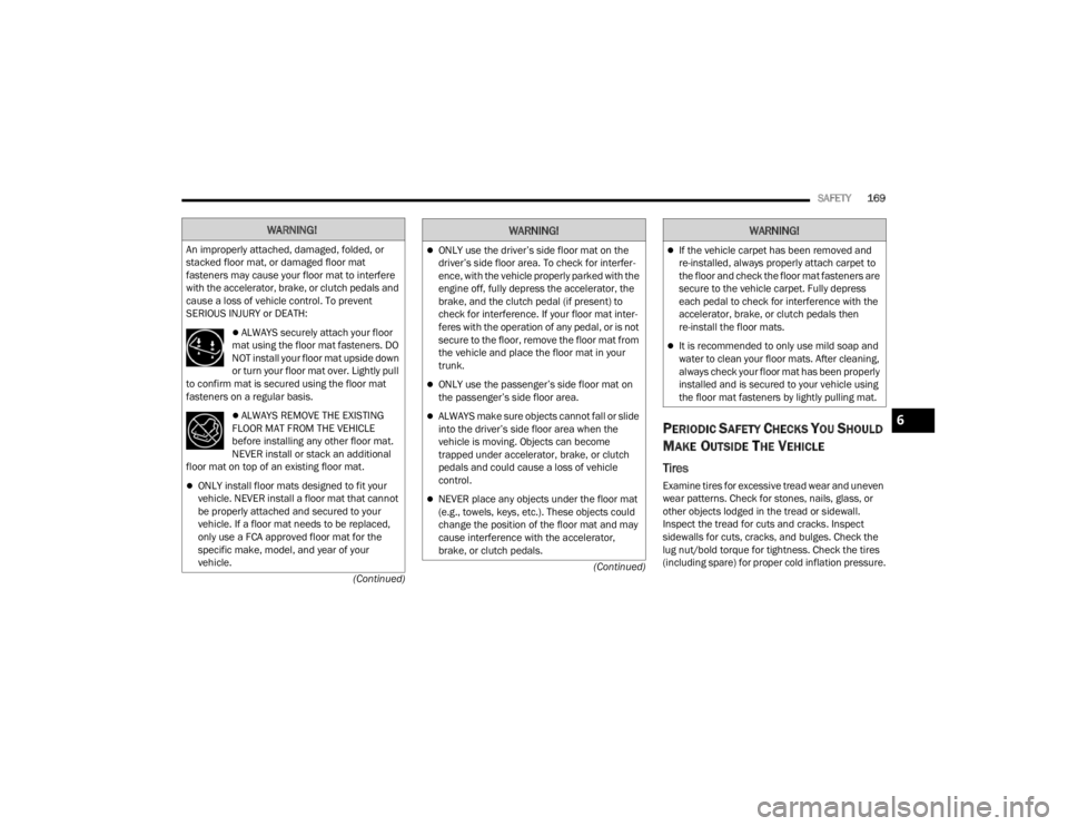
WARNING!
An improperly attached, damaged, folded, or
stacked floor mat, or damaged floor mat
fasteners may cause your floor mat to interfere
with the accelerator, brake, or clutch pedals and
cause a loss of vehicle control. To prevent
SERIOUS INJURY or DEATH:
ALWAYS securely attach your floor
mat using the floor mat fasteners. DO
NOT install your floor mat upside down
or turn your floor mat over. Lightly pull
to confirm mat is secured using the floor mat
fasteners on a regular basis.
ALWAYS REMOVE THE EXISTING
FLOOR MAT FROM THE VEHICLE
before installing any other floor mat.
NEVER install or stack an additional
floor mat on top of an existing floor mat.
ONLY install floor mats designed to fit your
vehicle. NEVER install a floor mat that cannot
be properly attached and secured to your
vehicle. If a floor mat needs to be replaced,
only use a FCA approved floor mat for the
specific make, model, and year of your
vehicle.
ONLY use the driver’s side floor mat on the
driver’s side floor area. To check for interfer -
ence, with the vehicle properly parked with the
engine off, fully depress the accelerator, the
brake, and the clutch pedal (if present) to
check for interference. If your floor mat inter -
feres with the operation of any pedal, or is not
secure to the floor, remove the floor mat from
the vehicle and place the floor mat in your
trunk.
ONLY use the passenger’s side floor mat on
the passenger’s side floor area.
ALWAYS make sure objects cannot fall or slide
into the driver’s side floor area when the
vehicle is moving. Objects can become
trapped under accelerator, brake, or clutch
pedals and could cause a loss of vehicle
control.
NEVER place any objects under the floor mat
(e.g., towels, keys, etc.). These objects could
change the position of the floor mat and may
cause interference with the accelerator,
brake, or clutch pedals.
WARNING!
If the vehicle carpet has been removed and
re-installed, always properly attach carpet to
the floor and check the floor mat fasteners are
secure to the vehicle carpet. Fully depress
each pedal to check for interference with the
accelerator, brake, or clutch pedals then
re-install the floor mats.
It is recommended to only use mild soap and
water to clean your floor mats. After cleaning,
always check your floor mat has been properly
installed and is secured to your vehicle using
the floor mat fasteners by lightly pulling mat.
WARNING!
6
22_VM_OM_EN_USC_t.book Page 169
Page 172 of 260

170SAFETY
(Continued)
Lights
Have someone observe the operation of brake
lights and exterior lights while you work the
controls. Check turn signal and high beam
indicator lights on the instrument panel.
Door Latches
Check for proper closing, latching, and locking.
Fluid Leaks
Check area under the vehicle after overnight
parking for fuel, coolant, oil, or other fluid leaks.
Also, if gasoline fumes are detected or if fuel or
brake fluid leaks are suspected, the cause should
be located and corrected immediately.
EXHAUST GAS
The best protection against carbon monoxide entry
into the vehicle body is a properly maintained
engine exhaust system.
Whenever a change is noticed in the sound of the
exhaust system, when exhaust fumes can be
detected inside the vehicle, or when the underside
or rear of the vehicle is damaged, have an
authorized dealer inspect the complete exhaust
system and adjacent body areas for broken,
damaged, deteriorated, or mispositioned parts.
Open seams or loose connections could permit
exhaust fumes to seep into the passenger
compartment. In addition, inspect the exhaust
system each time the vehicle is raised for
lubrication or oil change. Replace as required.
CARBON MONOXIDE WARNINGS
WARNING!
Exhaust gases can injure or kill. They contain
carbon monoxide (CO), which is colorless and
odorless. Breathing it can make you
unconscious and can eventually poison you. To
avoid breathing (CO), follow these safety tips:
Do not run the engine in a closed garage or in
confined areas any longer than needed to
move your vehicle in or out of the area.
If you are required to drive with the trunk/lift -
gate/rear doors open, make sure that all
windows are closed and the climate control
BLOWER switch is set at high speed. DO NOT
use the recirculation mode.
If it is necessary to sit in a parked vehicle with
the engine running, adjust your heating or
cooling controls to force outside air into the
vehicle. Set the blower at high speed.
WARNING!
WARNING!
Carbon monoxide (CO) in exhaust gases is
deadly. Follow the precautions below to prevent
carbon monoxide poisoning:
Do not inhale exhaust gases. They contain
carbon monoxide, a colorless and odorless
gas, which can kill. Never run the engine in a
closed area, such as a garage, and never sit in
a parked vehicle with the engine running for
an extended period. If the vehicle is stopped in
an open area with the engine running for more
than a short period, adjust the ventilation
system to force fresh, outside air into the
vehicle.
Guard against carbon monoxide with proper
maintenance. Have the exhaust system
inspected every time the vehicle is raised.
Have any abnormal conditions repaired
promptly. Until repaired, drive with all side
windows fully open.
22_VM_OM_EN_USC_t.book Page 170
Page 173 of 260
171
(Continued)
IN CASE OF EMERGENCY
HAZARD WARNING FLASHERS
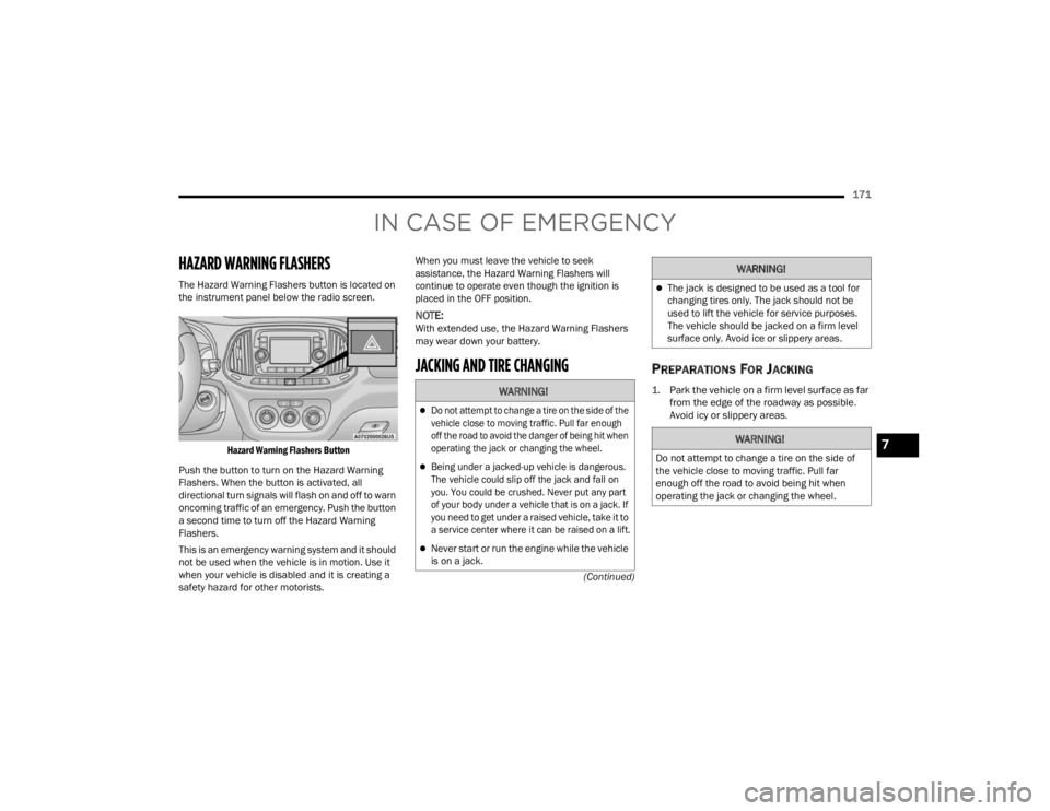
The Hazard Warning Flashers button is located on
the instrument panel below the radio screen.
Hazard Warning Flashers Button
Push the button to turn on the Hazard Warning
Flashers. When the button is activated, all
directional turn signals will flash on and off to warn
oncoming traffic of an emergency. Push the button
a second time to turn off the Hazard Warning
Flashers.
This is an emergency warning system and it should
not be used when the vehicle is in motion. Use it
when your vehicle is disabled and it is creating a
safety hazard for other motorists. When you must leave the vehicle to seek
assistance, the Hazard Warning Flashers will
continue to operate even though the ignition is
placed in the OFF position.
NOTE:With extended use, the Hazard Warning Flashers
may wear down your battery.
JACKING AND TIRE CHANGING PREPARATIONS FOR JACKING
1. Park the vehicle on a firm level surface as far
from the edge of the roadway as possible.
Avoid icy or slippery areas.
WARNING!
Do not attempt to change a tire on the side of the
vehicle close to moving traffic. Pull far enough
off the road to avoid the danger of being hit when
operating the jack or changing the wheel.
Being under a jacked-up vehicle is dangerous.
The vehicle could slip off the jack and fall on
you. You could be crushed. Never put any part
of your body under a vehicle that is on a jack. If
you need to get under a raised vehicle, take it to
a service center where it can be raised on a lift.
Never start or run the engine while the vehicle
is on a jack.
The jack is designed to be used as a tool for
changing tires only. The jack should not be
used to lift the vehicle for service purposes.
The vehicle should be jacked on a firm level
surface only. Avoid ice or slippery areas.
WARNING!
Do not attempt to change a tire on the side of
the vehicle close to moving traffic. Pull far
enough off the road to avoid being hit when
operating the jack or changing the wheel.
WARNING!
7
22_VM_OM_EN_USC_t.book Page 171
Page 174 of 260
172IN CASE OF EMERGENCY
2. Turn on the Hazard Warning Flashers.
3. Apply the parking brake.
4. Place the gear selector into PARK (P).
5. Turn the ignition to the STOP (OFF/LOCK) position.
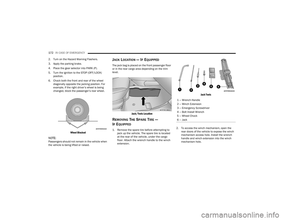
6. Chock both the front and rear of the wheel diagonally opposite the jacking position. For
example, if the right driver’s wheel is being
changed, block the passenger’s rear wheel.
Wheel Blocked
NOTE:Passengers should not remain in the vehicle when
the vehicle is being lifted or raised.
JACK LOCATION — IF EQUIPPED
The jack bag is placed on the front passenger floor
or in the rear cargo area depending on the trim
level.
Jack/Tools Location
REMOVING THE SPARE TIRE —
I
F EQUIPPED
1. Remove the spare tire before attempting to
jack up the vehicle. The spare tire is located
at the rear of the vehicle, under the cargo
floor. Attach the wrench handle to the winch
extension.
Jack Tools
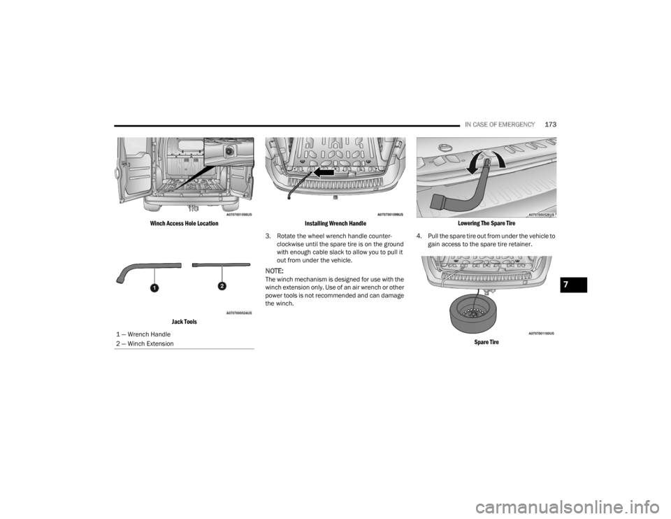
2. To access the winch mechanism, open the rear doors of the vehicle to expose the winch
mechanism access hole. Install the wrench
handle and winch extension into the winch
mechanism hole.
1 — Wrench Handle
2 — Winch Extension
3 — Emergency Screwdriver
4 — Bolt Install Wrench
5 — Wheel Chock
6 — Jack
22_VM_OM_EN_USC_t.book Page 172
Page 175 of 260
IN CASE OF EMERGENCY173
Winch Access Hole Location Jack Tools Installing Wrench Handle
3. Rotate the wheel wrench handle counter -
clockwise until the spare tire is on the ground
with enough cable slack to allow you to pull it
out from under the vehicle.
NOTE:The winch mechanism is designed for use with the
winch extension only. Use of an air wrench or other
power tools is not recommended and can damage
the winch.
Lowering The Spare Tire
4. Pull the spare tire out from under the vehicle to gain access to the spare tire retainer.
Spare Tire
1 — Wrench Handle
2 — Winch Extension7
22_VM_OM_EN_USC_t.book Page 173
Page 176 of 260
174IN CASE OF EMERGENCY
(Continued)
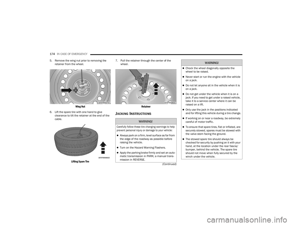
5. Remove the wing nut prior to removing the
retainer from the wheel.
Wing Nut
6. Lift the spare tire with one hand to give clearance to tilt the retainer at the end of the
cable.
Lifting Spare Tire
7. Pull the retainer through the center of the
wheel.
Retainer
JACKING INSTRUCTIONS
WARNING!
Carefully follow these tire changing warnings to help
prevent personal injury or damage to your vehicle:
Always park on a firm, level surface as far from
the edge of the roadway as possible before
raising the vehicle.
Turn on the Hazard Warning Flashers.
Apply the parking brake firmly and set an auto -
matic transmission in PARK; a manual trans -
mission in REVERSE.
Chock the wheel diagonally opposite the
wheel to be raised.
Never start or run the engine with the vehicle
on a jack.
Do not let anyone sit in the vehicle when it is
on a jack.
Do not get under the vehicle when it is on a
jack. If you need to get under a raised vehicle,
take it to a service center where it can be
raised on a lift.
Only use the jack in the positions indicated
and for lifting this vehicle during a tire change.
If working on or near a roadway, be extremely
careful of motor traffic.
To ensure that spare tires, flat or inflated, are
securely stowed, spares must be stowed with
the valve stem facing the ground.
The stowed spare tire should always be
checked for security by pushing on it with your
hand, at the location under the rear fascia/
bumper, behind the vehicle. The spare tire
should not move when fully secured by the
winch under the vehicle.
WARNING!
22_VM_OM_EN_USC_t.book Page 174
Page 177 of 260

IN CASE OF EMERGENCY175
Jack Warning Label
Placement for the front and rear jacking locations
are critical. See below images for proper jacking
locations.
Jacking Locations
1. Loosen (but do not remove) the wheel lug
bolts with the wrench handle by turning them
to the left one turn while the wheel is still on
the ground.
2. There are two jack engagement locations on each side of the vehicle body.
NOTE:Place the jack underneath the jack engagement
location that is closest to the flat tire.
Front Lifting Point Front Jacking Location
Rear Lifting Point
7
22_VM_OM_EN_USC_t.book Page 175
Page 178 of 260
176IN CASE OF EMERGENCY
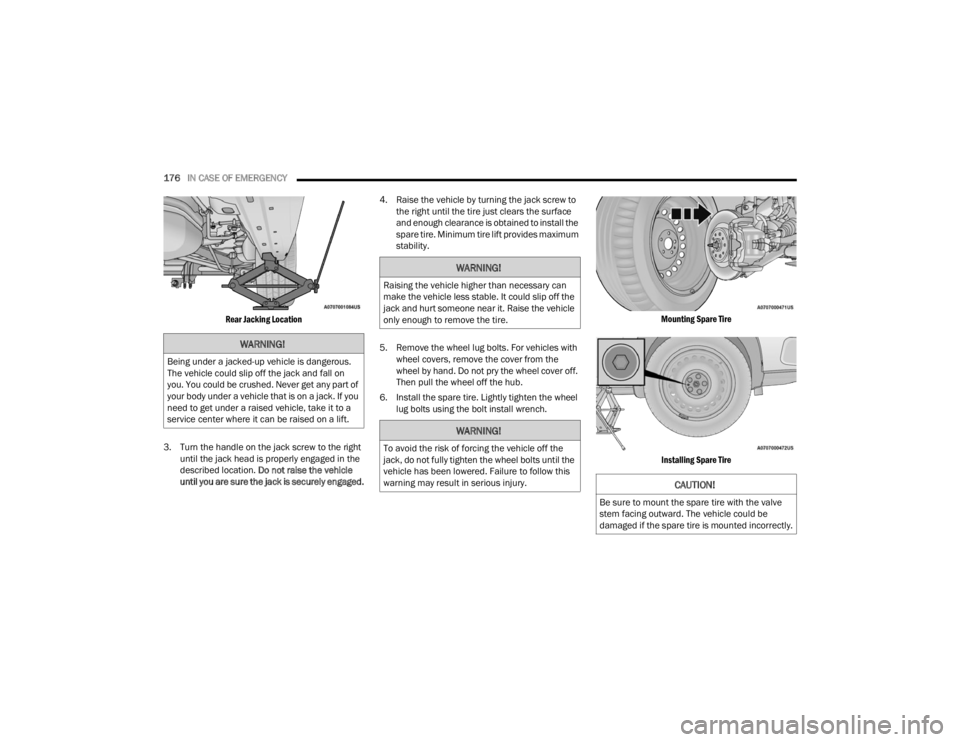
Rear Jacking Location
3. Turn the handle on the jack screw to the right until the jack head is properly engaged in the
described location. Do not raise the vehicle
until you are sure the jack is securely engaged. 4. Raise the vehicle by turning the jack screw to
the right until the tire just clears the surface
and enough clearance is obtained to install the
spare tire. Minimum tire lift provides maximum
stability.
5. Remove the wheel lug bolts. For vehicles with wheel covers, remove the cover from the
wheel by hand. Do not pry the wheel cover off.
Then pull the wheel off the hub.
6. Install the spare tire. Lightly tighten the wheel lug bolts using the bolt install wrench.
Mounting Spare Tire
Installing Spare Tire
WARNING!
Being under a jacked-up vehicle is dangerous.
The vehicle could slip off the jack and fall on
you. You could be crushed. Never get any part of
your body under a vehicle that is on a jack. If you
need to get under a raised vehicle, take it to a
service center where it can be raised on a lift.
WARNING!
Raising the vehicle higher than necessary can
make the vehicle less stable. It could slip off the
jack and hurt someone near it. Raise the vehicle
only enough to remove the tire.
WARNING!
To avoid the risk of forcing the vehicle off the
jack, do not fully tighten the wheel bolts until the
vehicle has been lowered. Failure to follow this
warning may result in serious injury.
CAUTION!
Be sure to mount the spare tire with the valve
stem facing outward. The vehicle could be
damaged if the spare tire is mounted incorrectly.
22_VM_OM_EN_USC_t.book Page 176
Page 179 of 260
IN CASE OF EMERGENCY177
7. Lower the vehicle by turning the jack screw to the left Ú page 236.
8. Lower the jack to its fully-closed position.
9. Stow the cable and wheel spacer before driving the vehicle Ú page 177.
10. Stow the jack and tools under the driver’s seat.
11. Check the spare tire pressure as soon as possible. Correct the tire pressure, as
required.
12. When you place the spare tire back on the winch or if you carry the tire in need of repair
on the winch, always check that the tire is
properly secured under the vehicle by pushing
on the stowed tire under the rear fascia/
bumper at the back of the vehicle. If the tire
has motion when pushed, use the tools to
re-tighten the winch until a loud click is heard.
VEHICLES WITH ALLOY WHEELS
For stowing a damaged tire on vehicles with alloy
wheels, remove the adapter bracket and bolts
from the storage bag in the glove compartment
and follow the steps below:
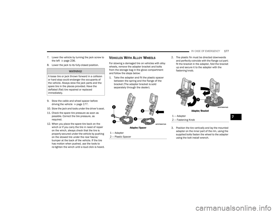
1. Take the adapter and fit the plastic spacer between the spring and the flange of the
bracket (The adapter bracket is sold
separately through the dealer).
Adapter/Spacer
2. The plastic fin must be directed downwards
and perfectly coincide with the flange cut part;
fit the bracket in the adapter, fold the bracket
up and secure it to the adapter with the
fastening knob.
Adapter/Bracket
3. Position the tire vertically and lay the mounted adapter on the inner part of the rim, using the
supplied bolts fasten the wheel to the adapter
using the bolt install wrench.
WARNING!
A loose tire or jack thrown forward in a collision
or hard stop could endanger the occupants of
the vehicle. Always stow the jack parts and the
spare tire in the places provided. Have the
deflated (flat) tire repaired or replaced
immediately.
1 — Adapter
2 — Plastic Spacer
1 — Adapter
2 — Fastening Knob7
22_VM_OM_EN_USC_t.book Page 177
Page 180 of 260
178IN CASE OF EMERGENCY
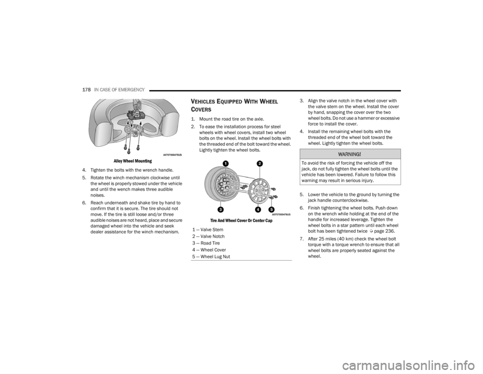
Alloy Wheel Mounting
4. Tighten the bolts with the wrench handle.
5. Rotate the winch mechanism clockwise until the wheel is properly stowed under the vehicle
and until the wench makes three audible
noises.
6. Reach underneath and shake tire by hand to confirm that it is secure. The tire should not
move. If the tire is still loose and/or three
audible noises are not heard, place and secure
damaged wheel into the vehicle and seek
dealer assistance for the winch mechanism.
VEHICLES EQUIPPED WITH WHEEL
C
OVERS
1. Mount the road tire on the axle.
2. To ease the installation process for steel
wheels with wheel covers, install two wheel
bolts on the wheel. Install the wheel bolts with
the threaded end of the bolt toward the wheel.
Lightly tighten the wheel bolts.
Tire And Wheel Cover Or Center Cap
3. Align the valve notch in the wheel cover with
the valve stem on the wheel. Install the cover
by hand, snapping the cover over the two
wheel bolts. Do not use a hammer or excessive
force to install the cover.
4. Install the remaining wheel bolts with the threaded end of the wheel bolt toward the
wheel. Lightly tighten the wheel bolts.
5. Lower the vehicle to the ground by turning the jack handle counterclockwise.
6. Finish tightening the wheel bolts. Push down on the wrench while holding at the end of the
handle for increased leverage. Tighten the
wheel bolts in a star pattern until each wheel
bolt has been tightened twice Ú page 236.
7. After 25 miles (40 km) check the wheel bolt torque with a torque wrench to ensure that all
wheel bolts are properly seated against the
wheel.
1 — Valve Stem
2 — Valve Notch
3 — Road Tire
4 — Wheel Cover
5 — Wheel Lug Nut
WARNING!
To avoid the risk of forcing the vehicle off the
jack, do not fully tighten the wheel bolts until the
vehicle has been lowered. Failure to follow this
warning may result in serious injury.
22_VM_OM_EN_USC_t.book Page 178