check engine light RENAULT ALASKAN 2017 Owner's Manual
[x] Cancel search | Manufacturer: RENAULT, Model Year: 2017, Model line: ALASKAN, Model: RENAULT ALASKAN 2017Pages: 340, PDF Size: 6.93 MB
Page 233 of 340
hicle straight, accelerate or decelerate or
move the vehicle in reverse, then shift the
4WD mode switch.
• If the 4WD warning light comes on or 4WD Er-
ror warning (where fitted) appears, the 4WD
mode indicator turns off.
4WD WARNING
Warning light Warning light
Comes on or
blinks when:
m Illuminates
There
is a
malfunction in the
4WD system
m Blinks
The
difference in
wheel rotation is large
If the 4WD warning light comes on, the 4WD mode
indicator turns off.
Al arge difference between the diameters of front
and rear wheels will make the 4WD warning light
blink. Change the 4WD mode switch to <2WD>
and do not drive fast.
CAUTION
• If the 4WD warning light comes on or blinks
during operation for
awhile, have your ve-
hicle checked by an approved dealer or quali-
fied workshop as soon as possible. •
Shifting between <4H> and <4LO> is not rec-
ommended when the 4WD warning light turns
on.
• When the 4WD warning light comes on, the
2WD mode may be engaged even if the 4WD
mode switch is in <4H>. Be especially careful
when driving. If corresponding parts are mal-
functioning, the 4WD mode will not be en-
gaged even if the 4WD mode switch is shifted.
• Do not drive the vehicle in the <4H> or <4LO>
position on dry hard surface roads. Driving on
dry, hard surfaces in <4H> or <4LO> may
cause unnecessary noise, tyre wear and in-
creased fuel consumption.
If the Four-Wheel Drive (4WD) warning light
turns on when driving on dry hard surface
roads:
–i nthe <4H> position, shift the 4WD mode
switch to <2WD>.
–i nthe <4LO> position, stop the vehicle and
shift the transmission lever to the N(Neu-
tral) position with the brake pedal
depressed and shift the 4WD mode switch
to <2WD>.
If the 4WD warning light is still on after the
above operation, have your vehicle
checked by an approved dealer or quali-
fied workshop as soon as possible. •
The transfer case may be damaged if you con-
tinue driving with the warning light blinking.
Warning indicator
If any malfunction occurs in the Four-Wheel Drive
(4WD) system while the engine is running, awarn-
ing message appears in the vehicle information dis-
play.
If the [4WD system fault] warning appears, there
may be amalfunction in the 4WD system. Reduce
vehicle speed and have your vehicle checked by an
approved dealer or qualified workshop as soon as
possible.
CAUTION
• Do not operate the engine on
afree roller
when any of the wheels raised.
• If the [4WD system fault] warning appears
while driving, there may be
amalfunction in
the 4WD system. Reduce the vehicle speed
and have your vehicle checked by an
approved dealer or qualified workshop as
soon as possible. Be especially careful when
driving.
• The power train may be damaged if you con-
tinue driving with the [4WD system fault] warn-
ing on.
Starting and driving 5-31
Page 234 of 340
TYRE RECOMMENDATION FOR 4WD
CAUTION
• Always use tyres of the same size, brand, con-
struction (bias, bias-belted or radial), and
tread pattern on all four wheels. Failure to do
so may result in acircumference difference
between tyres on the front and rear axles,
which will cause excessive tyre wear and may damage the transmission, transfer case and
differential gears.
• ONLY use spare tyres specified for the Four-
Wheel Drive (4WD) models.
If excessive tyre wear is found, it is recommended
that all four tyres be replaced with tyres of the same
size, brand, construction and tread pattern. The tyre
pressure and wheel alignment should also be
checked and corrected as necessary. Contact an
approved dealer or qualified workshop.
Snow tyres
If you install snow tyres, they must also be of the
same size, brand, construction and tread pattern on
all four wheels.
Tyre inflation pressure
Periodically check the pressures of all tyres, includ-
ing the spare, with agauge while at aservice sta-
tion. If necessary, adjust to the specified pressure.
Tyre pressures are shown on the tyre placard af-
fixed to the driver’s side centre pillar or rear access
door. Tyre rotation
RENAULT recommends that tyres should be rotated
every 5,000 km (3,000 miles).
Snow chains
Snow chains must be installed only on the rear
wheels and not on the front wheels.
Do not drive with snow chains on paved roads that are clear of snow. Driving with chains in such condi-
tions can cause damage to the various mechanisms of the vehicle due to overstress. When driving on
clear paved roads, be sure to change to Two-Wheel
Drive (2WD) mode. The rear differential lock is designed to transmit en-
gine power to the left and right rear wheels equally.
If your vehicle is stuck in sand, snow, mud, etc. or
one wheel is off the ground and the differential lock
is not on, engine power is transmitted to the wheel
with least resistance causing it to spin, leaving insuf-
ficient traction on the other wheel. The rear differen-
tial lock allows the left and right wheels to rotate as
au
nit, enabling your vehicle to free itself.
To lock the rear differential gear:
1) Stop the vehicle completely.
2) Turn the 4WD mode switch to the 4LO position. For operation of the 4WD mode switch, see
“Four-Wheel Drive (4WD) (where fitted)” earlier
in this section.
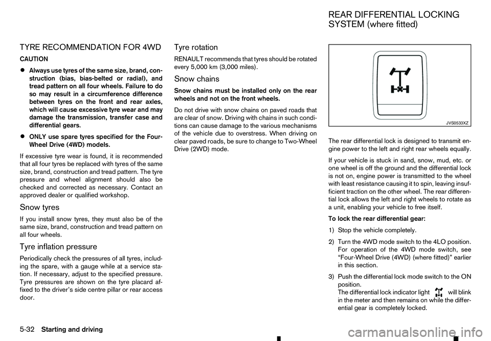
3) Push the differential lock mode switch to the ON position.
The differential lock indicator light will blink
in the meter and then remains on while the differ-
ential gear is completely locked. JVS0533XZ
REAR DIFFERENTIAL LOCKING
SYSTEM (where fitted)
5-32 Starting and driving
Page 239 of 340
Models with colour display:
1. Using the or switches and the
button on the left side of the steering wheel, se-
lect the Settings menu in the vehicle information
display. (See “Vehicle information display” in the
“2. Instruments and controls” section
2. Using the or switches and the
button, navigate to the [Driver Assistance] menu,
followed by the [Driving Aids] menu.
3. In the [Driving Aids] menu, highlight the [Emer- gency Brake] item and use the
to toggle between ON (enabled) or OFF (dis-
abled).
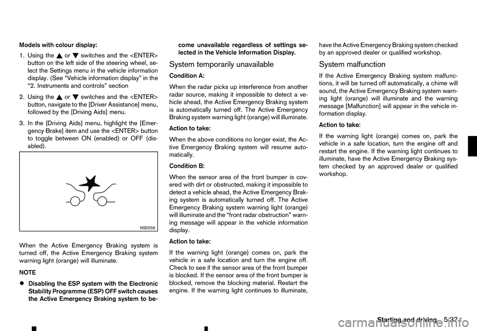
When the Active Emergency Braking system is
turned off, the Active Emergency Braking system
warning light (orange) will illuminate.
NOTE • Disabling the ESP system with the Electronic
Stability Programme (ESP) OFF switch causes
the Active Emergency Braking system to be- come unavailable regardless of settings se-
lected in the Vehicle Information Display.
System temporarily unavailable
Condition A:
When the radar picks up interference from another
radar source, making it impossible to detect ave-
hicle ahead, the Active Emergency Braking system
is automatically turned off. The Active Emergency
Braking system warning light (orange) will illuminate.
Action to take:
When the above conditions no longer exist, the Ac-
tive Emergency Braking system will resume auto-
matically.
Condition B:
When the sensor area of the front bumper is cov-
ered with dirt or obstructed, making it impossible to
detect avehicle ahead, the Active Emergency Brak-
ing system is automatically turned off. The Active
Emergency Braking system warning light (orange)
will illuminate and the “front radar obstruction” warn-
ing message will appear in the vehicle information
display.
Action to take:
If the warning light (orange) comes on, park the
vehicle in asafe location and turn the engine off.
Check to see if the sensor area of the front bumper
is blocked. If the sensor area of the front bumper is
blocked, remove the blocking material. Restart the
engine. If the warning light continues to illuminate, have the Active Emergency Braking system checked
by an approved dealer or qualified workshop.
System malfunction
If the Active Emergency Braking system malfunc-
tions, it will be turned off automatically, achime will
sound, the Active Emergency Braking system warn-
ing light (orange) will illuminate and the warning
message [Malfunction] will appear in the vehicle in-
formation display.
Action to take:
If the warning light (orange) comes on, park the
vehicle in asafe location, turn the engine off and
restart the engine. If the warning light continues to
illuminate, have the Active Emergency Braking sys-
tem checked by an approved dealer or qualified
workshop. NSD556
Starting and driving
5-37
Page 250 of 340
Your new vehicle was designed to be used primarily
to carry passengers and luggage.
Towing atrailer will place additional loads on your
vehicle’s engine, drive train, steering, braking and
other systems. The towing of atrailer will exagger-
ate other conditions such as sway caused by cross-
winds, rough road surfaces or passing trucks.
Your driving style and speed must be adjusted ac-
cording to the circumstances. Before towing a
trailer, see an approved dealer or qualified work-
shop for an explanation about the proper use of tow-
ing equipment.
OPERATING PRECAUTIONS
• Avoid towing
atrailer during the running-in pe-
riod.
• Before driving, make sure that the lighting sys-
tem of the trailer works properly.
• Observe the legal maximum speeds for trailer
operation.
• Avoid abrupt starts, accelerations and stops.
• Avoid sharp turns and lane changes.
• Always drive your vehicle at
amoderate speed.
• Follow the trailer manufacturer’s instructions.
• Choose proper coupling devices (trailer hitch,
safety chain, roof carrier, etc.) for your vehicle
and trailer. These devices are available from an
approved dealer or qualified workshop where
you can also obtain more detailed information
about trailer towing. •
Never allow the total trailer load (trailer weight
plus its cargo weight) to exceed the maximum
set for the vehicle and the coupling device. See
an approved dealer or qualified workshop for
more information.
• The trailer must be loaded so that heavy goods
are placed over the axle. The maximum allowable
vertical load on the trailer hitch must not be ex-
ceeded.
• Have your vehicle serviced more often than at
the intervals specified in
aseparate maintenance
booklet.
• Trailer towing requires more fuel than under nor-
mal circumstances because of
aconsiderable
increase in traction power and resistance.
While towing atrailer, check the engine coolant
temperature indicator to prevent the vehicle from
overheating.
TYRE PRESSURE
When towing atrailer, inflate the vehicle tyres to the
maximum recommended COLD tyre pressure (for
full loading) indicated on the tyre placard.
Do not tow atrailer when the vehicle is installed with
at emporary spare tyre or acompact spare tyre.
SAFETY CHAINS
Always use asuitable chain between the vehicle
and trailer. The chain should be crossed and should
be attached to the hitch, not to the vehicle bumper
or axle. Be sure to leave enough slack in the chain
to permit turning corners. TRAILER BRAKES
Ensure that trailer brakes are installed as required
by local regulations. Also check that all other trailer
equipment conforms to local regulations.
Always block the wheels on both the vehicle and
trailer when parking. Apply the hand brake on the
trailer where fitted. Parking on
asteep slope is not
recommended.
If parking on asteep slope is unavoidable, place the
shift lever in the P(Park) position (Automatic trans-
mission model), or in an appropriate position
(Manual transmission model), and turn the front
wheels towards the kerb.
TRAILER DETECTION (where fitted)
When towing atrailer with agenuine RENAULT tow
bar electrical kit and the turn signal switch is used,
the electrical system of the vehicle will detect the
additional electrical load of the trailer lighting. As a
result, the direction indicator tone will be different.
TRAILER TOWING
5-48
Starting and driving
Page 252 of 340
While driving on
aslippery surface, be careful when
braking, accelerating or downshifting. Abrupt brak-
ing or acceleration could cause the wheels to skid
and result in an accident.
Wet brakes
When the vehicle is washed or driven through wa-
ter, the brakes may get wet. As aresult, your brak-
ing distance will be longer and the vehicle may pull
to one side during braking.
To dry the brakes, drive the vehicle at asafe speed
while lightly depressing the footbrake pedal to heat
up the brakes. Do this until the brakes return to nor-
mal. Avoid driving the vehicle at high speeds until
the brakes function correctly.
Parking brake running-in
Break in the parking brake shoes whenever the
stopping effect of the parking brake is weakened or
whenever the parking brake shoes and/or drums/
rotors are replaced, in order to assure the best brak-
ing performance.
This procedure is described in the vehicle service
manual and can be performed by an approved dealer
or qualified workshop.
ANTI-LOCK BRAKING SYSTEM (ABS) WARNING
The Anti-lock Braking System (ABS) is
asophis-
ticated device, but it cannot prevent accidents
resulting from careless or dangerous driving
techniques. It can help maintain vehicle control during braking on slippery surfaces. Remember
that stopping distances on slippery surfaces will
be longer than on normal surfaces even with ABS.
Stopping distances may also be longer on rough,
gravel or snow covered roads, or if you are using
tyre chains. Always maintain
asafe distance from
the vehicle in front of you. Ultimately, the driver
is responsible for safety.
Tyre type and condition may also affect braking
effectiveness.
• When replacing tyres, install the specified size
of tyres on all four wheels.
• When installing
aspare tyre, make sure that it
is the proper size and type as specified on the
tyre placard. (See “Vehicle identification” in
the “9. Technical information” section.)
• For detailed information, see “Tyres and
wheels” in the “9. Technical information” sec-
tion.
The Anti-lock Braking System (ABS) controls the
brakes so the wheels do not lock during hard brak-
ing or when braking on slippery surfaces. The sys-
tem detects the rotation speed at each wheel and
varies the brake fluid pressure to prevent each wheel
from locking and sliding. By preventing each wheel
from locking, the system helps the driver maintain
steering control and helps to minimise swerving and
spinning on slippery surfaces. Using system
Depress the brake pedal and hold it down. Depress
the brake pedal with firm steady pressure, but do
not pump the brakes. The ABS will operate to pre-
vent the wheels from locking up. Steer the vehicle to
avoid obstacles. WARNING
Do not pump the brake pedal. Doing so may re-
sult in increased stopping distances.
Self-test feature
The ABS includes electronic sensors, electric
pumps, hydraulic solenoids and acomputer. The
computer has abuilt-in diagnostic feature that tests
the system each time you start the engine and move
the vehicle at alow speed in forward or reverse.
When the self-test occurs, you may hear a“clunk”
noise and/or feel apulsation in the brake pedal. This
is normal and does not indicate amalfunction. If the
computer senses amalfunction, it switches the ABS
off and illuminates the ABS warning light on the
instrument panel. The brake system then operates
normally, but without anti-lock assistance. If the ABS
warning light illuminates during the self-test or while
driving, have the vehicle checked by an approved
dealer or qualified workshop.
Normal operation
The ABS operates at speeds above 5to10km/h (3
to 6M PH). The speed varies according to road con-
ditions.
5-50 Starting and driving
Page 253 of 340
When the ABS senses that one or more wheels are
close to locking up, the actuator rapidly applies and
releases hydraulic pressure. This action is similar to
pumping the brakes very quickly. You may feel a
pulsation in the brake pedal and hear anoise from
under the bonnet or feel avibration from the actua-
tor when it is operating. This is normal and indicates
that the ABS is operating properly. However, the
pulsation may indicate that road conditions are haz-
ardous and extra care is required while driving.
When the differential lock (where fitted) is engaged,
the ABS warning light illuminates. This indicates that
the anti-lock function is not fully operating. (See
“Rear differential locking system (where fitted)” ear-
lier in this section for the rear differential lock func-
tion.) WARNING
• Whatever the condition, drive with caution.
Accelerate and decelerate with great care. If
accelerating or decelerating too fast, the drive
wheels will lose even more traction.
• Allow more stopping distance in cold weather
driving. Braking should be started sooner than
on dry pavement.
• Keep at
agreater distance from the vehicle in
front of you on slippery roads.
• Wet ice (0°C, 32°F and freezing rain), very cold
snow and ice can be slick and very difficult to
drive on. The vehicle will have
alot less trac-
tion or grip under these conditions. Try to
avoid driving on wet ice until the road is salted
or sanded.
• Watch for slippery spots (glaring ice). These
may appear on an otherwise clear road in
shaded areas. If
apatch of ice is seen ahead,
brake before reaching it. Try not to brake while
actually on the ice, and avoid any sudden
steering manoeuvres.
• Do not use cruise control on slippery roads.
• Snow can trap dangerous exhaust gas under
your vehicle. Keep snow clear of the exhaust
pipe and from around your vehicle. BATTERY
If the battery is not fully charged during extremely
cold weather conditions, the battery fluid may freeze
and damage the battery. To maintain maximum effi-
ciency, the battery should be checked regularly. For
details, see “Battery” in the “8. Maintenance and
do-it-yourself” section of this manual.
ENGINE COOLANT
If the vehicle is to be left outside without anti-freeze,
drain the cooling system, including the engine block.
Refill before operating the vehicle. For details, see
“Engine cooling system” in the “8. Maintenance and
do-it-yourself” section of this manual.
TYRE EQUIPMENT
1. If you have snow tyres installed on the front/rear
wheels of your vehicle, they should be of the
same size, loading range, construction and type
(bias, bias-belted or radial) as the rear/front tyres.
2. If the vehicle is to be operated in severe winter conditions, snow tyres should be installed on all
four wheels.
3. For additional traction on icy roads, studded tyres may be used. However, some countries, prov-
inces and states prohibit their use. Check local,
state and provincial laws before installing stud-
ded tyres.
Skid and traction capabilities of studded snow
tyres, on wet or dry surfaces, may be poorer
than that of non-studded snow tyres.
COLD WEATHER DRIVING
Starting and driving5-51
Page 277 of 340
8
Maintenance and do-it-yourself
Maintenance and do-it-yourself
Maintenance requirements ....................................... 8-2 Scheduled maintenance...................................... 8-2
General maintenance .......................................... 8-2
Where to go for service ...................................... 8-2
General maintenance ............................................... 8-2 Explanation of general maintenance items ........... 8-2
Maintenance precautions .................................... 8-4
Engine compartment check locations ....................... 8-5
Engine cooling system ............................................. 8-5 Checking engine coolant level............................. 8-6
Changing engine coolant .................................... 8-6
Engine oil................................................................. 8-6
Checking engine oil level .................................... 8-6
Changing engine oil and oil filter ......................... 8-7
Protect environment ............................................ 8-7
AdBlue® tank (where fitted for diesel engine
model) ..................................................................... 8-7 Refilling the AdBlue® tank .................................. 8-7
Drive belt ................................................................. 8-8
Automatic Transmission Fluid (ATF) (where fitted).... 8-8 7-speed Automatic Transmission (AT) model....... 8-8
Power steering fluid ................................................. 8-8
Brakes ..................................................................... 8-9 Checking parking brake ...................................... 8-9
Checking footbrake ............................................ 8-9
Brake booster ..................................................... 8-9
Brake fluid ............................................................... 8-10
Clutch fluid (where fitted) ......................................... 8-11 Window washer fluid ............................................... 8-11
Battery..................................................................... 8-12
Vehicle battery .................................................... 8-13
Remote controller battery (where fitted) .............. 8-13
Remote Control Key battery (where fitted)........... 8-14
Air cleaner filter........................................................ 8-15
Wiper blades ........................................................... 8-16 Windscreen wiper blades ................................... 8-16
Variable voltage control system (where fitted) ........... 8-17
Fuses ...................................................................... 8-18 Engine compartment ........................................... 8-18
Passenger compartment ..................................... 8-19
Lights ...................................................................... 8-20
Headlights .......................................................... 8-20
Exterior lights ...................................................... 8-21
Interior lights....................................................... 8-22
Light locations .................................................... 8-23
Tyres and wheels ..................................................... 8-26 Tyre inflation pressure......................................... 8-26
Types of tyres ..................................................... 8-26
Tyre chains ......................................................... 8-27
Tyre rotation ....................................................... 8-27
Tyre wear and damage ....................................... 8-28
Tyre age ............................................................. 8-28
Changing tyres and wheels................................. 8-28
Wheel balance.................................................... 8-28
Spare tyre .......................................................... 8-28
Page 285 of 340
CHECKING PARKING BRAKE
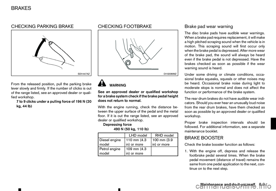
From the released position, pull the parking brake
lever slowly and firmly. If the number of clicks is out
of the range listed, see an approved dealer or quali- fied workshop.
7to9c licks under apulling force of 196 N(20
kg, 44 lb) CHECKING FOOTBRAKE WARNING
See an approved dealer or qualified workshop
for abrake system check if the brake pedal height
does not return to normal.
With the engine running, check the distance be-
tween the upper surface of the pedal and the metal
floor. If it is out the range listed, see an approved
dealer or qualified workshop. Depressing force
490N(50 kg, 110 lb) LHD model RHD model
Diesel engine
model 110 mm (4.3
in) or more100 mm (3.9
in) or more
Petrol engine
model 109 mm (4.3
in) or more Brake pad wear warning
The disc brake pads have audible wear warnings.
When
abrake pad requires replacement, it will make
ah igh pitched scraping sound when the vehicle is in
motion. This scraping sound will first occur only
when the brake pedal is depressed. After more wear
of the brake pad, the sound will always be heard
even if the brake pedal is not depressed. Have the
brakes checked as soon as possible if the wear
warning sound is heard.
Under some driving or climate conditions, occa-
sional brake squeaks, squeals or other noises may
be heard. Occasional brake noise during light to
moderate stops is normal and does not affect the
function or performance of the brake system.
The rear drum brakes do not have audible wear indi-
cators. Should you ever hear an unusually loud noise
from the rear drum brakes, have them checked as
soon as possible by an approved dealer or qualified
workshop.
Proper brake inspection intervals should be
followed. For additional information, see aseparate
maintenance booklet.
BRAKE BOOSTER
Check the brake booster function as follows:
1. With the engine off, depress and release the footbrake pedal several times. When the brake
pedal movement (distance of travel) remains the
same from one pedal application to the next, con-
tinue on to the next step. SDI1447AZ DI1020MMZ
BRAKES
Maintenance and do-it-yourself
8-9
Page 286 of 340
2. While depressing the footbrake pedal, start the
engine. The pedal height should drop alittle.
3. With the footbrake pedal depressed, stop the engine. Keep the pedal depressed for about 30
seconds. The pedal height should not change.
4. Run the engine for 1minute without depressing
the footbrake pedal, then turn it off. Depress the
footbrake pedal several times. The pedal travel
distance will decrease gradually with each de-
pression as the vacuum is released from the
booster.
If the brakes do not operate properly, have the
brakes checked by an approved dealer or qualified
workshop. WARNING
• Use only new fluid from
asealed container.
Old, inferior, or contaminated fluid may dam-
age the brake system. The use of improper
fluids can damage the brake system and af-
fect the vehicle’s stopping ability.
• Clean the filler cap before removing.
• Brake fluid is poisonous and should be stored
carefully in marked containers out of the reach
of children.
CAUTION
• Refilling and checking the brake system
should be left to an approved dealer or quali-
fied workshop who will have the necessary
brake fluid and technical knowledge.
• Do not spill the fluid on painted surfaces. This
will damage the paint. If fluid is spilled, wash
with water.
For details of recommended fluids, refer to the main-
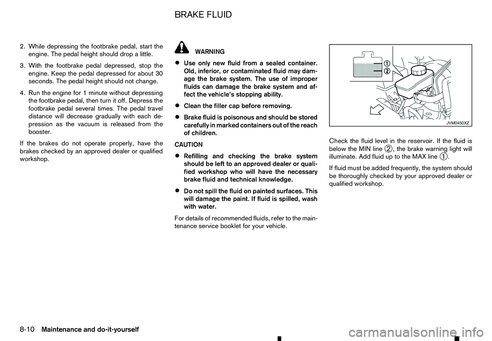
tenance service booklet for your vehicle. Check the fluid level in the reservoir. If the fluid is
below the MIN line
➁,t
he brake warning light will
illuminate. Add fluid up to the MAX line ➀.
If fluid must be added frequently, the system should
be thoroughly checked by your approved dealer or
qualified workshop. JVM0450XZ
BRAKE FLUID
8-10 Maintenance and do-it-yourself
Page 294 of 340
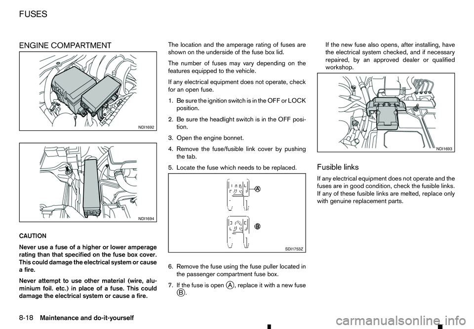
ENGINE COMPARTMENT
CAUTION
Never use afuse of ahigher or lower amperage
rating than that specified on the fuse box cover.
This could damage the electrical system or cause
af ire.
Never attempt to use other material (wire, alu-
minium foil. etc.) in place of afuse. This could
damage the electrical system or cause afire. The location and the amperage rating of fuses are
shown on the underside of the fuse box lid.
The number of fuses may vary depending on the
features equipped to the vehicle.
If any electrical equipment does not operate, check
for an open fuse.
1. Be sure the ignition switch is in the OFF or LOCK
position.
2. Be sure the headlight switch is in the OFF posi- tion.
3. Open the engine bonnet.
4. Remove the fuse/fusible link cover by pushing the tab.
5. Locate the fuse which needs to be replaced.
6. Remove the fuse using the fuse puller located in the passenger compartment fuse box.
7. If the fuse is open j
A, replace it with anew fuse
j B. If the new fuse also opens, after installing, have
the electrical system checked, and if necessary
repaired, by an approved dealer or qualified
workshop.
Fusible links
If any electrical equipment does not operate and the
fuses are in good condition, check the fusible links.
If any of these fusible links are melted, replace only
with genuine replacement parts. NDI1692
NDI1694
SDI1753Z NDI1693
FUSES
8-18
Maintenance and do-it-yourself