stop start RENAULT ALASKAN 2017 Owner's Guide
[x] Cancel search | Manufacturer: RENAULT, Model Year: 2017, Model line: ALASKAN, Model: RENAULT ALASKAN 2017Pages: 340, PDF Size: 6.93 MB
Page 231 of 340
WARNING
AT model: If the 4WD mode indicator is “OFF” or
the ATP warning light is “ON”, this indicates that
the automatic transmission P(Park) position will
not function and could result in the vehicle mov-
ing unexpectedly, causing serious personal in-
jury or property damage. Always set the parking
brake.
CAUTION
To avoid vehicle damage:
• Do not operate the 4WD mode switch when
cornering, reversing or if the rear wheels are
spinning freely. The vehicle must be moving
straight ahead.
• Do not move the shift lever (AT model) or
release the clutch pedal (MT model) when the
4LO indicator is blinking. Failure to do this
may cause the gears to grind and damaging
the powertrain.
• MT model: Do not accelerate rapidly from a
stopped position when the 4LO indicator is
blinking. Drive straight ahead at
alow speed
until the 4LO indicator is lit. The 4LO indicator
blinks when shifting between <4LO> and
<4H>.
• If the 4WD warning light comes on, perform
the following procedure:
1) Turn off the engine.
2) Start the engine. 3) Check if the 4WD warning light comes on.
If the 4WD warning light is still on after following
the above procedure, have the system checked
and serviced immediately by an approved dealer
or qualified workshop.
The transfer case 4WD mode switch is used to
select either Two-Wheel Drive (2WD) or
Four-Wheel Drive (4WD) depending on the driving
conditions. Turn the 4WD mode switch to select a drive mode (<2WD>, <4H> or <4LO>).
To change into or out of 4LO mode:
1. The vehicle MUST BE standing still.
2. Depress the clutch pedal (MT model) and the brake pedal and move the shift lever to N(Neu-
tral).
3. Depress and turn the 4WD mode switch to change into or out of <4LO>. WARNING
• When parking, apply the parking brake before
stopping the engine and make sure that the
4WD mode indicator is on and that the ATP
warning light or ATP warning message is off,
otherwise, the vehicle could unexpectedly
move even if the automatic transmission is in
the P(Park) position.
• The 4LO indicator must stop blinking and re-
main on or turn off before shifting the trans-
mission into gear. The vehicle may move un- expectedly if the shift lever is shifted from the
N(
Neutral) position to any other gear while
the 4LO indicator is blinking.
CAUTION
• Never turn the 4WD mode switch between
<4LO> and <4H> while driving.
• The <4H> drive mode provides greater power
and traction. Avoid excessive speed as it will
cause increased fuel consumption and higher
oil temperatures, and could damage power
train components. Speeds over 100 km/h (60
MPH) in <4H> are not recommended.
• The <4LO> drive mode provides maximum
power and traction. Avoid raising vehicle
speed excessively. The maximum speed is
approximately 50 km/h (30 MPH).
• The 4WD mode switch can be turned between
<2WD> and <4H> while driving straight ahead.
Do not turn the 4WD mode switch while mak-
ing
aturn or reversing.
• Do not turn the 4WD mode switch between
<2WD> and <4H> while driving on steep
downhill grades. Use the engine brake and
low transmission gears for engine braking.
• Do not turn the 4WD mode switch between
<2WD> and <4H> with the rear wheels spin-
ning.
Starting and driving 5-29
Page 233 of 340
hicle straight, accelerate or decelerate or
move the vehicle in reverse, then shift the
4WD mode switch.
• If the 4WD warning light comes on or 4WD Er-
ror warning (where fitted) appears, the 4WD
mode indicator turns off.
4WD WARNING
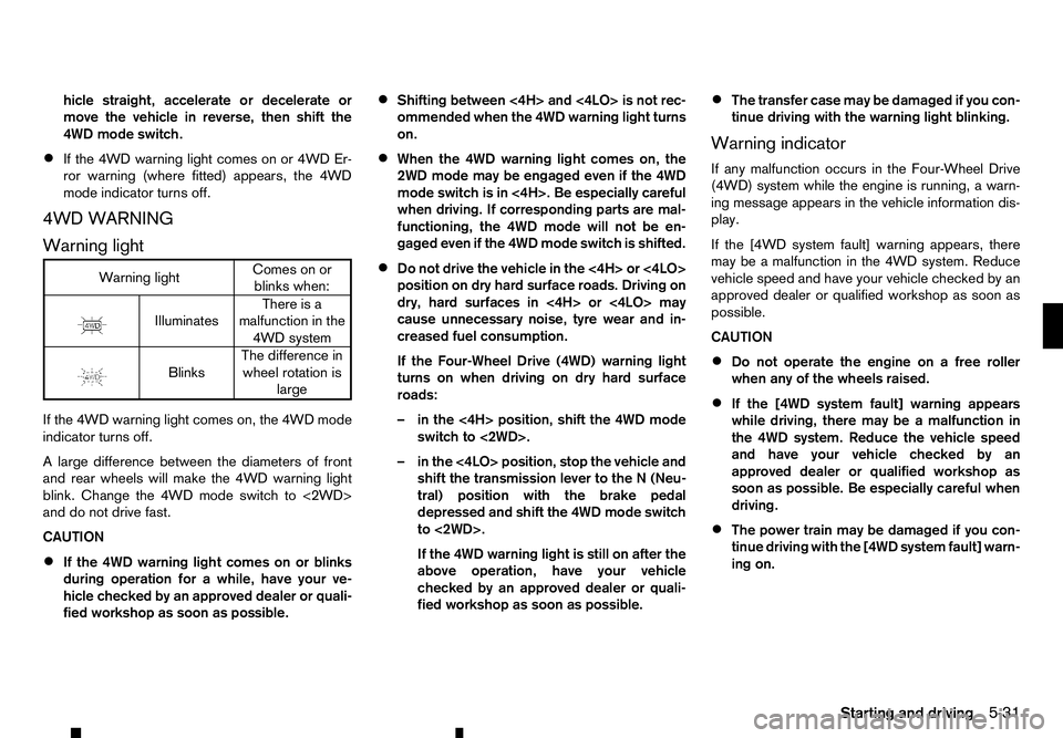
Warning light Warning light
Comes on or
blinks when:
m Illuminates
There
is a
malfunction in the
4WD system
m Blinks
The
difference in
wheel rotation is large
If the 4WD warning light comes on, the 4WD mode
indicator turns off.
Al arge difference between the diameters of front
and rear wheels will make the 4WD warning light
blink. Change the 4WD mode switch to <2WD>
and do not drive fast.
CAUTION
• If the 4WD warning light comes on or blinks
during operation for
awhile, have your ve-
hicle checked by an approved dealer or quali-
fied workshop as soon as possible. •
Shifting between <4H> and <4LO> is not rec-
ommended when the 4WD warning light turns
on.
• When the 4WD warning light comes on, the
2WD mode may be engaged even if the 4WD
mode switch is in <4H>. Be especially careful
when driving. If corresponding parts are mal-
functioning, the 4WD mode will not be en-
gaged even if the 4WD mode switch is shifted.
• Do not drive the vehicle in the <4H> or <4LO>
position on dry hard surface roads. Driving on
dry, hard surfaces in <4H> or <4LO> may
cause unnecessary noise, tyre wear and in-
creased fuel consumption.
If the Four-Wheel Drive (4WD) warning light
turns on when driving on dry hard surface
roads:
–i nthe <4H> position, shift the 4WD mode
switch to <2WD>.
–i nthe <4LO> position, stop the vehicle and
shift the transmission lever to the N(Neu-
tral) position with the brake pedal
depressed and shift the 4WD mode switch
to <2WD>.
If the 4WD warning light is still on after the
above operation, have your vehicle
checked by an approved dealer or quali-
fied workshop as soon as possible. •
The transfer case may be damaged if you con-
tinue driving with the warning light blinking.
Warning indicator
If any malfunction occurs in the Four-Wheel Drive
(4WD) system while the engine is running, awarn-
ing message appears in the vehicle information dis-
play.
If the [4WD system fault] warning appears, there
may be amalfunction in the 4WD system. Reduce
vehicle speed and have your vehicle checked by an
approved dealer or qualified workshop as soon as
possible.
CAUTION
• Do not operate the engine on
afree roller
when any of the wheels raised.
• If the [4WD system fault] warning appears
while driving, there may be
amalfunction in
the 4WD system. Reduce the vehicle speed
and have your vehicle checked by an
approved dealer or qualified workshop as
soon as possible. Be especially careful when
driving.
• The power train may be damaged if you con-
tinue driving with the [4WD system fault] warn-
ing on.
Starting and driving 5-31
Page 234 of 340
TYRE RECOMMENDATION FOR 4WD
CAUTION
• Always use tyres of the same size, brand, con-
struction (bias, bias-belted or radial), and
tread pattern on all four wheels. Failure to do
so may result in acircumference difference
between tyres on the front and rear axles,
which will cause excessive tyre wear and may damage the transmission, transfer case and
differential gears.
• ONLY use spare tyres specified for the Four-
Wheel Drive (4WD) models.
If excessive tyre wear is found, it is recommended
that all four tyres be replaced with tyres of the same
size, brand, construction and tread pattern. The tyre
pressure and wheel alignment should also be
checked and corrected as necessary. Contact an
approved dealer or qualified workshop.
Snow tyres
If you install snow tyres, they must also be of the
same size, brand, construction and tread pattern on
all four wheels.
Tyre inflation pressure
Periodically check the pressures of all tyres, includ-
ing the spare, with agauge while at aservice sta-
tion. If necessary, adjust to the specified pressure.
Tyre pressures are shown on the tyre placard af-
fixed to the driver’s side centre pillar or rear access
door. Tyre rotation
RENAULT recommends that tyres should be rotated
every 5,000 km (3,000 miles).
Snow chains
Snow chains must be installed only on the rear
wheels and not on the front wheels.
Do not drive with snow chains on paved roads that are clear of snow. Driving with chains in such condi-
tions can cause damage to the various mechanisms of the vehicle due to overstress. When driving on
clear paved roads, be sure to change to Two-Wheel
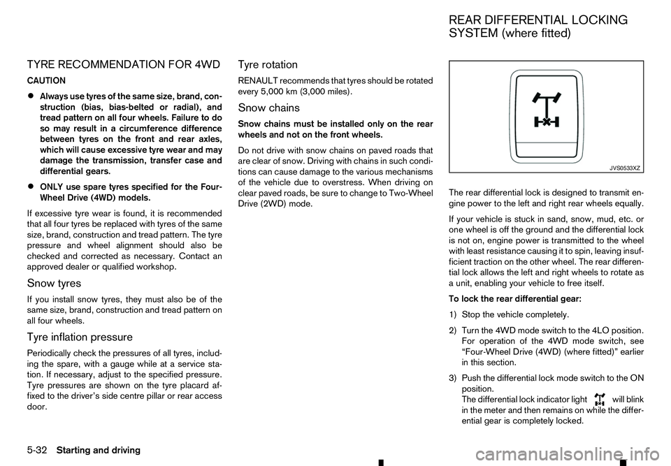
Drive (2WD) mode. The rear differential lock is designed to transmit en-
gine power to the left and right rear wheels equally.
If your vehicle is stuck in sand, snow, mud, etc. or
one wheel is off the ground and the differential lock
is not on, engine power is transmitted to the wheel
with least resistance causing it to spin, leaving insuf-
ficient traction on the other wheel. The rear differen-
tial lock allows the left and right wheels to rotate as
au
nit, enabling your vehicle to free itself.
To lock the rear differential gear:
1) Stop the vehicle completely.
2) Turn the 4WD mode switch to the 4LO position. For operation of the 4WD mode switch, see
“Four-Wheel Drive (4WD) (where fitted)” earlier
in this section.
3) Push the differential lock mode switch to the ON position.
The differential lock indicator light will blink
in the meter and then remains on while the differ-
ential gear is completely locked. JVS0533XZ
REAR DIFFERENTIAL LOCKING
SYSTEM (where fitted)
5-32 Starting and driving
Page 238 of 340
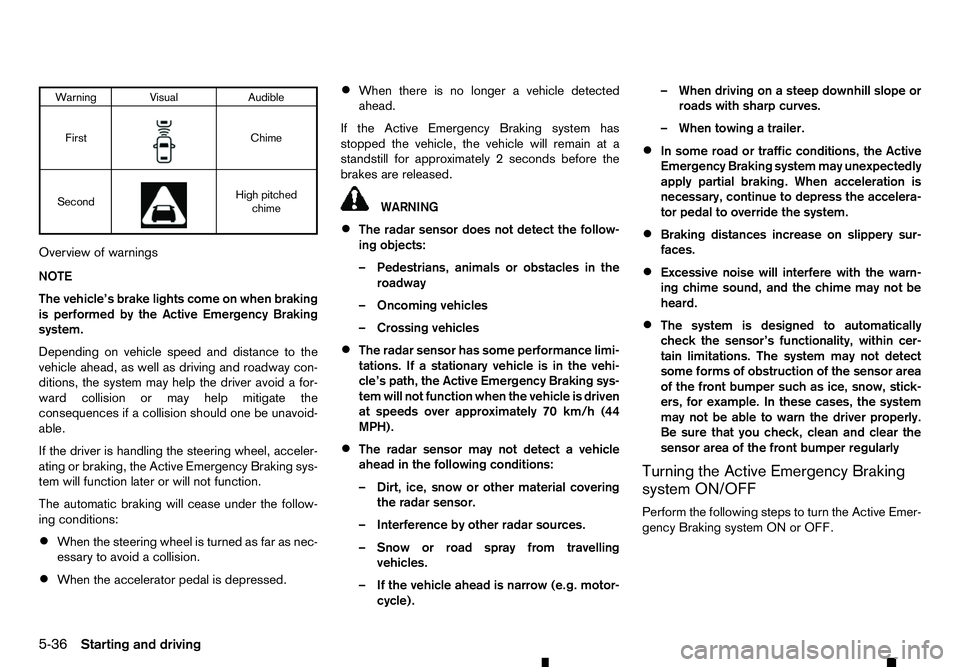
Warning Visual
Audible
First m Chime
Second m High pitched
chime
Overview of warnings
NOTE
The vehicle’s brake lights come on when braking
is performed by the Active Emergency Braking
system.
Depending on vehicle speed and distance to the
vehicle ahead, as well as driving and roadway con-
ditions, the system may help the driver avoid afor-
ward collision or may help mitigate the
consequences if acollision should one be unavoid-
able.
If the driver is handling the steering wheel, acceler-
ating or braking, the Active Emergency Braking sys-
tem will function later or will not function.
The automatic braking will cease under the follow-
ing conditions:
• When the steering wheel is turned as far as nec-
essary to avoid acollision.
• When the accelerator pedal is depressed. •
When there is no longer
avehicle detected
ahead.
If the Active Emergency Braking system has
stopped the vehicle, the vehicle will remain at a
standstill for approximately 2seconds before the
brakes are released. WARNING
• The radar sensor does not detect the follow-
ing objects:
–P edestrians, animals or obstacles in the
roadway
–O ncoming vehicles
–C rossing vehicles
• The radar sensor has some performance limi-
tations. If
astationary vehicle is in the vehi-
cle’s path, the Active Emergency Braking sys-
tem will not function when the vehicle is driven
at speeds over approximately 70 km/h (44
MPH).
• The radar sensor may not detect
avehicle
ahead in the following conditions:
–D irt, ice, snow or other material covering
the radar sensor.
–I nterference by other radar sources.
–S now or road spray from travelling
vehicles.
–I fthe vehicle ahead is narrow (e.g. motor-
cycle). –W
hen driving on asteep downhill slope or
roads with sharp curves.
–W hen towing atrailer.
• In some road or traffic conditions, the Active
Emergency Braking system may unexpectedly
apply partial braking. When acceleration is
necessary, continue to depress the accelera-
tor pedal to override the system.
• Braking distances increase on slippery sur-
faces.
• Excessive noise will interfere with the warn-
ing chime sound, and the chime may not be
heard.
• The system is designed to automatically
check the sensor’s functionality, within cer-
tain limitations. The system may not detect
some forms of obstruction of the sensor area
of the front bumper such as ice, snow, stick-
ers, for example. In these cases, the system
may not be able to warn the driver properly.
Be sure that you check, clean and clear the
sensor area of the front bumper regularly
Turning the Active Emergency Braking
system ON/OFF
Perform the following steps to turn the Active Emer-
gency Braking system ON or OFF.
5-36 Starting and driving
Page 240 of 340
WARNING
• Never rely solely on the hill descent control
system to control vehicle speed when driving
on steep downhill grades. Always drive care-
fully when using the hill descent control sys-
tem and decelerate the vehicle speed by de- pressing the brake pedal if necessary. Be
especially careful when driving on frozen,
muddy or extremely steep downhill roads.
Failure to control vehicle speed may result in
al oss of control of the vehicle and possible
serious injury or death.
• The hill descent control system may not con-
trol the vehicle speed on
ahill under all load
or road conditions. Always be prepared to de-
press the brake pedal to control vehicle
speed. Failure to do so may result in acolli-
sion or serious personal injury.
When the hill descent control system is activated, it
automatically applies smooth brakes to control
speed on asteep and slippery descent or off the
road without brake or accelerator operation. The hill
descent control system helps maintain vehicle speed
when driving under 25 km/h (16 MPH) on asteep
descent that engine braking alone in the <4H> or
<4LO> mode cannot control the speed.
NOTE
When the hill descent control system operates
continuously for along time, the temperature of
the Electronic Stability Programme (ESP) system
actuator may increase and the hill descent con- trol system may be temporarily disabled. The hill
descent control system on indicator light will turn
off. The hill descent control system will resume
operating automatically and the indicator light
will illuminate again when the temperature of the
ESP system actuator is reduced. If the indicator
light does not illuminate, turn off the system.
HILL DESCENT CONTROL SWITCH
When additional braking is required on steep down-
hill roads, activate the hill descent control system by
pushing the hill descent control switch on.
When the hill descent control system is activated,
the hill descent control system on indicator light will
illuminate. (See “Warning lights, indicator lights and audible reminders” in the “2. Instruments and
controls” section.) Also, the stop/tail lights illumi-
nate while the hill descent control system is applying
the brakes to control the vehicle speed. To activate the hill descent control system, satisfy all
of the following conditions:
• Shift the transmission to the forward (only 1st
gear for MT model) or reverse gear.
• Shift the 4WD mode switch to the <4H> or
<4LO> position and drive the vehicle at
aspeed
under 25 km/h (16 MPH).
See “Warning lights, indicator lights and audible
reminders” in the “2. Instruments and controls”
section.
• Push the hill descent control switch to the “ON”
position.
If the accelerator or brake pedal is depressed while
the hill descent control system is on, the system will
stop operating temporarily. As soon as the accel- erator or brake pedal is released, the hill descent
control system begins to function again if the hill
descent control operating conditions are fulfilled.
The hill descent control system on indicator light
blinks if the hill descent control switch is on and all
conditions for system activation are not met, or if the
system becomes disengaged for any reason.
To turn off the hill descent control system, push the
hill descent control switch to the “OFF” position. JVS0402XZ
HILL DESCENT CONTROL
SYSTEM (where fitted)
5-38 Starting and driving
Page 241 of 340
WARNING
• Never rely solely on the hill start assist system
to prevent the vehicle from moving backward on ahill. Always drive carefully and attentively.
Depress the brake pedal when the vehicle is
stopped on asteep hill. Be especially careful
when stopped on ahill on frozen or muddy
roads. Failure to prevent the vehicle from roll-
ing backwards may result in aloss of control
of the vehicle and possible serious injury or
death.
• The hill start assist system is not designed to
hold the vehicle at
astandstill on ahill. De-
press the brake pedal when the vehicle is
stopped on asteep hill. Failure to do so may
cause the vehicle to roll backwards and may
result in acollision or serious personal injury.
• The hill start assist system may not prevent
the vehicle from rolling backwards on ahill
under all load or road conditions. Always be
prepared to depress the brake pedal to pre-
vent the vehicle from rolling backwards. Fail-
ure to do so may result in acollision or seri-
ous personal injury.
The hill start assist system automatically keeps the
brakes applied to help prevent the vehicle from roll-
ing backwards in the time it takes the driver to re-
lease the brake pedal and apply the accelerator
when the vehicle is stopped on ahill. The hill start assist system will operate automatically
under the following conditions:
• The transmission is shifted to
aforward or re-
verse gear.
• The vehicle is stopped completely on
ahill by
applying the brake.
The maximum holding time is 2seconds. After 2
seconds the vehicle will begin to roll back and the
hill start assist system will stop operating completely.
The hill start assist system will not operate when the
transmission is shifted to the N(Neutral) or P(Park)
position or on aflat and level road.
When the Electronic Stability Programme (ESP)
warning light illuminates in the meter, the hill start
assist system will not operate. (See “Electronic Sta-
bility Programme (ESP) system (where fitted)” ear-
lier in this section.) The cruise control system allows driving at constant
speeds without keeping your foot on the accelerator
pedal. WARNING
• The cruise control system ONLY maintains a
constant vehicle speed, it does not replace
the driver.
• Always observe the posted speed limits and
do not set the speed over them.
• Do not use the cruise control when driving
under the following conditions. Doing so
could cause
aloss of vehicle control and re-
sult in an accident.
–W hen it is not possible to keep the vehicle
at ac onstant speed
–W hen driving in heavy traffic
–W hen driving in traffic that varies speed
–W hen driving in windy areas
–W hen driving on winding or hilly roads
–W hen driving on slippery (rain, snow, ice,
etc.) roads
CAUTION
On manual Transmission (MT) model, do not shift
to the N(Neutral) position without depressing
the clutch pedal when the cruise control is oper-
HILL START ASSIST SYSTEM
(where fitted)
CRUISE CONTROL (where fitted)
Starting and driving 5-39
Page 245 of 340
When the speed limit is set, the speed limiter sym-
bol ➃and the set speed value
➄will illuminate in
the vehicle information display. The limiter symbol
will turn green.
Changing aspeed limit
Use either of the following operations to change an
active speed limit:
• Push and release the
j Au pwards or
Each time you do this, the set speed will in-
crease or decrease by 1km/h (1 MPH).
• Push and hold the
j Au pwards or
The set speed will increase or decrease to the
next multiple of 5km/h (5 MPH) and then in
steps of 5km/h (5 MPH).
The new set speed limit value ➄will be displayed
in the vehicle information display.
When the actual vehicle speed exceeds the set
speed, an audible warning will be heard ashort time
after the set speed is exceeded and driver interven- tion is not detected.
Cancelling aspeed limit
To cancel aset speed limit, push the
switch ➀.T
he speed limiter symbol
➃and the set
speed value ➄in the vehicle information display
will be turned off.
It is also possible to override the speed limiter by
fully depressing the accelerator pedal beyond the
resistance point. WARNING
• The vehicle may accelerate when the speed
limiter cancels.
• When additional floor mats are used, be sure
that they are correctly secured and that they
cannot interfere with the accelerator pedal.
Mats not adapted to the vehicle may prevent
proper operation of the speed limiter.
Fully depress the accelerator pedal beyond the re-
sistance point. The speed limiter will be suspended
to allow driving above the set speed. The set speed
value ➄will flash and an audible warning will sound.
The speed limiter will automatically resume when
the vehicle speed drops below the set speed limit.
Resuming aprevious set speed
If as et speed limit has been cancelled, the set speed
will be stored in the speed limiter memory.
This speed limit can be reactivated by pressing the
Au pwards.
If the current vehicle speed is higher than the previ-
ous set speed, the accelerator pedal will not work
and the set speed value ➄will flash until the vehicle
speed drops below the set speed limit.
When the actual vehicle speed exceeds the set
speed, an audible warning will be heard ashort time
after the set speed is exceeded and driver interven- tion is not detected. Turning the speed limiter off
The speed limiter system will be turned off when
one of the following operations is performed:
•
Push the speed limiter main “ON/OFF” switch
➂ .T
he speed limiter symbol
➃and the set
speed value ➄in the vehicle information display
will be turned off.
• Push the cruise control main “ON/OFF” switch
➁ .T
he speed limiter information in the vehicle
information will be replaced with the cruise con-
trol information. For details see “Cruise control
(where fitted)” earlier in this section.
• When the vehicle is stopped and the ignition is
turned to the off position.
Turning off the speed limiter will erase the set
speed limit memory.
Speed limiter malfunction
If the speed limiter malfunctions, the speed limiter
symbol ➃in the vehicle information display will
flash.
Turn the speed limiter off by pushing the speed lim-
iter main “ON/OFF” switch ➂and have the system
checked by an approved dealer or qualified work-
shop.
Starting and driving 5-43
Page 246 of 340
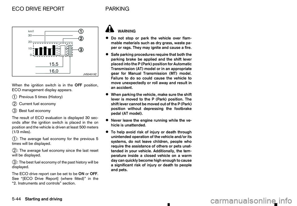
When the ignition switch is in the
OFFposition,
ECO management display appears.
➀ Previous
5times (History)
➁ Current fuel economy
➂ Best fuel economy
The result of ECO evaluation is displayed 30 sec-
onds after the ignition switch is placed in the on
position and the vehicle is driven at least 500 meters
(1/3 miles).
➀ :T
he average fuel economy for the previous 5
times will be displayed.
➁ :T
he average fuel economy since the last reset
will be displayed.
➂ :T
he best fuel economy of the past history will be
displayed.
The ECO drive report can be set to be ONorOFF.
See “[ECO Drive Report] (where fitted)” in the
“2. Instruments and controls” section. WARNING
• Do not stop or park the vehicle over flam-
mable materials such as dry grass, waste pa-
per or rags. They may ignite and cause afire.
• Safe parking procedures require that both the
parking brake be applied and the shift lever
placed into the
P(Park) position for Automatic
Transmission (AT) model or in an appropriate
gear for Manual Transmission (MT) model.
Failure to do so could cause the vehicle to
move unexpectedly or roll away and result in
an accident.
• When parking the vehicle, make sure the shift
lever is moved to the
P(Park) position. The
shift lever cannot be moved out of the P(Park)
position without depressing the footbrake
pedal (AT model).
• Never leave the engine running while the ve-
hicle is unattended.
• To help avoid risk of injury or death through
unintended operation of the vehicle and/or its systems, do not leave children, people who
require the assistance of others or pets unat-
tended in your vehicle. Additionally, the tem-
perature inside aclosed vehicle on awarm
day can quickly become high enough to cause
as ignificant risk of injury or death to people
and pets. JVS0451XZ
ECO DRIVE REPORT
PARKING
5-44 Starting and driving
Page 248 of 340

The parking sensor (sonar) system sounds
atone to
inform the driver of obstacles near the bumper.
When the “Display” key is ON, the sensor view will
automatically appear in the vehicle information dis-
play. WARNING
• The parking sensor (sonar) system is
aconve-
nience but it is not asubstitute for proper
parking. The driver is always responsible for
safety during parking and other manoeuvres.
Always look around and check that it is safe
to do so before parking.
• Read and understand the limitations of the
parking sensor (sonar) system as contained
in this section. The colours of the corner sen-
sor indicator and the distance guide lines in
the rear view indicate different distances to
the object. Inclement weather or ultrasonic
sources such as an automatic car wash, a truck’s compressed-air brakes, or
apneu-
matic drill may affect the function of the sys-
tem; this may include reduced performance
or afalse activation.
• This function is designed as an aid to the driver
in detecting large stationary objects to help
avoid damaging the vehicle. The system is
not designed to prevent contact with small or
moving objects. Always move slowly.
• The system will not detect small objects be-
low the bumper, and may not detect objects
close to the bumper or on the ground.
• The system may not detect the following ob-
jects.
–F
luffy objects such as snow, cloth, cotton,
glass-wool, etc.
–T hin objects such as rope, wire, chain, etc.
–W edge-shaped objects •
If your vehicle sustains damage to the bumper
fascia, leaving it misaligned or bent, the sens-
ing zone may be altered causing inaccurate
measurement of obstacles or false alarms.
CAUTION
• Keep the interior of the vehicle as quiet as
possible to hear the tone clearly.
• Keep the sensors (located on the bumper fas-
cia) free from snow, ice, and large accumula-
tions of dirt. Do not clean the sensors with
sharp objects. If the sensors are covered, the
accuracy of the sensor function will be dimin-
ished.
The system informs with visual and audible signals
of rear obstacles when the shift lever is in the R
(Reverse) position.
The system is deactivated at speeds above 10 km/h
(6 MPH). It is reactivated at lower speeds.
The intermittent tone will stop after 3seconds when
an obstacle is detected only by acorner sensor and
the distance does not change. The tone will stop
when the obstacle moves away from the vehicle. JVS0532XZ
PARKING SENSOR (SONAR) SYSTEM (where fitted)
5-46 Starting and driving
Page 250 of 340
Your new vehicle was designed to be used primarily
to carry passengers and luggage.
Towing atrailer will place additional loads on your
vehicle’s engine, drive train, steering, braking and
other systems. The towing of atrailer will exagger-
ate other conditions such as sway caused by cross-
winds, rough road surfaces or passing trucks.
Your driving style and speed must be adjusted ac-
cording to the circumstances. Before towing a
trailer, see an approved dealer or qualified work-
shop for an explanation about the proper use of tow-
ing equipment.
OPERATING PRECAUTIONS
• Avoid towing
atrailer during the running-in pe-
riod.
• Before driving, make sure that the lighting sys-
tem of the trailer works properly.
• Observe the legal maximum speeds for trailer
operation.
• Avoid abrupt starts, accelerations and stops.
• Avoid sharp turns and lane changes.
• Always drive your vehicle at
amoderate speed.
• Follow the trailer manufacturer’s instructions.
• Choose proper coupling devices (trailer hitch,
safety chain, roof carrier, etc.) for your vehicle
and trailer. These devices are available from an
approved dealer or qualified workshop where
you can also obtain more detailed information
about trailer towing. •
Never allow the total trailer load (trailer weight
plus its cargo weight) to exceed the maximum
set for the vehicle and the coupling device. See
an approved dealer or qualified workshop for
more information.
• The trailer must be loaded so that heavy goods
are placed over the axle. The maximum allowable
vertical load on the trailer hitch must not be ex-
ceeded.
• Have your vehicle serviced more often than at
the intervals specified in
aseparate maintenance
booklet.
• Trailer towing requires more fuel than under nor-
mal circumstances because of
aconsiderable
increase in traction power and resistance.
While towing atrailer, check the engine coolant
temperature indicator to prevent the vehicle from
overheating.
TYRE PRESSURE
When towing atrailer, inflate the vehicle tyres to the
maximum recommended COLD tyre pressure (for
full loading) indicated on the tyre placard.
Do not tow atrailer when the vehicle is installed with
at emporary spare tyre or acompact spare tyre.
SAFETY CHAINS
Always use asuitable chain between the vehicle
and trailer. The chain should be crossed and should
be attached to the hitch, not to the vehicle bumper
or axle. Be sure to leave enough slack in the chain
to permit turning corners. TRAILER BRAKES
Ensure that trailer brakes are installed as required
by local regulations. Also check that all other trailer
equipment conforms to local regulations.
Always block the wheels on both the vehicle and
trailer when parking. Apply the hand brake on the
trailer where fitted. Parking on
asteep slope is not
recommended.
If parking on asteep slope is unavoidable, place the
shift lever in the P(Park) position (Automatic trans-
mission model), or in an appropriate position
(Manual transmission model), and turn the front
wheels towards the kerb.
TRAILER DETECTION (where fitted)
When towing atrailer with agenuine RENAULT tow
bar electrical kit and the turn signal switch is used,
the electrical system of the vehicle will detect the
additional electrical load of the trailer lighting. As a
result, the direction indicator tone will be different.
TRAILER TOWING
5-48
Starting and driving