door lock RENAULT ALASKAN 2017 Owners Manual
[x] Cancel search | Manufacturer: RENAULT, Model Year: 2017, Model line: ALASKAN, Model: RENAULT ALASKAN 2017Pages: 340, PDF Size: 6.93 MB
Page 9 of 340
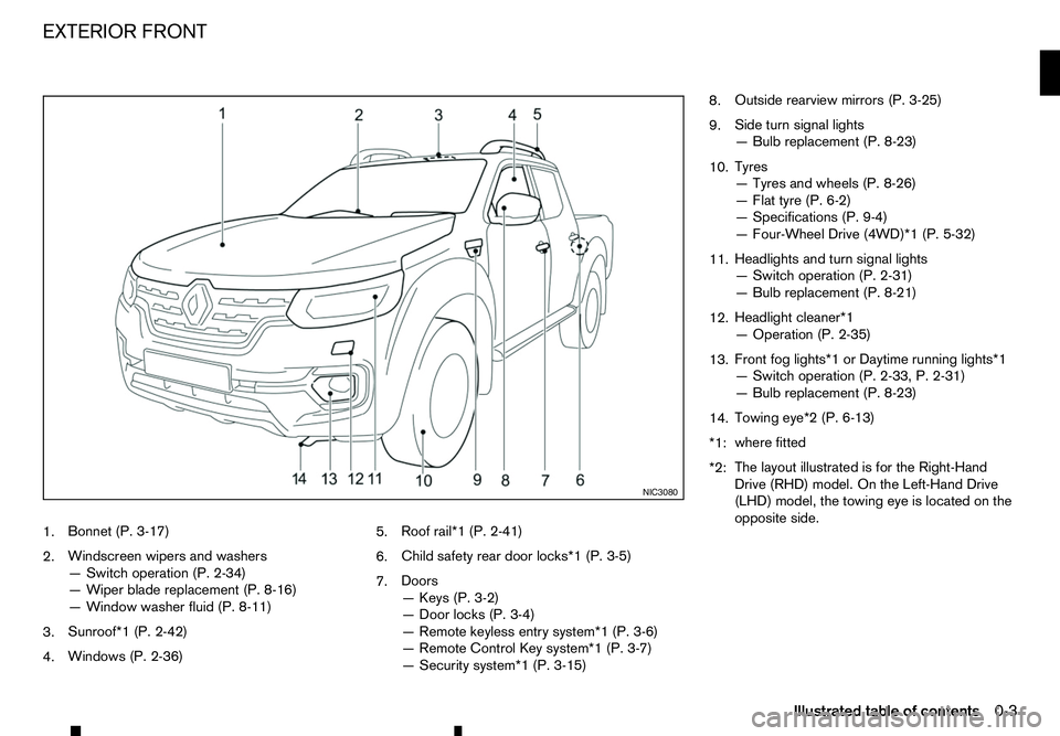
1.
Bonnet (P. 3-17)
2. Windscreen wipers and washers
—S
witch operation (P. 2-34)
—W iper blade replacement (P. 8-16)
—W indow washer fluid (P. 8-11)
3. Sunroof*1 (P. 2-42)
4. Windows (P. 2-36) 5.
Roof rail*1 (P. 2-41)
6. Child safety rear door locks*1 (P. 3-5)
7. Doors
—K
eys (P. 3-2)
—D oor locks (P. 3-4)
—R emote keyless entry system*1 (P. 3-6)
—R emote Control Key system*1 (P. 3-7)
—S ecurity system*1 (P. 3-15) 8.
Outside rearview mirrors (P. 3-25)
9. Side turn signal lights
—B
ulb replacement (P. 8-23)
10. Tyres
—T
yres and wheels (P. 8-26)
—F lat tyre (P. 6-2)
—S pecifications (P. 9-4)
—F our-Wheel Drive (4WD)*1 (P. 5-32)
11. Headlights and turn signal lights
—S
witch operation (P. 2-31)
—B ulb replacement (P. 8-21)
12. Headlight cleaner*1
—O
peration (P. 2-35)
13. Front fog lights*1 or Daytime running lights*1
—S
witch operation (P. 2-33, P. 2-31)
—B ulb replacement (P. 8-23)
14. Towing eye*2 (P. 6-13)
*1: where fitted
*2: The layout illustrated is for the Right-Hand
Drive (RHD) model. On the Left-Hand Drive
(LHD) model, the towing eye is located on the
opposite side. NIC3080
EXTERIOR FRONT
Illustrated table of contents0-3
Page 11 of 340

1.
Inside rearview mirror (P. 3-23)
2. Sunglasses holder* (P. 2-40)
3. Microphone*
—B
luetooth® Hands-Free Phone System*
(P. 4-59, P. 4-65)
4. Sunroof switch* (P. 2-42)
5. Map lights (P. 2-43) 6.
Sun visors (P. 2-41)
7. Room light* (P. 2-44)
8. Rear personal light* (P. 2-45)
9. Console box* (P. 2-40)
—P
ower outlet (P. 2-38)
10. Cup holders* (P. 2-40) 11.
Door armrest
—P
ower window controls* (P. 2-36)
—P ower door lock switch (driver’s door)*
(P. 3-4)
—O utside rearview mirror remote control
switch (driver’s door)* (P. 3-25)
*: where fitted NIC2792
PASSENGER COMPARTMENT
Illustrated table of contents0-5
Page 14 of 340
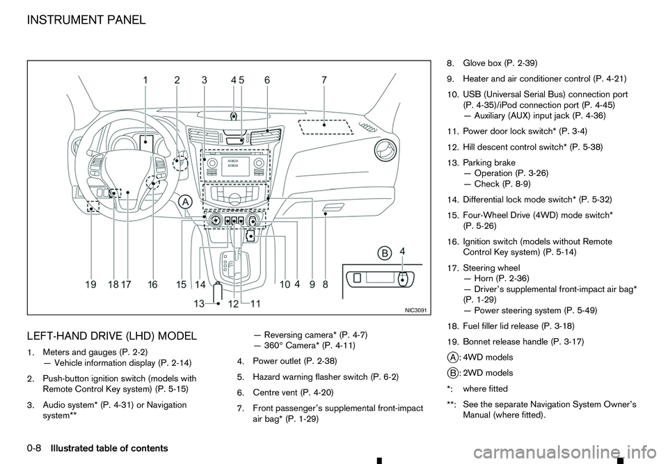
LEFT-HAND DRIVE (LHD) MODEL
1. Meters and gauges (P. 2-2)
—V ehicle information display (P. 2-14)
2. Push-button ignition switch (models with
Remote Control Key system) (P. 5-15)
3. Audio system* (P. 4-31) or Navigation
system** —R
eversing camera* (P. 4-7)
—3 60° Camera* (P. 4-11)
4. Power outlet (P. 2-38)
5. Hazard warning flasher switch (P. 6-2)
6. Centre vent (P. 4-20)
7. Front passenger’s supplemental front-impact
air bag* (P. 1-29) 8.
Glove box (P. 2-39)
9. Heater and air conditioner control (P. 4-21)
10. USB (Universal Serial Bus) connection port
(P. 4-35)/iPod connection port (P. 4-45)
—A
uxiliary (AUX) input jack (P. 4-36)
11. Power door lock switch* (P. 3-4)
12. Hill descent control switch* (P. 5-38)
13. Parking brake
—O
peration (P. 3-26)
—C heck (P. 8-9)
14. Differential lock mode switch* (P. 5-32)
15. Four-Wheel Drive (4WD) mode switch*
(P. 5-26)
16. Ignition switch (models without Remote
Control Key system) (P. 5-14)
17. Steering wheel
—H
orn (P. 2-36)
—D river’s supplemental front-impact air bag*
(P. 1-29)
—P ower steering system (P. 5-49)
18. Fuel filler lid release (P. 3-18)
19. Bonnet release handle (P. 3-17)
j A: 4WD models
j B: 2WD models
*: where fitted
**: See the separate Navigation System Owner’s
Manual (where fitted). NIC3091
INSTRUMENT PANEL
0-8 Illustrated table of contents
Page 15 of 340
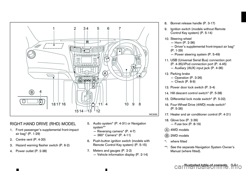
RIGHT-HAND DRIVE (RHD) MODEL
1. Front passenger’s supplemental front-impact
air bag* (P. 1-29)
2. Centre vent (P. 4-20)
3. Hazard warning flasher switch (P. 6-2)
4. Power outlet (P. 2-38) 5.
Audio system* (P. 4-31) or Navigation
system**
—R
eversing camera* (P. 4-7)
—3 60° Camera* (P. 4-11)
6. Push-button ignition switch (models with
Remote Control Key system) (P. 5-15)
7. Meters and gauges (P. 2-2)
—V
ehicle information display (P. 2-14) 8.
Bonnet release handle (P. 3-17)
9. Ignition switch (models without Remote
Control Key system) (P. 5-14)
10. Steering wheel
—H
orn (P. 2-36)
—D river’s supplemental front-impact air bag*
(P. 1-29)
—P ower steering system (P. 5-49)
11. USB (Universal Serial Bus) connection port
(P. 4-35)/iPod connection port (P. 4-45)
—A
uxiliary (AUX) input jack (P. 4-36)
12. Parking brake
—O
peration (P. 3-26)
—C heck (P. 8-9)
13. Power door lock switch (P. 3-4)
14. Hill descent control switch* (P. 5-38)
15. Differential lock mode switch* (P. 5-32)
16. Four-Wheel Drive (4WD) mode switch*
(P. 5-26)
17. Heater and air conditioner control (P. 4-21)
18. Glove box (P. 2-39)
—F
use box (P. 8-19)
j A: 4WD models
j B: 2WD models
*: where fitted
**: See the separate Navigation System Owner’s
Manual (where fitted). NIC3092
Illustrated table of contents
0-9
Page 63 of 340
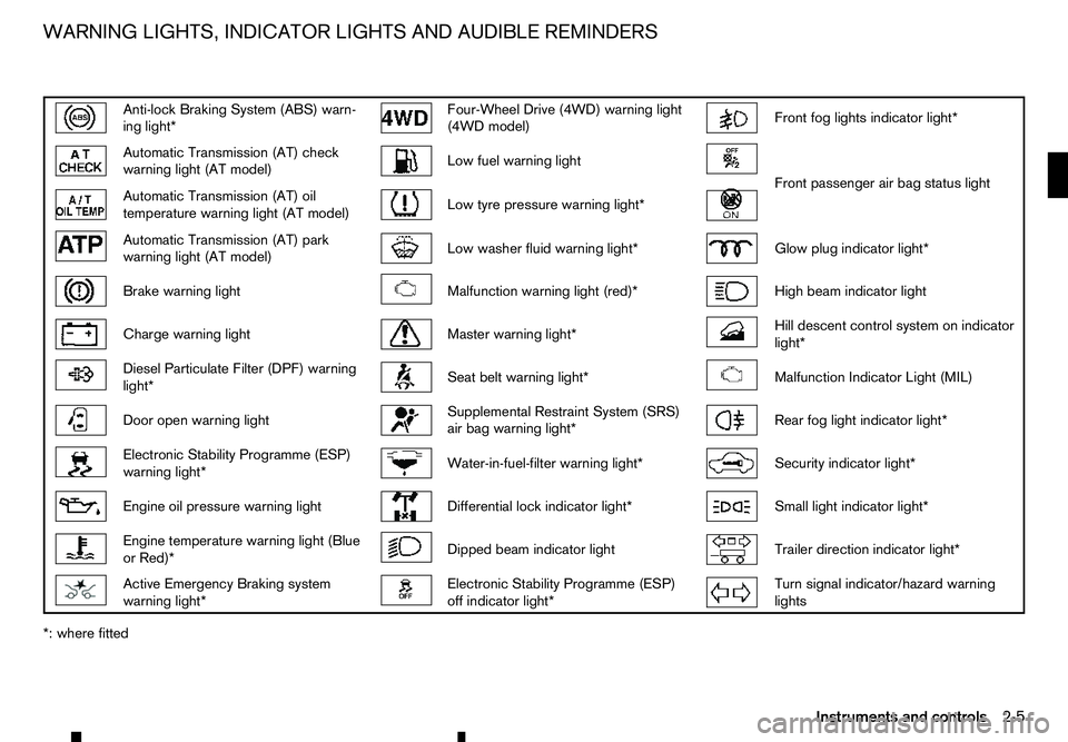
Anti-lock Braking System (ABS) warn-
ing light* Four-Wheel Drive (4WD) warning light
(4WD model) Front fog lights indicator light*
Automatic Transmission (AT) check
warning light (AT model) Low fuel warning light
Front passenger air bag status light
Automatic Transmission (AT) oil
temperature warning light (AT model) Low tyre pressure warning light*
Automatic Transmission (AT) park
warning light (AT model) Low washer fluid warning light*
Glow plug indicator light*
Brake warning light
Malfunction warning light (red)*
High beam indicator light
Charge warning light
Master warning light*
Hill descent control system on indicator
light* Diesel Particulate Filter (DPF) warning
light* Seat belt warning light*
Malfunction Indicator Light (MIL)
Door open warning light
Supplemental Restraint System (SRS)
air bag warning light* Rear fog light indicator light*
Electronic Stability Programme (ESP)
warning light* Water-in-fuel-filter warning light*
Security indicator light*
Engine oil pressure warning light
Differential lock indicator light*
Small light indicator light*
Engine temperature warning light (Blue
or Red)* Dipped beam indicator light
Trailer direction indicator light*
Active Emergency Braking system
warning light* Electronic Stability Programme (ESP)
off indicator light* Turn signal indicator/hazard warning
lights
*: where fitted WARNING LIGHTS, INDICATOR LIGHTS AND AUDIBLE REMINDERS
Instruments and controls2-5
Page 64 of 340
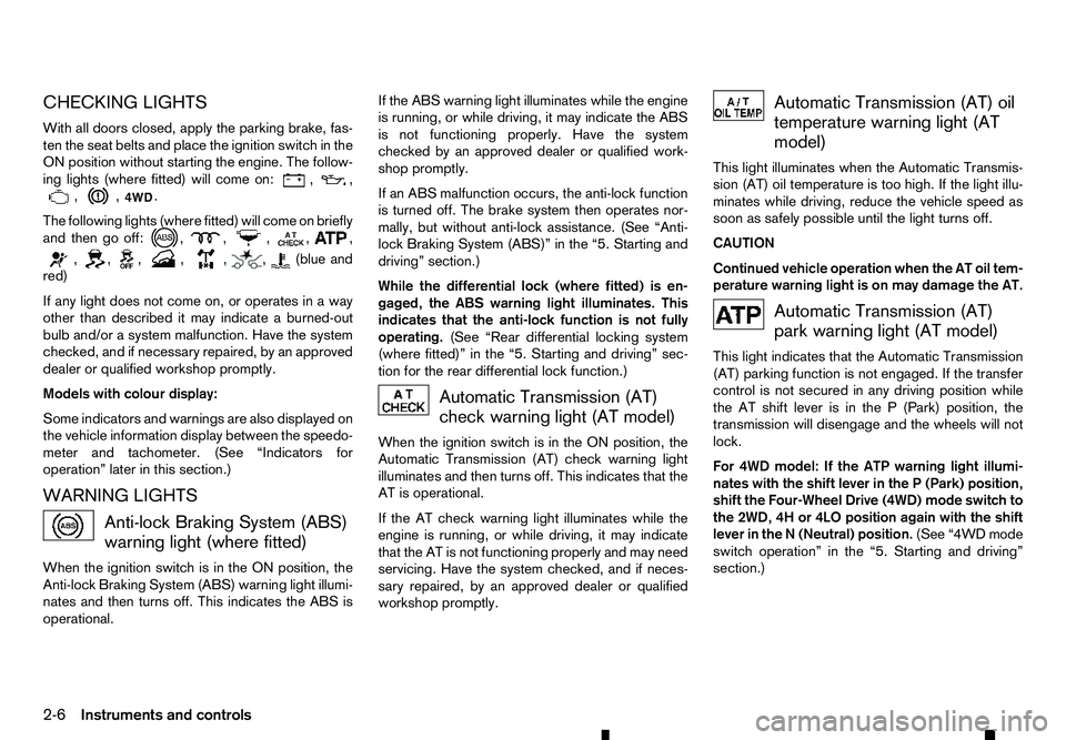
CHECKING LIGHTS
With all doors closed, apply the parking brake, fas-
ten the seat belts and place the ignition switch in the
ON position without starting the engine. The follow-
ing lights (where fitted) will come on: , ,
, , .
The following lights (where fitted) will come on briefly
and then go off: , , ,
, ,
, , , , , , (blue and
red)
If any light does not come on, or operates in away
other than described it may indicate aburned-out
bulb and/or asystem malfunction. Have the system
checked, and if necessary repaired, by an approved
dealer or qualified workshop promptly.
Models with colour display:
Some indicators and warnings are also displayed on
the vehicle information display between the speedo-
meter and tachometer. (See “Indicators for
operation” later in this section.)
WARNING LIGHTS Anti-lock Braking System (ABS)
warning light (where fitted)
When the ignition switch is in the ON position, the
Anti-lock Braking System (ABS) warning light illumi- nates and then turns off. This indicates the ABS is
operational. If the ABS warning light illuminates while the engine
is running, or while driving, it may indicate the ABS
is not functioning properly. Have the system
checked by an approved dealer or qualified work-
shop promptly.
If an ABS malfunction occurs, the anti-lock function
is turned off. The brake system then operates nor-
mally, but without anti-lock assistance. (See “Anti-
lock Braking System (ABS)” in the “5. Starting and
driving” section.)
While the differential lock (where fitted) is en-
gaged, the ABS warning light illuminates. This
indicates that the anti-lock function is not fully
operating. (See “Rear differential locking system
(where fitted)” in the “5. Starting and driving” sec-
tion for the rear differential lock function.) Automatic Transmission (AT)
check warning light (AT model)
When the ignition switch is in the ON position, the
Automatic Transmission (AT) check warning light
illuminates and then turns off. This indicates that the
AT is operational.
If the AT check warning light illuminates while the
engine is running, or while driving, it may indicate
that the AT is not functioning properly and may need
servicing. Have the system checked, and if neces-
sary repaired, by an approved dealer or qualified
workshop promptly. Automatic Transmission (AT) oil
temperature warning light (AT
model)
This light illuminates when the Automatic Transmis-
sion (AT) oil temperature is too high. If the light illu-
minates while driving, reduce the vehicle speed as
soon as safely possible until the light turns off.
CAUTION
Continued vehicle operation when the AT oil tem-
perature warning light is on may damage the AT. Automatic Transmission (AT)
park warning light (AT model)
This light indicates that the Automatic Transmission
(AT) parking function is not engaged. If the transfer
control is not secured in any driving position while
the AT shift lever is in the P(Park) position, the
transmission will disengage and the wheels will not
lock.
For 4WD model: If the ATP warning light illumi-
nates with the shift lever in the P(Park) position,
shift the Four-Wheel Drive (4WD) mode switch to
the 2WD, 4H or 4LO position again with the shift
lever in the N(Neutral) position. (See “4WD mode
switch operation” in the “5. Starting and driving”
section.)
2-6 Instruments and controls
Page 72 of 340
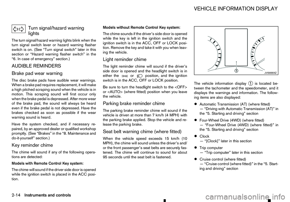
Turn signal/hazard warning
lights
The turn signal/hazard warning lights blink when the
turn signal switch lever or hazard warning flasher
switch is on. (See “Turn signal switch” later in this
section or “Hazard warning flasher switch” in the
“6. In case of emergency” section.)
AUDIBLE REMINDERS
Brake pad wear warning The disc brake pads have audible wear warnings.
When abrake pad requires replacement, it will make
ah igh pitched scraping sound when the vehicle is in
motion. This scraping sound will first occur only
when the brake pedal is depressed. After more wear
of the brake pad, the sound will always be heard
even if the brake pedal is not depressed. Have the
brakes checked as soon as possible if the wear
warning sound is heard.
Have the system checked, and if necessary re-
paired, by an approved dealer or qualified workshop
promptly. (See “Brakes” in the “8. Maintenance and
do-it-yourself” section.)
Key reminder chime
The chime will sound if any of the following opera-
tions are detected:
Models with Remote Control Key system:
The chime will sound if the driver side door is opened
while the ignition switch is placed in the ACC posi-
tion. Models without Remote Control Key system:
The chime sounds if the driver’s side door is opened
while the key is left in the ignition switch and the
ignition switch is in the ACC, OFF or LOCK posi-
tion. Remove the key and take it with you when leav-
ing the vehicle.
Light reminder chime
The light reminder chime will sound if the driver’s
side door is opened and the headlight switch is in
either the or position, and the ignition
switch is in the ACC, OFF or LOCK position.
Be sure to turn the headlight switch to the
or
the vehicle.
Parking brake reminder chime
The parking brake reminder chime will sound if the
vehicle is driven at more than 7km/h (4 MPH) with
the parking brake applied. Stop the vehicle and re-
lease the parking brake.
Seat belt warning chime (where fitted)
When the vehicle speed exceeds 15 km/h (10
MPH), the chime will sound unless the driver’s and/
or the front passenger’s seat belts are securely fas-
tened. The chime will continue to sound for about
95 seconds until the seat belt is fastened. The vehicle information display
➀is located be-
tween the tachometer and the speedometer, and it
displays the warnings and information. The follow-
ing items are also displayed:
• Automatic Transmission (AT) (where fitted)
—“
Driving with Automatic Transmission (AT)” in
the “5. Starting and driving” section
• Four-Wheel Drive (4WD) (where fitted)
—“
Four-Wheel Drive (4WD) (where fitted)” in
the “5. Starting and driving” section
• Clock
—“
[Clock]” later in this section
• Trip computer
—“
Trip computer” later in this section
• Cruise control (where fitted)
—“
Cruise control (where fitted)” in the “5. Start-
ing and driving” section JVI0899XZ
VEHICLE INFORMATION DISPLAY
2-14 Instruments and controls
Page 75 of 340
![RENAULT ALASKAN 2017 Owners Manual [Display Settings]
The following sub-menus are available under the
[Display Settings] menu.
• [Contents Selection]
• [Body Colour]
• [ECO Drive Report] (where fitted)
• [Welcome Effect]
[Conte RENAULT ALASKAN 2017 Owners Manual [Display Settings]
The following sub-menus are available under the
[Display Settings] menu.
• [Contents Selection]
• [Body Colour]
• [ECO Drive Report] (where fitted)
• [Welcome Effect]
[Conte](/img/7/58394/w960_58394-74.png)
[Display Settings]
The following sub-menus are available under the
[Display Settings] menu.
• [Contents Selection]
• [Body Colour]
• [ECO Drive Report] (where fitted)
• [Welcome Effect]
[Contents Selection]:
Select this sub-menu to enable/disable the items
that are displayed.
• [Home]
• [Average Speed]
• [Trip]
• [Fuel Economy]
• [Navigation] (where fitted)
• [Audio]
• [Driving Aids] (where fitted)
• [Tyre Pressures] (where fitted)
[Body Colour]:
In this sub-menu you can change the colour of the
vehicle displayed in the vehicle information display. [ECO Drive Report] (where fitted):
There are
2items in the [ECO Drive Report] menu.
• [Display]
Select this item to enable/disable the ECO Drive
Report in the vehicle information display.
• [View History]
Select this sub-menu to show the fuel economy
history, current economy, and the best fuel
economy. See, “ECO drive report” in the
“5. Starting and driving” section.
–[ Back] will return you to the [ECO Drive Re-
port] menu.
–[ Reset] will reset the fuel economy history to
zero.
[Welcome Effect]:
Select this sub-menu to enable/disable the items
described below to ONorOFF.
• [Dial and Pointer]
The indicator needles sweep in the meters when
the engine is started.
• [Display Effect]
The welcome screen display appears when the
ignition is placed in the
ONposition. [Vehicle Settings]
The following sub-menus are available under the
[Vehicle Settings] menu.
•
[Lighting]
• [Turn Indicator]
• [Unlocking]
• [Wipers]
[Lighting] (where fitted):
There are 2items under the Lighting menu.
• [Int. Lamp Timer]
Select this item to enable/disable the interior
lamp timer feature.
The interior lights will be
ONif any door is un-
locked when the interior lamp timer is enabled.
• [Auto Lights]
The automatic lighting system can be set to illu-
minate earlier or later based on the brightness
outside the vehicle. See, “Headlight and turn sig-
nal switch” in the “2. Instruments and controls”
section.
–[
On Earliest]
–[ On Earlier]
–[ Standard]
–[ On Later]
Instruments and controls 2-17
Page 76 of 340
![RENAULT ALASKAN 2017 Owners Manual [Turn Indicator]:
Select this sub-menu to enable/disable the items
described below to ONorOFF.
• [3 Flash On]
Select this sub-menu to enable/disable the [3
Flash On] lane change signal feature. See, RENAULT ALASKAN 2017 Owners Manual [Turn Indicator]:
Select this sub-menu to enable/disable the items
described below to ONorOFF.
• [3 Flash On]
Select this sub-menu to enable/disable the [3
Flash On] lane change signal feature. See,](/img/7/58394/w960_58394-75.png)
[Turn Indicator]:
Select this sub-menu to enable/disable the items
described below to ONorOFF.
• [3 Flash On]
Select this sub-menu to enable/disable the [3
Flash On] lane change signal feature. See, “Turn
signal switch” in the “2. Instruments and
controls” section.
[Unlocking] (where fitted):
Select this sub-menu to enable/disable the items
described below to ONorOFF.
• [I-Key Door Lock]
Select this item to activate/deactivate the request
switch on the door. See, “Doors” in the “3. Pre-
driving checks and adjustments” section.
[Wipers]:
Select this sub-menu to enable/disable the items
described below to ONorOFF.
• [Speed Dependent]
Select this item to activate/deactivate the speed
dependent wiper speed feature. See, “Wiper
and washer switch” in the “2. Instruments and
controls” section.
[Maintenance]
The following sub-menus are available under the
[Maintenance] menu.
• [Service] •
[Filter]
• [Tyre]
• [Other]
[Service] (where fitted):
Select this item to show the remaining distance until
servicing is required.
To reset the service indicator, push
select [Yes].
The distance to service interval cannot be adjusted
manually. The interval is set automatically.
NOTE
Be sure the distance to service indicator is reset
after servicing. Otherwise, the service indicator
will continue to be displayed.
[Filter] (where fitted):
Select this item to set or reset the distance for re-
placing the oil filter.
The distance can be set from [———](off) to
30.000 km in 500 km increments.
[Tyre]:
Select this item to set or reset the distance for re-
placing the tyres.
The distance can be set from [———](off) to
30.000 km in 500 km increments. [Other]:
Select this item to set or reset
areminder for replac-
ing something other than service, the oil filter, or
tyres.
The distance can be set from [———](off) to
30.000 km in 500 km increments.
[Alert]
The following items are available under the [Alert]
menu.
• [Timer]
• [Navigation] (where fitted)
• [Phone] (where fitted)
• [Mail] (where fitted)
[Timer]:
Select this sub-menu to specify when the [Time for
ad river break?] message activates.
The time can be set from [———](off) to6hours
in increments of 30 minutes.
[Navigation] (where fitted):
Select this item to enable/disable the navigation sys-
tem information in the vehicle information display.
[Phone] (where fitted):
Select this item to enable/disable incoming call in-
formation in the vehicle information display.
[Mail] (where fitted):
Select this item to enable/disable incoming mail in-
formation in the vehicle information display.
2-18 Instruments and controls
Page 84 of 340
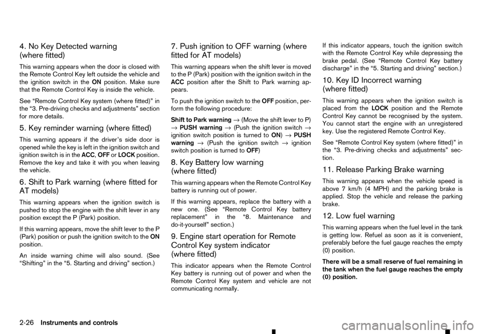
4. No Key Detected warning
(where fitted)
This warning appears when the door is closed with
the Remote Control Key left outside the vehicle and
the ignition switch in the ONposition. Make sure
that the Remote Control Key is inside the vehicle.
See “Remote Control Key system (where fitted)” in
the “3. Pre-driving checks and adjustments” section
for more details.
5. Key reminder warning (where fitted)
This warning appears if the driver’s side door is
opened while the key is left in the ignition switch and
ignition switch is in the ACC,OFForLOCK position.
Remove the key and take it with you when leaving
the vehicle.
6. Shift to Park warning (where fitted for
AT models)
This warning appears when the ignition switch is
pushed to stop the engine with the shift lever in any
position except the P(Park) position.
If this warning appears, move the shift lever to the P
(Park) position or push the ignition switch to the ON
position.
An inside warning chime will also sound. (See
“Shifting” in the “5. Starting and driving” section.) 7. Push ignition to OFF warning (where
fitted for AT models)
This warning appears when the shift lever is moved
to the
P(Park) position with the ignition switch in the
ACC position after the Shift to Park warning ap-
pears.
To push the ignition switch to the OFFposition, per-
form the following procedure:
Shift to Park warning →(Move the shift lever to P)
→ PUSH warning →(Push the ignition switch →
ignition switch position is turned to ON)→PUSH
warning →(Push the ignition switch →ignition
switch position is turned to OFF)
8. Key Battery low warning
(where fitted)
This warning appears when the Remote Control Key
battery is running out of power.
If this warning appears, replace the battery with a
new one. (See “Remote Control Key battery
replacement” in the “8. Maintenance and
do-it-yourself” section.)
9. Engine start operation for Remote
Control Key system indicator
(where fitted)
This indicator appears when the Remote Control
Key battery is running out of power and when the
Remote Control Key system and vehicle are not
communicating normally. If this indicator appears, touch the ignition switch
with the Remote Control Key while depressing the
brake pedal. (See “Remote Control Key battery
discharge” in the “5. Starting and driving” section.)
10. Key ID Incorrect warning
(where fitted)
This warning appears when the ignition switch is
placed from the LOCKposition and the Remote
Control Key cannot be recognised by the system.
You cannot start the engine with an unregistered
key. Use the registered Remote Control Key.
See “Remote Control Key system (where fitted)” in
the “3. Pre-driving checks and adjustments” sec-
tion.
11. Release Parking Brake warning
This warning appears when the vehicle speed is
above 7km/h (4 MPH) and the parking brake is
applied. Stop the vehicle and release the parking
brake.
12. Low fuel warning
This warning appears when the fuel level in the tank
is getting low. Refuel as soon as it is convenient,
preferably before the fuel gauge reaches the empty
(0) position.
There will be asmall reserve of fuel remaining in
the tank when the fuel gauge reaches the empty
(0) position.
2-26 Instruments and controls