fuse box RENAULT ALASKAN 2017 Owners Manual
[x] Cancel search | Manufacturer: RENAULT, Model Year: 2017, Model line: ALASKAN, Model: RENAULT ALASKAN 2017Pages: 340, PDF Size: 6.93 MB
Page 97 of 340
•
This power outlet is not designed for use with
ac igarette lighter unit.
• Do not use accessories that exceed
acom-
bined power draw of 12 volt, 120W (10A)
• Do not use double adapters or more than one
electrical accessory.
• Use this power outlet with the engine running
to avoid discharging the vehicle battery.
• Avoid using when the air conditioner, head-
lights or rear window defogger is on (where
fitted).
• Push the plug in as far as it will go. If good
contact is not made, the plug may overheat or the internal temperature fuse may blow.
• Before inserting or disconnecting
aplug, be
sure that the electrical accessory being used
is turned OFF.
• When not in use, be sure to close the cap. Do
not allow water or any liquid to contact the
outlet. WARNING
• The storage compartments should not be
used while driving so that the full attention
may be given to vehicle operation.
• Keep the storage lids closed while driving to
help prevent injury in an accident or
asudden
stop.
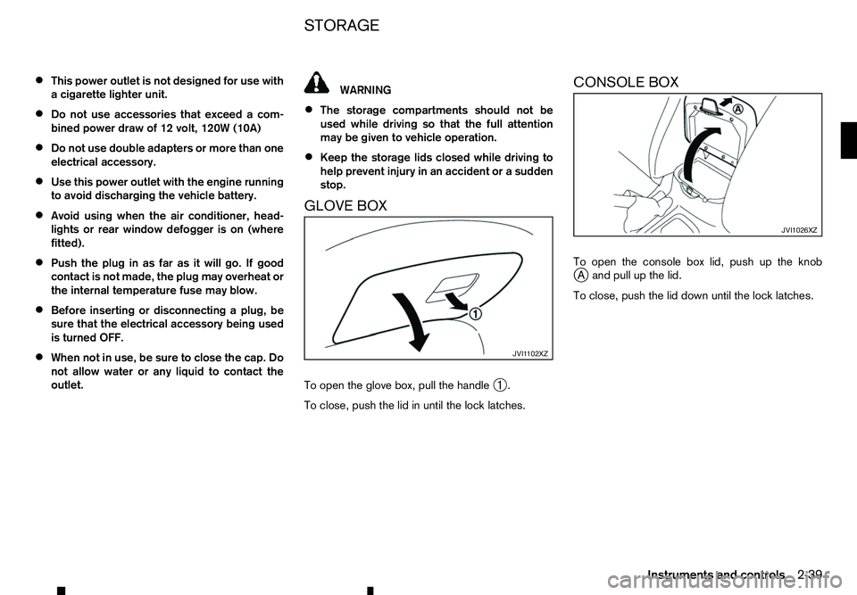
GLOVE BOX
To open the glove box, pull the handle ➀.
To close, push the lid in until the lock latches. CONSOLE BOX
To open the console box lid, push up the knob
j
Aa nd pull up the lid.
To close, push the lid down until the lock latches. JVI1 102XZ JVI1026XZ
STORAGE
Instruments and controls
2-39
Page 294 of 340
ENGINE COMPARTMENT
CAUTION
Never use afuse of ahigher or lower amperage
rating than that specified on the fuse box cover.
This could damage the electrical system or cause
af ire.
Never attempt to use other material (wire, alu-
minium foil. etc.) in place of afuse. This could
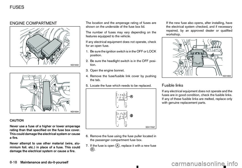
damage the electrical system or cause afire. The location and the amperage rating of fuses are
shown on the underside of the fuse box lid.
The number of fuses may vary depending on the
features equipped to the vehicle.
If any electrical equipment does not operate, check
for an open fuse.
1. Be sure the ignition switch is in the OFF or LOCK
position.
2. Be sure the headlight switch is in the OFF posi- tion.
3. Open the engine bonnet.
4. Remove the fuse/fusible link cover by pushing the tab.
5. Locate the fuse which needs to be replaced.
6. Remove the fuse using the fuse puller located in the passenger compartment fuse box.
7. If the fuse is open j
A, replace it with anew fuse
j B. If the new fuse also opens, after installing, have
the electrical system checked, and if necessary
repaired, by an approved dealer or qualified
workshop.
Fusible links
If any electrical equipment does not operate and the
fuses are in good condition, check the fusible links.
If any of these fusible links are melted, replace only
with genuine replacement parts. NDI1692
NDI1694
SDI1753Z NDI1693
FUSES
8-18
Maintenance and do-it-yourself
Page 295 of 340
PASSENGER COMPARTMENT
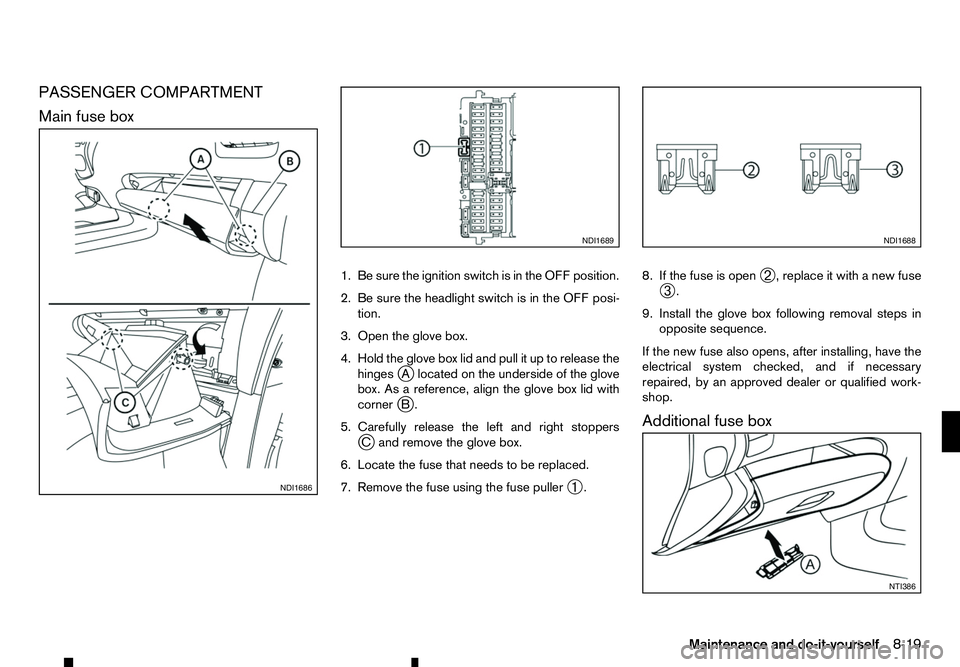
Main fuse box
1. Be sure the ignition switch is in the OFF position.
2. Be sure the headlight switch is in the OFF posi-tion.
3. Open the glove box.
4. Hold the glove box lid and pull it up to release the hinges jAl ocated on the underside of the glove
box. As areference, align the glove box lid with
corner jB.
5. Carefully release the left and right stoppers jCa nd remove the glove box.
6. Locate the fuse that needs to be replaced.
7. Remove the fuse using the fuse puller ➀. 8. If the fuse is open
➁,r
eplace it with anew fuse
➂ .
9. Install the glove box following removal steps in opposite sequence.
If the new fuse also opens, after installing, have the
electrical system checked, and if necessary
repaired, by an approved dealer or qualified work-
shop.
Additional fuse box NDI1686 NDI1689 NDI1688
NTI386
Maintenance and do-it-yourself
8-19
Page 296 of 340
1. Be sure the ignition switch is in the OFF position.
2. Be sure the headlight switch is in the OFF posi- tion.
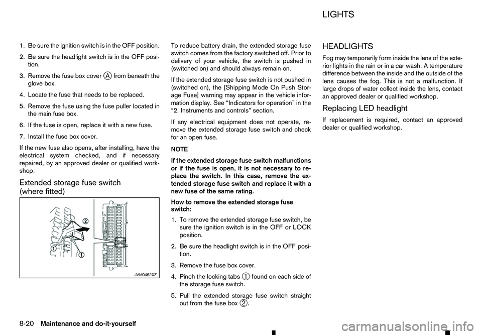
3. Remove the fuse box cover j
Af rom beneath the
glove box.
4. Locate the fuse that needs to be replaced.
5. Remove the fuse using the fuse puller located in the main fuse box.
6. If the fuse is open, replace it with anew fuse.
7. Install the fuse box cover.
If the new fuse also opens, after installing, have the
electrical system checked, and if necessary
repaired, by an approved dealer or qualified work-
shop.
Extended storage fuse switch
(where fitted) To reduce battery drain, the extended storage fuse
switch comes from the factory switched off. Prior to
delivery of your vehicle, the switch is pushed in
(switched on) and should always remain on.
If the extended storage fuse switch is not pushed in
(switched on), the [Shipping Mode On Push Stor-
age Fuse] warning may appear in the vehicle infor-
mation display. See “Indicators for operation” in the
“2. Instruments and controls” section.
If any electrical equipment does not operate, re-
move the extended storage fuse switch and check for an open fuse.
NOTE
If the extended storage fuse switch malfunctions
or if the fuse is open, it is not necessary to re-
place the switch. In this case, remove the ex- tended storage fuse switch and replace it with a
new fuse of the same rating.
How to remove the extended storage fuse
switch:
1. To remove the extended storage fuse switch, be sure the ignition switch is in the OFF or LOCK
position.
2. Be sure the headlight switch is in the OFF posi- tion.
3. Remove the fuse box cover.
4. Pinch the locking tabs ➀found on each side of
the storage fuse switch.
5. Pull the extended storage fuse switch straight out from the fuse box ➁. HEADLIGHTS
Fog may temporarily form inside the lens of the exte-
rior lights in the rain or in
acar wash. Atemperature
difference between the inside and the outside of the
lens causes the fog. This is not amalfunction. If
large drops of water collect inside the lens, contact
an approved dealer or qualified workshop.
Replacing LED headlight
If replacement is required, contact an approved
dealer or qualified workshop. JVM0462XZ LIGHTS
8-20 Maintenance and do-it-yourself
Page 326 of 340
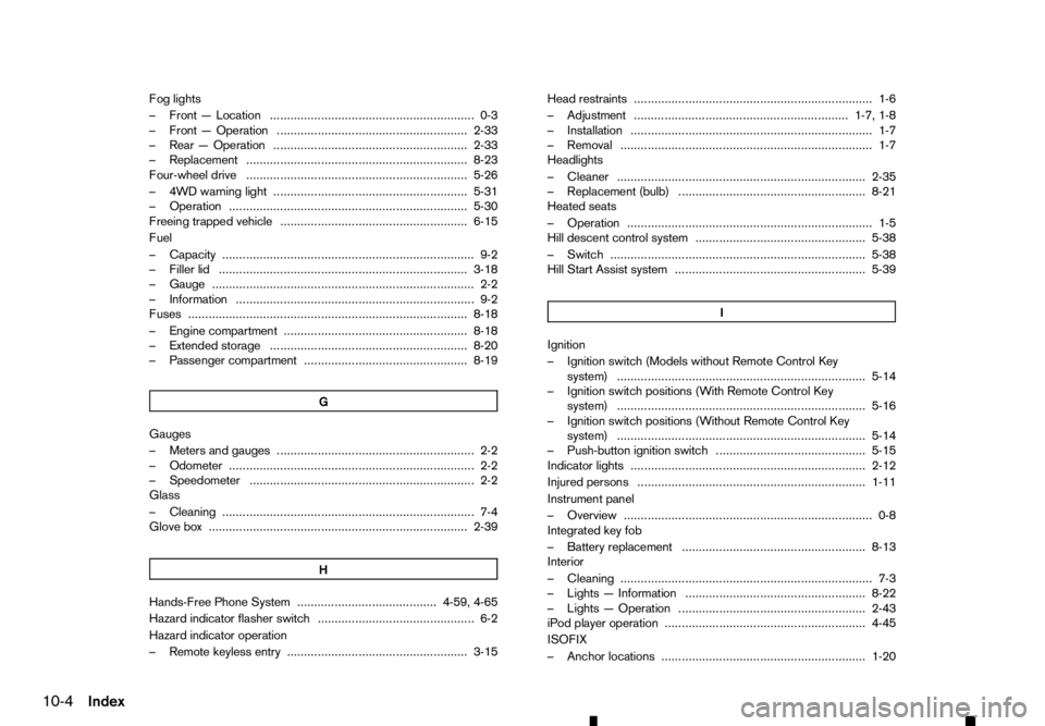
Fog lights
–F ront—Location ............................................................ 0-3
–F ront—O peration ........................................................ 2-33
–R ear—O peration ......................................................... 2-33
–R eplacement ................................................................. 8-23
Four-wheel drive ................................................................. 5-26
–4 WD warning light ......................................................... 5-31
–O peration ...................................................................... 5-30
Freeing trapped vehicle ....................................................... 6-15
Fuel
–C apacity ........................................................................V
.. 9-2
–F iller lid ........................................................................V
. 3-18
–G auge ........................................................................V
..... 2-2
–I nformation ...................................................................... 9-2
Fuses ........................................................................V
.......... 8-18
–E ngine compartment ...................................................... 8-18
–E xtended storage .......................................................... 8-20
–P assenger compartment ................................................ 8-19
G Gauges
–M
eters and gauges .......................................................... 2-2
–O dometer ........................................................................V
2-2
–S peedometer .................................................................. 2-2
Glass
–C leaning ........................................................................V
.. 7-4
Glove box ........................................................................V
.... 2-39
HHands-Free Phone System ......................................... 4-59, 4-65
Hazard indicator flasher switch .............................................. 6-2
Hazard indicator operation
–R emote keyless entry ..................................................... 3-15 Head restraints ...................................................................... 1-6
–A
djustment ............................................................... 1-7, 1-8
–I nstallation ....................................................................... 1-7
–R emoval ........................................................................V
.. 1-7
Headlights
–C leaner ........................................................................V
. 2-35
–R eplacement (bulb) ....................................................... 8-21
Heated seats
–O peration ........................................................................V
1-5
Hill descent control system .................................................. 5-38
–S witch ........................................................................V
... 5-38
Hill Start Assist system ........................................................ 5-39
I Ignition
–I
gnition switch (Models without Remote Control Key
system) ........................................................................V
. 5-14
–I gnition switch positions (With Remote Control Key
system) ........................................................................V
. 5-16
–I gnition switch positions (Without Remote Control Key
system) ........................................................................V
. 5-14
–P ush-button ignition switch ............................................ 5-15
Indicator lights ..................................................................... 2-12
Injured persons ................................................................... 1-11
Instrument panel
–O verview ........................................................................V
. 0-8
Integrated key fob
–B attery replacement ...................................................... 8-13
Interior
–C leaning ........................................................................V
.. 7-3
–L ights —Information ..................................................... 8-22
–L ights —Operation ....................................................... 2-43
iPod player operation ........................................................... 4-45
ISOFIX
–A nchor locations ............................................................ 1-20
10-4 Index