interior lights RENAULT ALASKAN 2017 Owners Manual
[x] Cancel search | Manufacturer: RENAULT, Model Year: 2017, Model line: ALASKAN, Model: RENAULT ALASKAN 2017Pages: 340, PDF Size: 6.93 MB
Page 59 of 340
2
Instruments and controls
Instruments and controls
Meters and gauges .................................................. 2-2 Speedometer and Fuel gauge ............................. 2-2
Tachometer and Engine coolant temperature
gauge ................................................................. 2-3
Instrument brightness control .............................. 2-4
Warning lights, indicator lights and audible
reminders ................................................................ 2-5 Checking lights................................................... 2-6
Warning lights .................................................... 2-6
Indicator lights .................................................... 2-12
Audible reminders............................................... 2-14
Vehicle information display ....................................... 2-14
How to use the Vehicle Information Display ......... 2-15
Settings .............................................................. 2-15
Trip computer ..................................................... 2-21
Indicators for operation ....................................... 2-25
Oil control system (where fitted for diesel
engine model) ..................................................... 2-29
Clock and outside air temperature (where
fitted).................................................................. 2-30
Headlight and turn signal switch............................... 2-31 Headlight switch ................................................. 2-31
Headlight aiming control (where fitted) ................ 2-32
Battery saver system (where fitted) ..................... 2-32
Turn signal switch ............................................... 2-32
Fog light switch (where fitted) .................................. 2-33
Front fog lights (where fitted) .............................. 2-33
Rear fog light (where fitted)................................. 2-33
Wiper and washer switch ........................................ 2-34 Windscreen wiper and washer switch ................. 2-34
Defogger switch (where fitted) ................................. 2-34
Headlight cleaner (where fitted) ............................... 2-35 Headlight cleaner switch (where fitted) ............... 2-35
Horn ........................................................................V
2-36
Windows ................................................................. 2-36 Manual windows (where fitted) ........................... 2-36
Power windows (where fitted)............................. 2-36
Power outlets .......................................................... 2-38
Storage ................................................................... 2-39 Glove box ........................................................... 2-39
Console box ....................................................... 2-40
Sunglasses holder .............................................. 2-40
Console side pockets ......................................... 2-40
Cup holders (where fitted) .................................. 2-40
Roof rail (where fitted) ........................................ 2-41
Card holder (where fitted)................................... 2-41
Sun visors ............................................................... 2-41
Sunroof (where fitted) .............................................. 2-42 Automatic sunroof............................................... 2-42
Interior lights ............................................................ 2-43 Interior light switch (where fitted) ........................ 2-43
Console light (where fitted) ................................. 2-43
Map lights........................................................... 2-43
Map light control switch (where fitted)................. 2-44
Room light (where fitted)..................................... 2-44
Rear personal light (where fitted) ........................ 2-45
Vanity mirror lights (where fitted) ......................... 2-45
Battery saver system........................................... 2-45
Page 75 of 340
![RENAULT ALASKAN 2017 Owners Manual [Display Settings]
The following sub-menus are available under the
[Display Settings] menu.
• [Contents Selection]
• [Body Colour]
• [ECO Drive Report] (where fitted)
• [Welcome Effect]
[Conte RENAULT ALASKAN 2017 Owners Manual [Display Settings]
The following sub-menus are available under the
[Display Settings] menu.
• [Contents Selection]
• [Body Colour]
• [ECO Drive Report] (where fitted)
• [Welcome Effect]
[Conte](/img/7/58394/w960_58394-74.png)
[Display Settings]
The following sub-menus are available under the
[Display Settings] menu.
• [Contents Selection]
• [Body Colour]
• [ECO Drive Report] (where fitted)
• [Welcome Effect]
[Contents Selection]:
Select this sub-menu to enable/disable the items
that are displayed.
• [Home]
• [Average Speed]
• [Trip]
• [Fuel Economy]
• [Navigation] (where fitted)
• [Audio]
• [Driving Aids] (where fitted)
• [Tyre Pressures] (where fitted)
[Body Colour]:
In this sub-menu you can change the colour of the
vehicle displayed in the vehicle information display. [ECO Drive Report] (where fitted):
There are
2items in the [ECO Drive Report] menu.
• [Display]
Select this item to enable/disable the ECO Drive
Report in the vehicle information display.
• [View History]
Select this sub-menu to show the fuel economy
history, current economy, and the best fuel
economy. See, “ECO drive report” in the
“5. Starting and driving” section.
–[ Back] will return you to the [ECO Drive Re-
port] menu.
–[ Reset] will reset the fuel economy history to
zero.
[Welcome Effect]:
Select this sub-menu to enable/disable the items
described below to ONorOFF.
• [Dial and Pointer]
The indicator needles sweep in the meters when
the engine is started.
• [Display Effect]
The welcome screen display appears when the
ignition is placed in the
ONposition. [Vehicle Settings]
The following sub-menus are available under the
[Vehicle Settings] menu.
•
[Lighting]
• [Turn Indicator]
• [Unlocking]
• [Wipers]
[Lighting] (where fitted):
There are 2items under the Lighting menu.
• [Int. Lamp Timer]
Select this item to enable/disable the interior
lamp timer feature.
The interior lights will be
ONif any door is un-
locked when the interior lamp timer is enabled.
• [Auto Lights]
The automatic lighting system can be set to illu-
minate earlier or later based on the brightness
outside the vehicle. See, “Headlight and turn sig-
nal switch” in the “2. Instruments and controls”
section.
–[
On Earliest]
–[ On Earlier]
–[ Standard]
–[ On Later]
Instruments and controls 2-17
Page 101 of 340
If the sunroof does not operate properly after per-
forming the procedure above, have your vehicle
checked by an approved dealer or qualified work-
shop. CAUTION
• Turn off the lights when you leave the vehicle.
• Do not use the lights for extended periods of
time with the engine stopped. This could re-
sult in
adischarged battery.
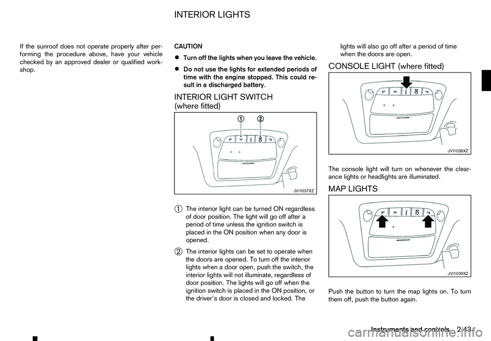
INTERIOR LIGHT SWITCH
(where fitted)
➀ The interior light can be turned ON regardless
of door position. The light will go off after a
period of time unless the ignition switch is
placed in the ON position when any door is
opened.
➁ The interior lights can be set to operate when
the doors are opened. To turn off the interior
lights when
adoor open, push the switch, the
interior lights will not illuminate, regardless of
door position. The lights will go off when the
ignition switch is placed in the ON position, or
the driver’s door is closed and locked. The lights will also go off after
aperiod of time
when the doors are open.
CONSOLE LIGHT (where fitted)
The console light will turn on whenever the clear-
ance lights or headlights are illuminated.
MAP LIGHTS
Push the button to turn the map lights on. To turn
them off, push the button again. JVI1037XZ JVI1038XZ
JVI1039XZ
INTERIOR LIGHTS
Instruments and controls2-43
Page 102 of 340
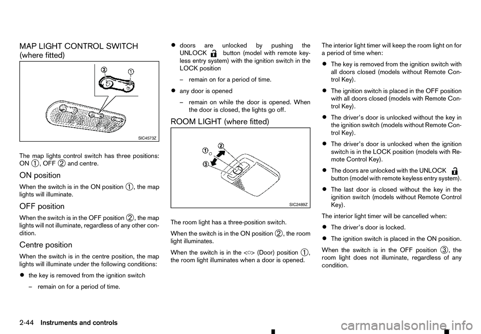
MAP LIGHT CONTROL SWITCH
(where fitted)
The map lights control switch has three positions:
ON ➀,O
FF
➁ and centre.
ON position
When the switch is in the ON position ➀,t
he map
lights will illuminate.
OFF position
When the switch is in the OFF position ➁,t
he map
lights will not illuminate, regardless of any other con-
dition.
Centre position
When the switch is in the centre position, the map
lights will illuminate under the following conditions:
• the key is removed from the ignition switch
–r emain on for aperiod of time. •
doors are unlocked by pushing the
UNLOCK button (model with remote key-
less entry system) with the ignition switch in the
LOCK position
–r emain on for aperiod of time.
• any door is opened
–r
emain on while the door is opened. When
the door is closed, the lights go off.
ROOM LIGHT (where fitted)
The room light has athree-position switch.
When the switch is in the ON position ➁,t
he room
light illuminates.
When the switch is in the
➀,
the room light illuminates when adoor is opened. The interior light timer will keep the room light on for
ap
eriod of time when:
• The key is removed from the ignition switch with
all doors closed (models without Remote Con-
trol Key).
• The ignition switch is placed in the OFF position
with all doors closed (models with Remote Con-
trol Key).
• The driver’s door is unlocked without the key in
the ignition switch (models without Remote Con-
trol Key).
• The driver’s door is unlocked when the ignition
switch is in the LOCK position (models with Re-
mote Control Key).
• The doors are unlocked with the UNLOCK button (model with remote keyless entry system).
• The last door is closed without the key in the
ignition switch (models without Remote Control
Key).
The interior light timer will be cancelled when:
• The driver’s door is locked.
• The ignition switch is placed in the ON position.
When the switch is in the OFF position ➂,t
he
room light does not illuminate, regardless of any
condition. SIC4573Z
SIC2489Z
2-44 Instruments and controls
Page 159 of 340
A/C (Air Conditioner) operation:
Push the A/Cbutton to turn on or off the air condi-
tioner. When the air conditioner is on, the A/Cindi-
cator light on the button illuminates.
Heater operation
Heating:
This mode is used to direct heated air from the foot
outlets.
1. Push the air recirculation button for normal
heating. (The indicator light will turn off.)
2. Push the button. (The indicator light will
turn on.)
3. Turn the fan speed control dial to the de-
sired position.
4. Turn the temperature control dial to the desired position between the middle and the hot (right)
position.
Defrosting or defogging:
This mode directs the air to the defogger outlets to
defrost/defog the windows.
1. Turn the fan speed control dial to the de-
sired position.
2. Push the front defogger button. (The indi-
cator lights on the front defogger button
and the
A/C button will turn on.) Then the air
recirculation indicator light will turn off. 3. Turn the temperature control dial to the desired
position between the middle and the hot (right)
position.
To remove frost from the windscreen quickly,
turn the temperature control dial to the maximum
hot (right) position and the fan speed control dial to the maximum position. For the best
bi-level heating performance, do not select the
air recirculation mode. For the best defogging
performance, do not select the air recirculation
mode.
Bi-level heating:
This mode directs cool air from the side/centre vents
and warm air from the foot outlets. (When the tem-
perature control dial is turned to the maximum hot
(right) or cool (left) position, the temperatures from
the side/centre vents and the foot outlets will be the
same.)
1. Push the air recirculation button. (The indi-
cator light will turn off.)
2. Push the button. (The indicator light will
turn on.)
3. Turn the fan speed control dial to the de-
sired position.
4. Turn the temperature control dial to the desired position. Heating and defogging:
This mode heats the interior and defogs the win-
dows.
1. Push the air recirculation button. (The indi-
cator light will turn off.)
2. Push the button. (The indicator light will
turn on.)
3. Turn the fan speed control dial to the de-
sired position.
4. Turn the temperature control dial to the maximum hot (right) position.
Air conditioner operation
The air conditioner system should be operated for
approximately 10 minutes at least once amonth.
This helps prevent damage to the air conditioner
system due to the lack of lubrication.
Cooling:
This mode is used to cool and dehumidify the air.
1. Push the air recirculation button. (The indi-
cator light will turn off.)
2. Push the button. (The indicator light will
turn on.)
3. Turn the fan speed control dial to the de-
sired position.
4. Push the A/Cbutton. (The indicator light will turn
on.)
Display screen, heater and air conditioner, and audio system 4-27
Page 277 of 340
8
Maintenance and do-it-yourself
Maintenance and do-it-yourself
Maintenance requirements ....................................... 8-2 Scheduled maintenance...................................... 8-2
General maintenance .......................................... 8-2
Where to go for service ...................................... 8-2
General maintenance ............................................... 8-2 Explanation of general maintenance items ........... 8-2
Maintenance precautions .................................... 8-4
Engine compartment check locations ....................... 8-5
Engine cooling system ............................................. 8-5 Checking engine coolant level............................. 8-6
Changing engine coolant .................................... 8-6
Engine oil................................................................. 8-6
Checking engine oil level .................................... 8-6
Changing engine oil and oil filter ......................... 8-7
Protect environment ............................................ 8-7
AdBlue® tank (where fitted for diesel engine
model) ..................................................................... 8-7 Refilling the AdBlue® tank .................................. 8-7
Drive belt ................................................................. 8-8
Automatic Transmission Fluid (ATF) (where fitted).... 8-8 7-speed Automatic Transmission (AT) model....... 8-8
Power steering fluid ................................................. 8-8
Brakes ..................................................................... 8-9 Checking parking brake ...................................... 8-9
Checking footbrake ............................................ 8-9
Brake booster ..................................................... 8-9
Brake fluid ............................................................... 8-10
Clutch fluid (where fitted) ......................................... 8-11 Window washer fluid ............................................... 8-11
Battery..................................................................... 8-12
Vehicle battery .................................................... 8-13
Remote controller battery (where fitted) .............. 8-13
Remote Control Key battery (where fitted)........... 8-14
Air cleaner filter........................................................ 8-15
Wiper blades ........................................................... 8-16 Windscreen wiper blades ................................... 8-16
Variable voltage control system (where fitted) ........... 8-17
Fuses ...................................................................... 8-18 Engine compartment ........................................... 8-18
Passenger compartment ..................................... 8-19
Lights ...................................................................... 8-20
Headlights .......................................................... 8-20
Exterior lights ...................................................... 8-21
Interior lights....................................................... 8-22
Light locations .................................................... 8-23
Tyres and wheels ..................................................... 8-26 Tyre inflation pressure......................................... 8-26
Types of tyres ..................................................... 8-26
Tyre chains ......................................................... 8-27
Tyre rotation ....................................................... 8-27
Tyre wear and damage ....................................... 8-28
Tyre age ............................................................. 8-28
Changing tyres and wheels................................. 8-28
Wheel balance.................................................... 8-28
Spare tyre .......................................................... 8-28
Page 298 of 340
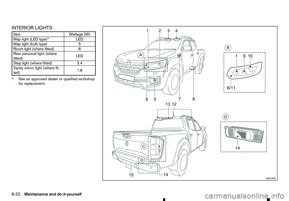
INTERIOR LIGHTS
Item
Wattage (W)
Map light (LED type)* LED
Map light (bulb type) 5
Room light (where fitted) 8
Rear personal light (where
fitted) LED
Step light (where fitted) 3.4
Vanity mirror light (where fit-
ted) 1.8
*: See an approved dealer or qualified workshop
for replacement. NDI1679
8-22 Maintenance and do-it-yourself
Page 326 of 340
Fog lights
–F ront—Location ............................................................ 0-3
–F ront—O peration ........................................................ 2-33
–R ear—O peration ......................................................... 2-33
–R eplacement ................................................................. 8-23
Four-wheel drive ................................................................. 5-26
–4 WD warning light ......................................................... 5-31
–O peration ...................................................................... 5-30
Freeing trapped vehicle ....................................................... 6-15
Fuel
–C apacity ........................................................................V
.. 9-2
–F iller lid ........................................................................V
. 3-18
–G auge ........................................................................V
..... 2-2
–I nformation ...................................................................... 9-2
Fuses ........................................................................V
.......... 8-18
–E ngine compartment ...................................................... 8-18
–E xtended storage .......................................................... 8-20
–P assenger compartment ................................................ 8-19
G Gauges
–M
eters and gauges .......................................................... 2-2
–O dometer ........................................................................V
2-2
–S peedometer .................................................................. 2-2
Glass
–C leaning ........................................................................V
.. 7-4
Glove box ........................................................................V
.... 2-39
HHands-Free Phone System ......................................... 4-59, 4-65
Hazard indicator flasher switch .............................................. 6-2
Hazard indicator operation
–R emote keyless entry ..................................................... 3-15 Head restraints ...................................................................... 1-6
–A
djustment ............................................................... 1-7, 1-8
–I nstallation ....................................................................... 1-7
–R emoval ........................................................................V
.. 1-7
Headlights
–C leaner ........................................................................V
. 2-35
–R eplacement (bulb) ....................................................... 8-21
Heated seats
–O peration ........................................................................V
1-5
Hill descent control system .................................................. 5-38
–S witch ........................................................................V
... 5-38
Hill Start Assist system ........................................................ 5-39
I Ignition
–I
gnition switch (Models without Remote Control Key
system) ........................................................................V
. 5-14
–I gnition switch positions (With Remote Control Key
system) ........................................................................V
. 5-16
–I gnition switch positions (Without Remote Control Key
system) ........................................................................V
. 5-14
–P ush-button ignition switch ............................................ 5-15
Indicator lights ..................................................................... 2-12
Injured persons ................................................................... 1-11
Instrument panel
–O verview ........................................................................V
. 0-8
Integrated key fob
–B attery replacement ...................................................... 8-13
Interior
–C leaning ........................................................................V
.. 7-3
–L ights —Information ..................................................... 8-22
–L ights —Operation ....................................................... 2-43
iPod player operation ........................................................... 4-45
ISOFIX
–A nchor locations ............................................................ 1-20
10-4 Index