Downloaded from www.Manualslib.com manuals search engine HEATING
Additional heating
61
61-6
MAINTENANCE
The principal maintenance operations on this
assembly are:
–replacing the ignition spark plug (5),
–cleaning the filter at the pump inlet (13) (see
page 61-2).
REMOVING - REFITTING COMPONENTS
FUEL PUMP INLET FILTER (13)
Remove the front bumper.
Rotate the pump (12) (see page 61-2) if it turns and
loosen the union covering the filter (13). Clean or
replace the filter if there is a combustion problem.
IGNITION SPARK PLUG
Disconnect and remove the heater without draining the
cooling circuit (use pliers Mot. 453-01).
Remove:
–the turbine cover (1),
–the control unit (9) and the cap (16),
–the spark plug (5) after disconnecting it.
FLAME DETECTOR
Disconnect and remove the heater without draining the
cooling circuit (use pliers Mot. 453-01).
Remove:
–the turbine cover (1),
–the control unit (9) and the cap (16).
Disconnect the flame connector by pulling the flat
terminals from the connector.
Remove the flame detector.
(WARNING: fragile part)COMBUSTION CHAMBER (4) AND EXCHANGER (3)
Remove:
–the flame detector and spark plug,
–the wiring harness fitted on the overheating
detector (8) and the temperature sensor (7),
–the turbine support (1).
Remove the combustion chamber (4) and the
exchanger (3) if necessary.
FAULT FINDING
In case of a fault, check:
–if there is fuel in the tank,
–if the fuses are intact
–if the pipes, connections and electrical unions are
intact,
–if the combustion air ducts or exhaust gas ducts are
blocked (unblock them if necessary).
In the even of combustion with the production of soot,
check:
–if the combustion air ducts or exhaust gas ducts are
blocked (unblock them if necessary),
–if there is a deposit in the exchanger (3) or the
combustion chamber (4); clean these if necessary,
–if the dosing pump flow is correct;
To do this:
●remove the bumper,
●disconnect the electric pump inlet fuel pipe (12),
from the side opposite the fuel filter (13),
●connect a pipe to the electric pump so that the flow
can be collected in a glass at the same height as
the heater,
●start the heater (if necessary, bridge the
temperature sensor located in front of the battery
screen). After approximately 40 seconds, the fuel
arrives and begins to bleed the circuit. Switch off
the ignition. Empty the glass and start again,
collecting the stabilised flow for approximately
30 seconds. Switch off the heater and measure the
quantity of fuel collected.
Normal flow: between 6.8 cm
3 and 7.8 cm3 for
90 seconds of operation.
Downloaded from www.Manualslib.com manuals search engine AIR CONDITIONING
Air conditioning compressor
62
62-1
662AIR CONDITIONING
Air conditioning compressor
The G9T engine vehicle is fitted with a variable
geometry air conditioning compressor; that is, the
compressor adapts the flow of refrigerant fluid
according to a difference in pressure between the
compressor inlet and outlet, and not according to the
temperature read by the sensor (omission of the
evaporator sensor).
The system cannot be adjusted
The pressure relief valve is still present but calibrated
differently.
REMOVAL
Put the vehicle on a 2 post lift.
Disconnect the battery.
Drain the refrigerant circuit (see special "AIR
CONDITIONING" manual).
Remove:
–the front right wheel,
–the right-hand wheel arch cover,
–the lower engine cover,
–the air exchanger/throttle body unit pipe after
disconnecting it,.
–the accessories belt (see methods in section 07
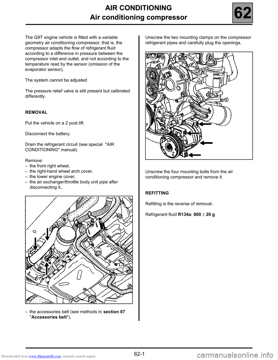
"Accessories belt"),Unscrew the two mounting clamps on the compressor
refrigerant pipes and carefully plug the openings.
Unscrew the four mounting bolts from the air
conditioning compressor and remove it.
REFITTING
Refitting is the reverse of removal.
Refrigerant fluid R134a: 800 ± 20 g


