steering RENAULT KANGOO 1997 KC / 1.G Chassis Workshop Manual
[x] Cancel search | Manufacturer: RENAULT, Model Year: 1997, Model line: KANGOO, Model: RENAULT KANGOO 1997 KC / 1.GPages: 105
Page 1 of 105
Chassis
GENERAL
FRONT AXLE
REAR AXLE
WHEELS AND TYRES
STEERING ASSEMBLY
MECHANICAL ELEMENT CONTROLS
ELECTRONICALLY CONTROLLED SYSTEMS
Renault 1997
77 11 194 253JULY 1997Edition Anglaise
"The repair methods given by the manufacturer in this document are based on the
technical specifications current when it was prepared.
The methods may be modified as a result of changes introduced by the
manufacturer in the production of the various component units and accessories
from which his vehicles are constructed."All copyrights reserved by Renault.
Copying or translating, in part or in full, of this document or use of the service part
reference numbering system is forbidden without the prior written authority of
Renault.
C
FC0A - FC0C - FC0D - FC0E - KC0A - KC0C - KC0D - KC0E
Page 4 of 105
Master cylinder
Brake servo
Air filter - Brake servo non-return
valve
Vacuum pump
Handbrake control lever
Handbrake control
Brake pipes
Braking compensator
Clutch control cable
Clutch automatic wear take-up
system
External gear control37-1
37-3
37-5
37-6
37-7
37-8
37-10
37-11
37-22
37-23
37-24
Contents
Page
MECHANICAL ELEMENT CONTROLS37
38-1
38-2
38-3
38-4
38-5
38-6
38-7
38-8
38-9
BOSCH ABS
Presentation of BOSCH ABS 5.3
Location of components
Presentation of the hydraulic
regulation assembly
Wiring diagram
Wiring diagram key
31 track connector
Diagnostic socket
Hydraulic assembly
Hydraulic braking test
ELECTRONICALLY CONTROLLED
HYDRAULIC SYSTEMS38STEERING ASSEMBLY
Axial ball joint
Manual steering rack
Power assisted steering rack
Gaiter
Steering rack pinion
Manual steering assistance pump
Steering column
36-1
36-3
36-4
36-6
36-7
36-8
36-12
36
Page 25 of 105
FRONT AXLE
Engine sub-frame
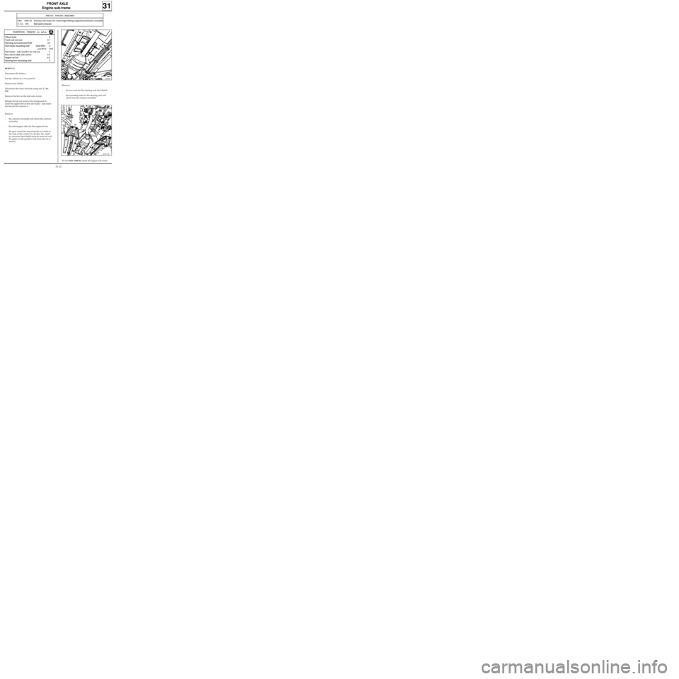
Remove:
- the two nuts for the steering rack heat shield,
- the mounting nuts for the steering rack and
attach it to the exhaust manifold.
31
12988R
SPECIAL TOOLING REQUIRED
Mot. 1040 -01 Dummy sub-frame for removing/refitting engine/transmission assembly
T. Av. 476 Ball joint extractor
REMOVAL
Disconnect the battery.
Put the vehicle on a two post lift.
Remove the wheels.
Disconnect the track rod ends using tool T. Av.
476.
Remove the key on the stub axle carrier.
Release but do not remove the mudguards to
reach the upper bolt on the sub-frame - side mem-
ber tie rod and remove it.
Remove:
- the exhaust downpipe and attach the catalytic
converter,
- the bolt (engine side) for the engine tie bar.
- the gear control by removing the two bolts at
the ends of the control. To do this, the cataly-
tic converter heat shield must be removed and
the gaiter on the gearbox side must also be re-
moved.
TIGHTENING TORQUES (in daN.m)
Wheel bolts 9
Track rod end nut 3.7
Steering universal joint bolt 2.5
Sub-frame mounting bolt front Ø10 6
rear Ø 12 10.5
Sub-frame - side member tie rod nut 3
Key nut on stub axle carrier 5.5
Engine tie bar 6.5
Steering box mounting bolt 5
Fit tool Mot. 1040-01 under the engine sub-frame.
12993-1R1
31-12
Page 53 of 105
STEERING ASSEMBLY
Axial ball joint
36
Put the vehicle on a two post lift.
REMOVAL
Disconnect the track rod end using tool T.Av. 476.
Slacken the bolt on the parallelism adjustment
sleeve and slacken the track rod end while
holding the axial ball joint using an open wrench.
Make a mark or count the number of turns of
thread taken up so the parallelism can be pre-
adjusted on refitting.
Remove the plastic retaining clip for the gaiter
and remove the gaiter.
SPECIAL TOOLING REQUIRED
Wheel bolts 9
Track rod end nut 3.7
Bolt on parallelism adjustment sleeve 1.7
Axial ball joint 5
Dir. 1305-01 Tool for removing - refitting
axial ball joint
Dir. 1306 Tool for retaining SMI unit rack
T.Av. 476 Ball joint extractor
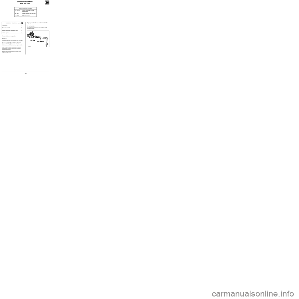
TIGHTENING TORQUES (in daN.m)Turn the wheels so the rack teeth are freed on the
valve side.
Fit tool Dir. 1306.
In this position, release the axial ball joint using
tool Dir. 1305-01.
97469R1
36-1
Page 54 of 105
STEERING ASSEMBLY
Axial ball joint
36
REFITTING
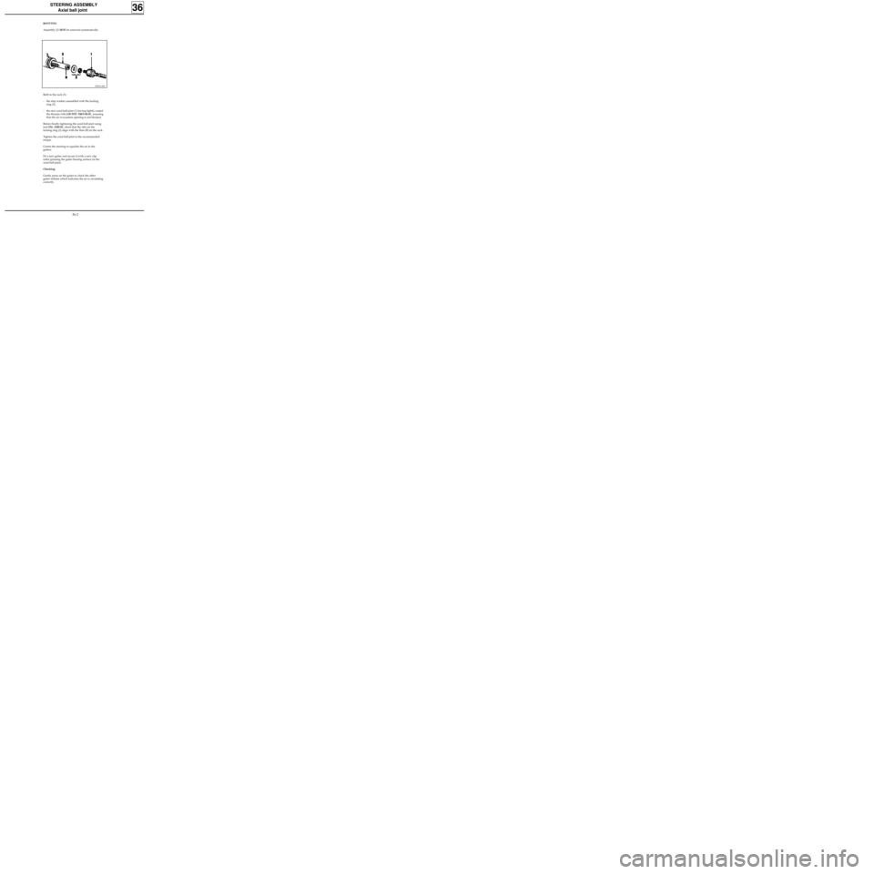
Assembly (2) MUST be renewed systematically.
83510-1R3
Refit to the rack (3) :
- the stop washer assembled with the locking
ring (2),
- the new axial ball joint (1) having lightly coated
the threads with
LOCTITE FREN-BLOC, ensuring
that the air evacuation opening is not blocked.
Before finally tightening the axial ball joint using
tool Dir. 1305-01, check that the tabs on the
locking ring (2) align with the flats (B) on the rack.
Tighten the axial ball joint to the recommended
torque.
Centre the steering to equalise the air in the
gaiters.
Fit a new gaiter and secure it with a new clip
(after greasing the gaiter bearing surface on the
axial ball joint).
Checking
Gently press on the gaiter to check the other
gaiter inflates which indicates the air is circulating
correctly.
36-2
Page 55 of 105
STEERING ASSEMBLY
Manual steering rack
36
Put the vehicle on a two post lift.
REMOVAL
Remove the front wheels.
Cut the rubber gaiter retaining clip and push the
gaiter back towards the bulkhead.
Disconnect the ball joints using tool T.Av. 476.
Remove:
- the universal joint eccentric bolt,
- the steering rack mounting bolts on the sub-
frame.
Remove the steering rack.
SPECIAL TOOLING REQUIRED
Wheel bolts 9
Track rod end nut 3.7
Steering rack mounting bolts 5.5
Universal joint eccentric bolt 2.5
T.Av. 476 Ball joint extractor
TIGHTENING TORQUES (in daN.m)REFITTING
Refitting is the reverse of removal. Observe the
recommended tightening torques.
If a new steering rack is being fitted, fit the track
rod ends in the position noted on removal.
To do this, slacken the bolt on the parallelism
adjustment sleeve and slacken the track rod end
while holding the axial ball joint using an open
wrench.
Make a mark or count the number of turns of
thread taken up so the parallelism can be pre-
adjusted on refitting.
Check the parallelism.
NOTE : the markings on the track rod ends MUST
BE OBSERVED
(one mark on right hand joint, two
marks on left hand joint).
36-3
Page 56 of 105
STEERING ASSEMBLY
Power assisted steering rack
36
SPECIAL TOOLING REQUIRED
Mot. 453-01 Hose clamp pliers
T.Av. 476 Ball joint extractor
Wheel bolts 9
Track rod end nut 3.7
Steering rack mounting bolt 5
Universal joint eccentric bolt 2.5
Engine tie bar bolt 6.5
TIGHTENING TORQUES (in daN.m)
Put the vehicle on a two post lift.
REMOVAL
Remove the front wheels.
Fit a clamp Mot. 453-01 to each of the pipes from
the oil reservoir.
NOTE :never clamp the high pressure pipes.
Cut the rubber gaiter retaining clip and push the
gaiter back towards the bulkhead.
Disconnect the ball joints using tool T.Av. 476.
Remove the universal joint eccentric bolt.
Disconnect the oxygen sensor.
Remove the exhaust downpipe.
Remove the bolt (engine side) from the engine tie
bar and pivot the engine and transmission
assembly forwards.
Insert a retaining block.
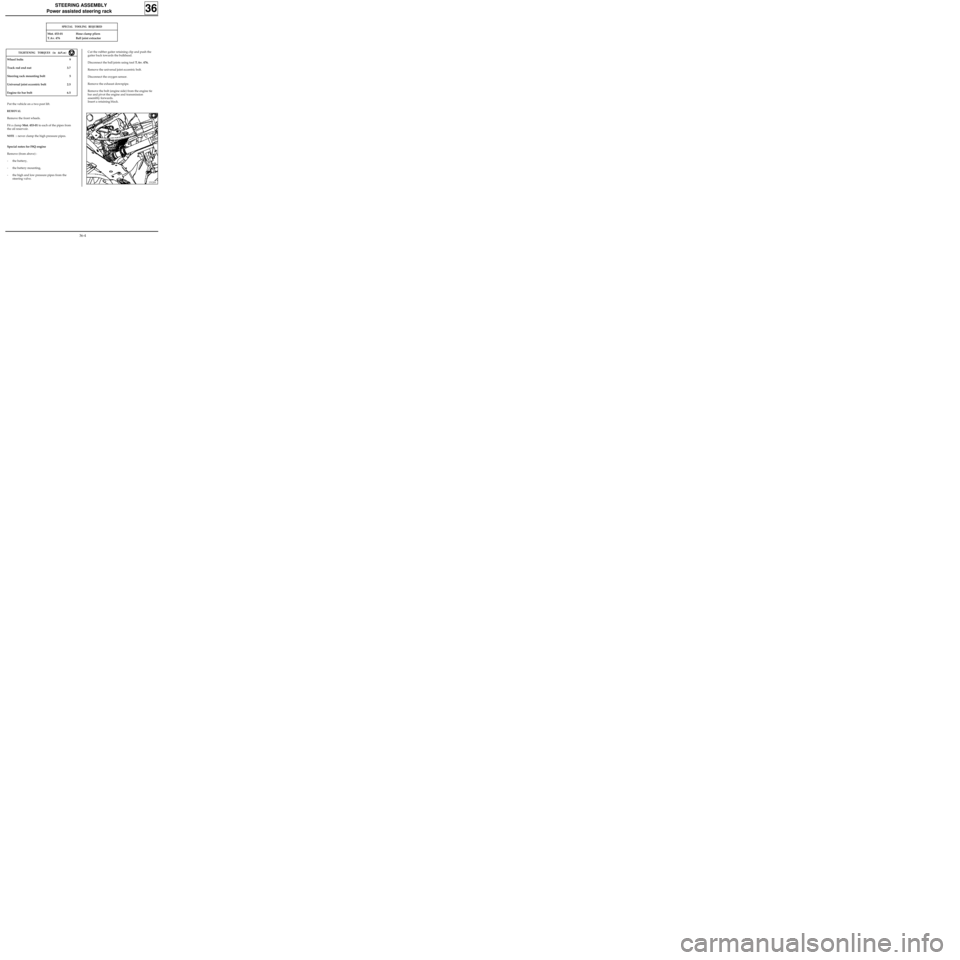
Special notes for F8Q engine
Remove (from above) :
- the battery,
- the battery mounting,
- the high and low pressure pipes from the
steering valve.
13120S
36-4
Page 57 of 105
STEERING ASSEMBLY
Power assisted steering rack
36
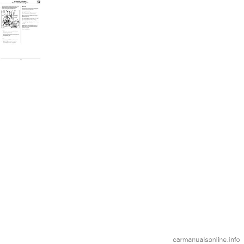
Disconnect the high and low pressure pipes on the
steering rack (take precautions to catch the oil)
and the nut on the pipe retaining bracket.
Remove:
- the two nuts on the heat shield for the right
hand steering rack bearing,
- the steering rack mounting nuts and remove it
from the timing side.
NOTE :
- do not remove the pipes between the valve
and cylinder,
- fit plugs to the steering rack openings to
prevent the introduction of impurities.
12997R
REFITTING
Refitting is the reverse of removal. Observe the
recommended tightening torques.
Fill the circuit with oil.
Turn the wheels from left to right (engine not
running) to distribute the oil in the circuit.
Repeat the operation with the engine running
then top up the level.
If a new steering rack is being fitted, fit the track
rod ends in the position noted on removal.
To do this, slacken the bolt on the parallelism
adjustment sleeve and slacken the track rod end
while holding the axial ball joint using an open
wrench.
Make a mark or count the number of turns of
thread taken up so the parallelism can be pre-
adjusted on refitting.
Check the parallelism.
36-5
Page 58 of 105
STEERING ASSEMBLY
Gaiter
36
The gaiter MUST be renewed with a new gaiter
whenever an axial ball joint is removed.
Fitting the gaiter
Use an ogive on the axial ball joint to prevent
damage to the gaiter during fitting.
Coat the gaiter bearing face on the axial ball joint
with grease to prevent the gaiter twisting.
Secure the gaiter with a new clip (supplied with
the gaiter).
NOTE : the steering MUST be at the centre point
to equalise the air.
36-6
Page 59 of 105

STEERING ASSEMBLY
Steering pushrod
36
1. Determining the source of the noise
Hold the steering rack on the pinion side and
check for transverse play (up and down).
Movement followed by a click is caused by the
pinion.
2. Adjusting for SMI steering racks
Release the adjusting nut (1) by straightening the
bent over edges (A) on the nut collar.
Check when driving that the steering returns to
the centre point.
Maximum adjustment allowed : 1 notch.
Lock the nut again in the two lugs opposite the
housing by bending over the nut collar.
ADJUSTMENT
If the steering rack pinion is noisy, before considering replacing the steering rack, check that the pinion is
correctly adjusted.
83920R
36-7