RENAULT KANGOO 1997 KC / 1.G Chassis Workshop Manual
KANGOO 1997 KC / 1.G
RENAULT
RENAULT
https://www.carmanualsonline.info/img/7/1734/w960_1734-0.png
RENAULT KANGOO 1997 KC / 1.G Chassis Workshop Manual
Trending: transmission, low oil pressure, battery, wheel bolt torque, tow, clutch, fuel
Page 1 of 105
Chassis
GENERAL
FRONT AXLE
REAR AXLE
WHEELS AND TYRES
STEERING ASSEMBLY
MECHANICAL ELEMENT CONTROLS
ELECTRONICALLY CONTROLLED SYSTEMS
Renault 1997
77 11 194 253JULY 1997Edition Anglaise
"The repair methods given by the manufacturer in this document are based on the
technical specifications current when it was prepared.
The methods may be modified as a result of changes introduced by the
manufacturer in the production of the various component units and accessories
from which his vehicles are constructed."All copyrights reserved by Renault.
Copying or translating, in part or in full, of this document or use of the service part
reference numbering system is forbidden without the prior written authority of
Renault.
C
FC0A - FC0C - FC0D - FC0E - KC0A - KC0C - KC0D - KC0E
Page 2 of 105
Page 3 of 105

Contents
Page
Chassis
GENERAL
General diagram of braking circuits
Tightening torques (in daN.m)
Dimensions of the main braking
components
Bar specifications:
- front anti-roll bar
- rear anti-roll bar
- rear suspension bars
Brake unions and pipes
Brake fluid30
30-1
30-2
30-7
30-8
30-8
30-8
30-9
30-9
31-1
31-2
31-3
31-4
31-5
31-6
31-7
31-9
31-10
31-12
ENSEMBLE MOTEUR ET BAS
Lower wishbone
Lower wishbone rubber bushes
Lower wishbone ball joint
Brake pads
Front brake calipers
Brake discs
Stub axle carrier bearing
Spring and shock absorber assembly
Anti-roll bar
Engine sub-frameFRONT AXLE31
35-1
35-4Specifications
Wheel balancing
WHEELS AND TYRES35
33-1
33-2
33-4
33-5
33-7
33-8
33-9
33-10
33-11
33-15
33-16
33-20Rear axle assembly
Brake drum
Brake cylinder
Brake linings (drum)
Bearing
Shock absorber
Anti-roll bar, tubular rear axle
Half suspension arms, tubular rear
axle
Bushes, tubular rear axle
Suspension bars, tubular rear axle
Four bar rear axle
Suspension arm bearings
REAR AXLE33
Page 4 of 105
Master cylinder
Brake servo
Air filter - Brake servo non-return
valve
Vacuum pump
Handbrake control lever
Handbrake control
Brake pipes
Braking compensator
Clutch control cable
Clutch automatic wear take-up
system
External gear control37-1
37-3
37-5
37-6
37-7
37-8
37-10
37-11
37-22
37-23
37-24
Contents
Page
MECHANICAL ELEMENT CONTROLS37
38-1
38-2
38-3
38-4
38-5
38-6
38-7
38-8
38-9
BOSCH ABS
Presentation of BOSCH ABS 5.3
Location of components
Presentation of the hydraulic
regulation assembly
Wiring diagram
Wiring diagram key
31 track connector
Diagnostic socket
Hydraulic assembly
Hydraulic braking test
ELECTRONICALLY CONTROLLED
HYDRAULIC SYSTEMS38STEERING ASSEMBLY
Axial ball joint
Manual steering rack
Power assisted steering rack
Gaiter
Steering rack pinion
Manual steering assistance pump
Steering column
36-1
36-3
36-4
36-6
36-7
36-8
36-12
36
Page 5 of 105
91563S
GENERAL
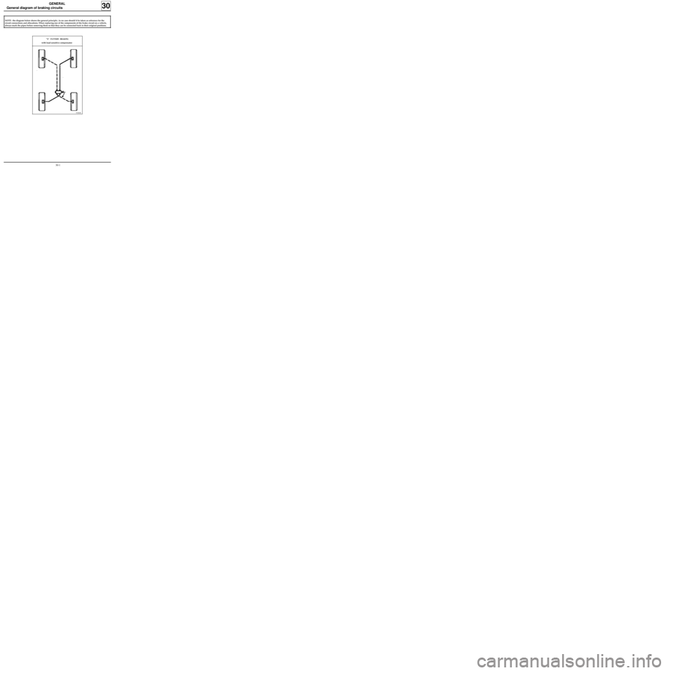
General diagram of braking circuits
30
NOTE : the diagram below shows the general principle ; in no case should it be taken as reference for the
circuit connections and allocations. When replacing one of the components of the brake circuit on a vehicle,
always mark the pipes before removing them so that they can be connected back in their original positions.
"X" PATTERN BRAKING
with load sensitive compensator
30-1
Page 6 of 105
GENERAL
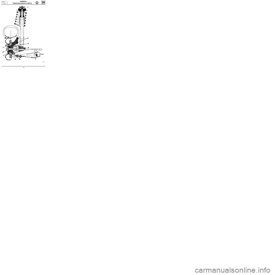
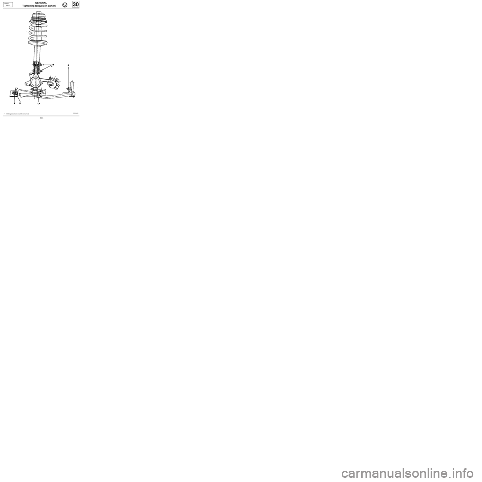
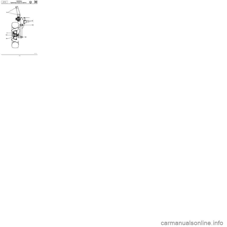
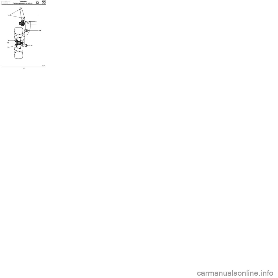
Tightening torques (in daN.m)
30
FRONT
AXLE
DI3035R
30-2
Page 7 of 105
GENERAL
Tightening torques (in daN.m)
30
FRONT
AXLE
DI3034R1*Fitting direction must be observed
30-3
Page 8 of 105
GENERAL
Tightening torques (in daN.m)
30
TUBULAR
REAR AXLE
88507-1R2
30-4
Page 9 of 105
GENERAL
Tightening torques (in daN.m)
30
4 BAR
REAR AXLE
88507-2R2
30-5
Page 10 of 105
GENERAL
Tightening torques (in daN.m)
30
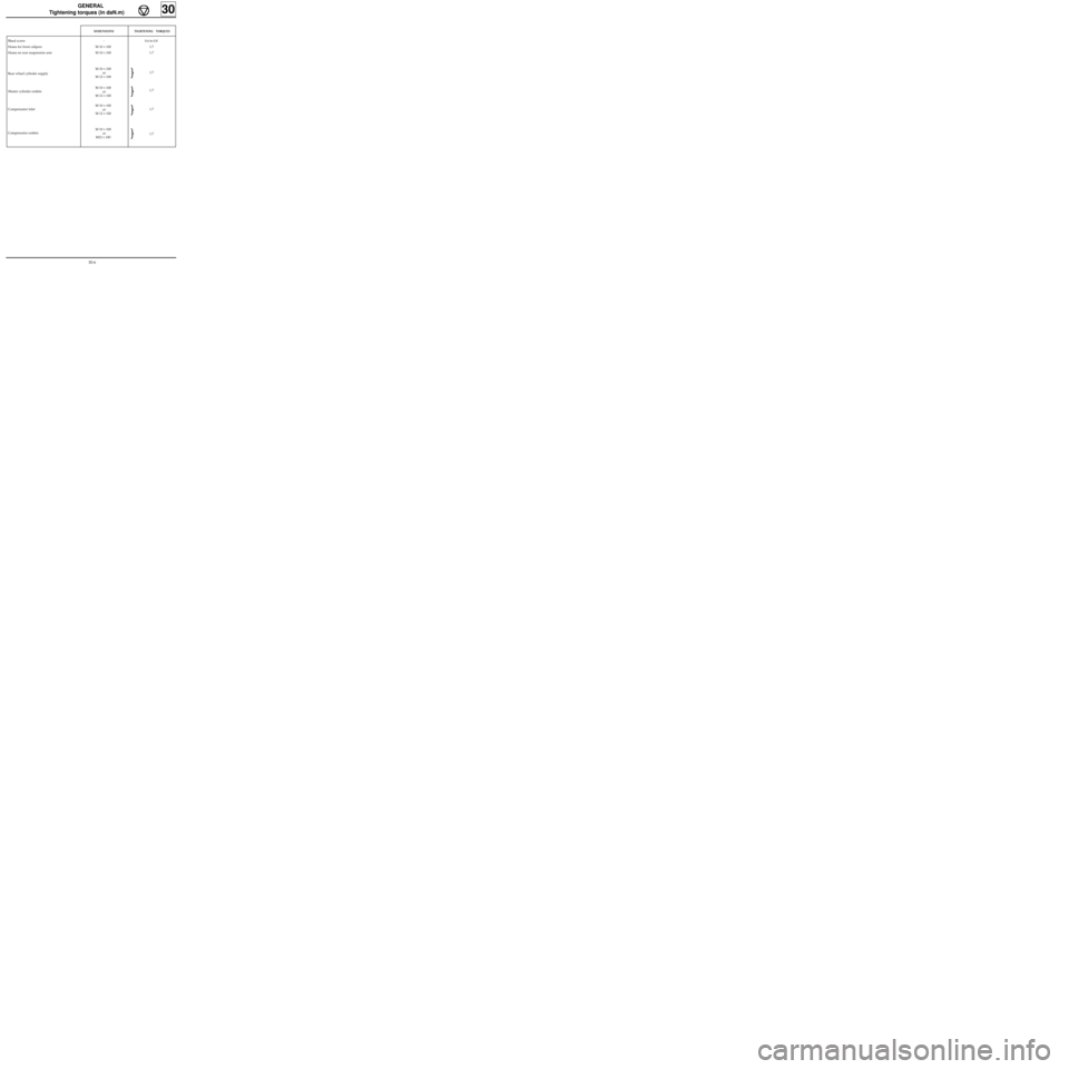
DIMENSIONSTIGHTENING TORQUES
Bleed screw
Hoses for front calipers
Hoses on rear suspension arm
Rear wheel cylinder supply
Master cylinder outlets
Compensator inlet
Compensator outlets-
M 10 × 100
M 10 × 100
M 10 × 100
or
M 12 × 100
M 10 × 100
or
M 12 × 100
M 10 × 100
or
M 12 × 100
M 10 × 100
or
M12 × 1000.6 to 0.8
1.7
1.7
1.7
1.7
1.7
1.7
30-6
Trending: length, stop start, clutch, power steering, engine oil, ignition, height adjustment
