dimensions RENAULT KANGOO 1997 KC / 1.G Engine And Peripherals Workshop Manual
[x] Cancel search | Manufacturer: RENAULT, Model Year: 1997, Model line: KANGOO, Model: RENAULT KANGOO 1997 KC / 1.GPages: 208
Page 15 of 208

ENGINE AND ENGINE PERIPHERALS
Engine and transmission assembly
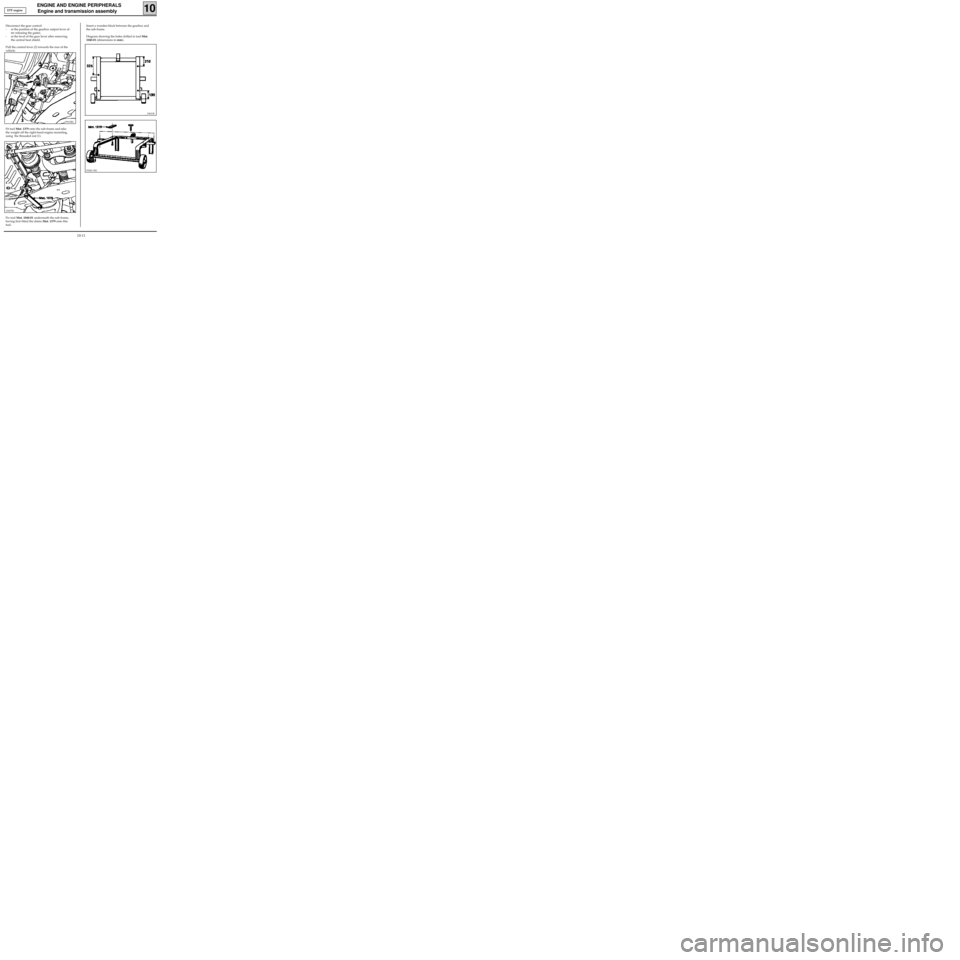
Insert a wooden block between the gearbox and
the sub-frame.
Diagram showing the holes drilled in tool Mot.
1040-01 (dimensions in mm).
10
Disconnect the gear control:
- at the position of the gearbox output lever af-
ter releasing the gaiter,
- at the level of the gear lever after removing
the central heat shield.
Pull the control lever (2) towards the rear of the
vehicle.
10621R
Fit tool Mot. 1379 onto the sub-frame and take
the weight off the right-hand engine mounting,
using the threaded rod (1).
10267R1
93912R2
Fix tool Mot. 1040-01 underneath the sub-frame,
having first fitted the shims Mot. 1379 onto this
tool.
92442-1R2
D7F engine
10-11
Page 31 of 208

ENGINE AND ENGINE PERIPHERALS
Sump
10
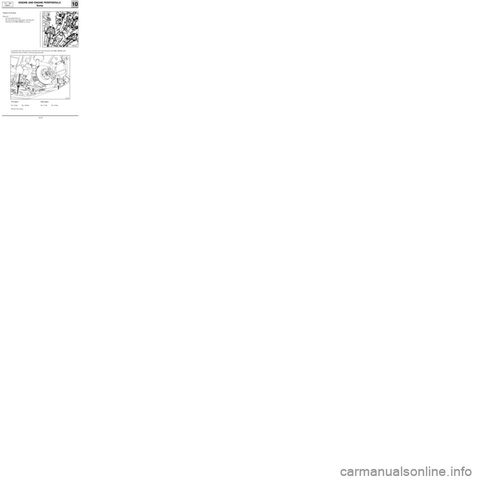
Engines of all types
Remove:
- the mounting bolts (3),
- the sub-frame mounting bolts, inserting the
threaded rods Mot. 1233-01 as you go.
12993-1R3
E7J / F8Q
engines
13507R
Gradually lower the sub-frame with the aid of the threaded rods Mot. 1233-01 until
dimensions X1 and X2 are reached approximately.
E7J engine
X
1 = 9 cm X2 = 12 cm
Remove the sump.F8Q engine
X1 = 7 cm X2 = 9 cm
10-27
Page 63 of 208

TOP AND FRONT OF ENGINE
Cylinder head gasket
11
REFITTING (special notes)
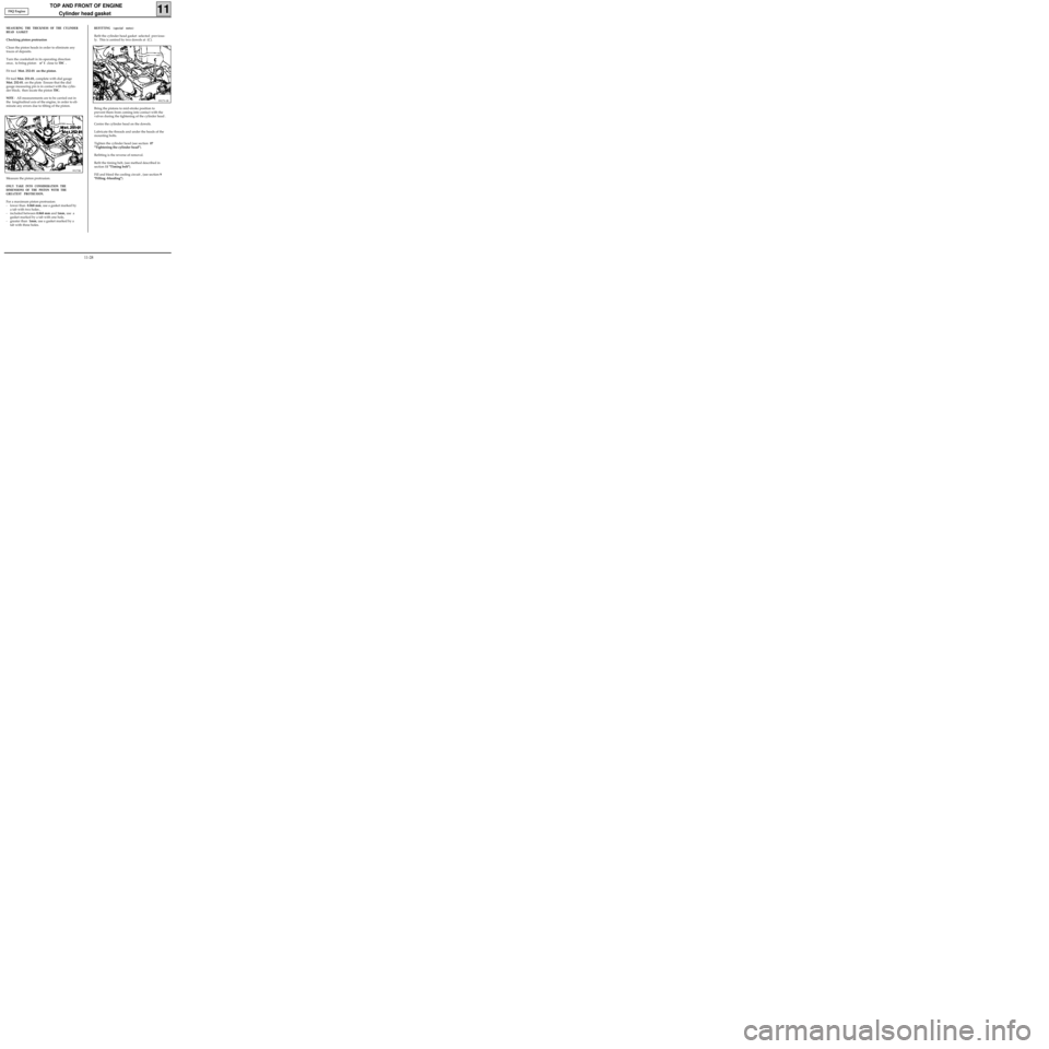
Refit the cylinder head gasket selected previous-
ly. This is centred by two dowels at (C).
99173-1R
Bring the pistons to mid-stroke position to
prevent them from coming into contact with the
valves during the tightening of the cylinder head .
Centre the cylinder head on the dowels.
Lubricate the threads and under the heads of the
mounting bolts.
Tighten the cylinder head (see section 07
"Tightening the cylinder head").
Refitting is the reverse of removal.
Refit the timing belt, (see method described in
section 11 "Timing belt").
Fill and bleed the cooling circuit , (see section 9
"Filling -bleeding").
MEASURING THE THICKNESS OF THE CYLINDER
HEAD GASKET
Checking piston protrusion
Clean the piston heads in order to eliminate any
traces of deposits.
Turn the crankshaft in its operating direction
once, to bring piston n° 1 close to
TDC .
Fit tool Mot. 252-01 on the piston.
Fit tool Mot. 251-01, complete with dial gauge
Mot. 252-01. on the plate Ensure that the dial
gauge measuring pin is in contact with the cylin-
der block; then locate the piston
TDC.
NOTE
: All measurements are to be carried out in
the longitudinal axis of the engine, in order to eli-
minate any errors due to tilting of the piston.
99173R
Measure the piston protrusion.
ONLY TAKE INTO CONSIDERATION THE
DIMENSIONS OF THE PISTON WITH THE
GREATEST PROTRUSION.
For a maximum piston protrusion:
- lower than 0.868 mm, use a gasket marked by
a tab with two holes ,
- included between 0.868 mm and 1mm, use a
gasket marked by a tab with one hole,
- greater than 1mm, use a gasket marked by a
tab with three holes. F8Q Engine
11-28
Page 64 of 208

TOP AND FRONT OF ENGINE
Replacement of valve adjusters
11
SPECIAL TOOLING REQUIRED
Mot. 1366-01 Tool for removing valve adjusters
(additional item to Mot. 1366)
TIGHTENING TORQUES (in daN.m)
Studs for mounting manifolds on
cylinder head 1
Nut for mounting manifolds on
cylinder head 2.7
Mounting bolt for strut on inlet manifold 2.5
Mounting bolt for strut on cylinder block 2.5
Place the vehicle on a two-post lift
Disconnect the battery.
CHECKING THE VALVE CLEARANCE
Remove the air filter housing along with the cy-
linder head cover.
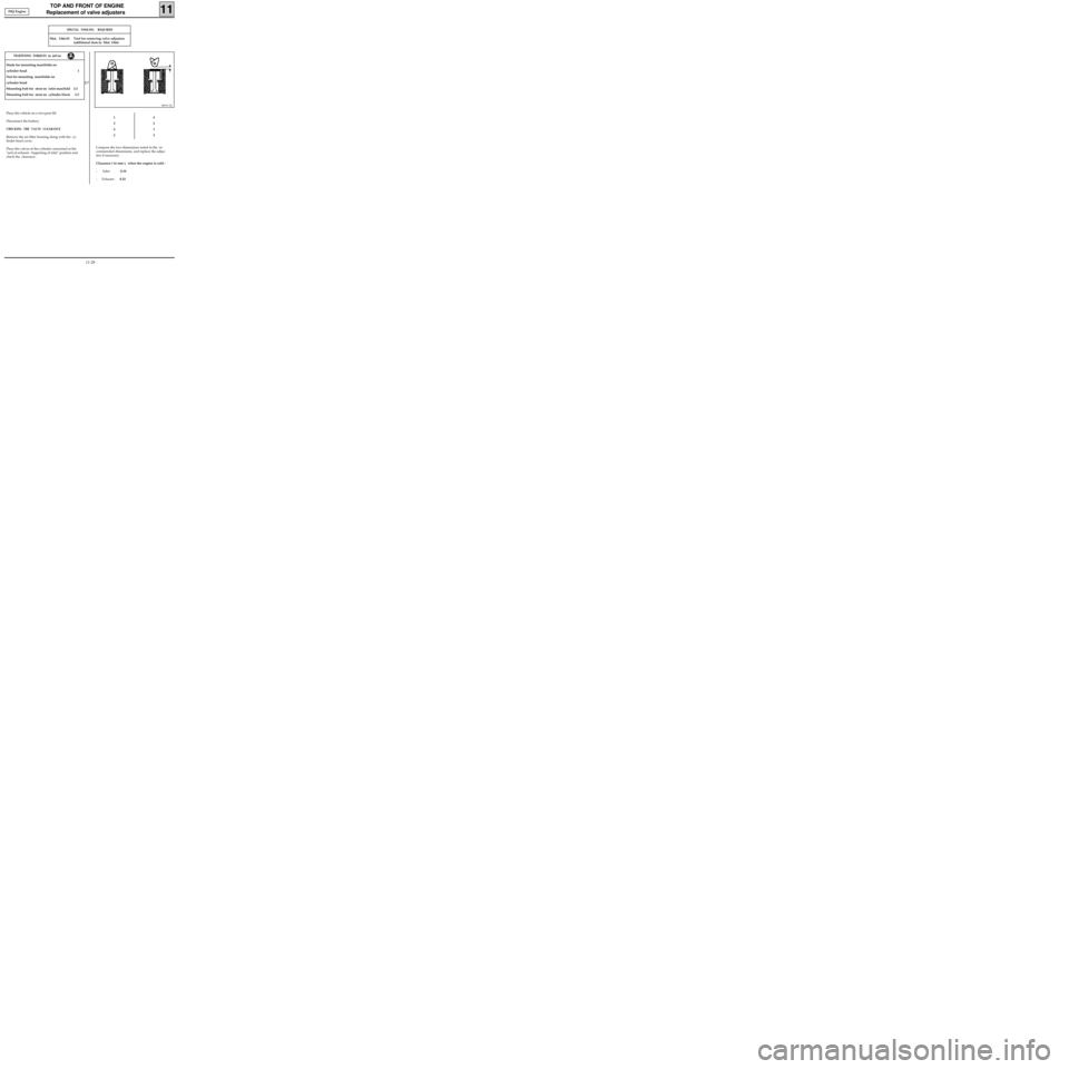
Place the valves of the cylinder concerned at the
"end of exhaust - beginning of inlet" position and
check the clearance .
86911-1S
1
3
4
24
2
1
3
Compare the two dimensions noted to the re-
commended dimensions, and replace the adjus-
ters if necessary .
Clearance ( in mm ), when the engine is cold :
- Inlet: 0.10
- Exhaust :0.25 F8Q Engine
11-29