tire pressure RENAULT KANGOO 2013 X61 / 2.G Diesel DCM 1.2 Injection Workshop Manual
[x] Cancel search | Manufacturer: RENAULT, Model Year: 2013, Model line: KANGOO, Model: RENAULT KANGOO 2013 X61 / 2.GPages: 204, PDF Size: 0.99 MB
Page 5 of 204

13B-5V1 MR-376-X76-13B000$010.mif
DIESEL INJECTION
Fault finding – Introduction13B
DCM 1.2 Injection
Program no.: 4C
Vdiag No.: 08
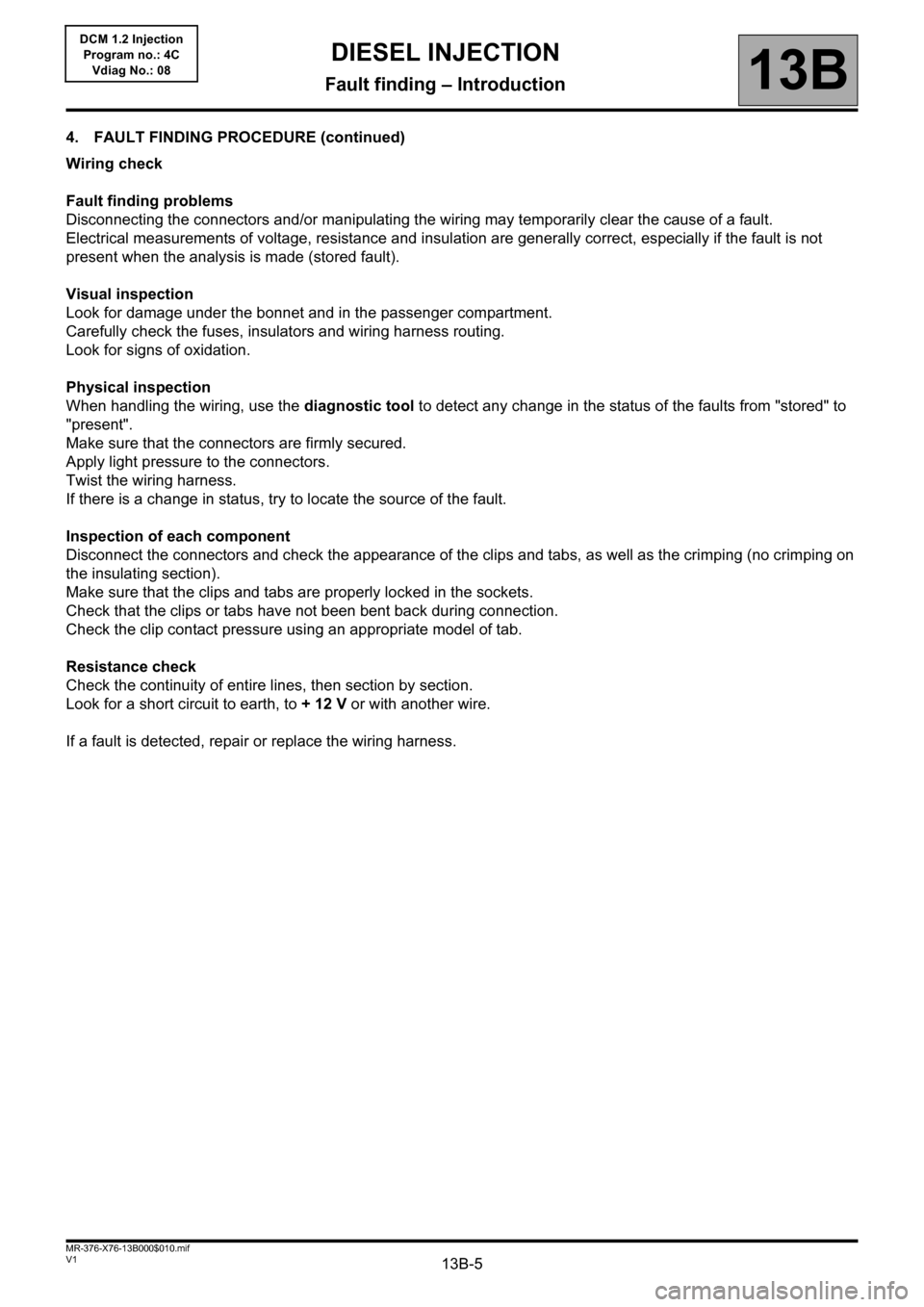
4. FAULT FINDING PROCEDURE (continued)
Wiring check
Fault finding problems
Disconnecting the connectors and/or manipulating the wiring may temporarily clear the cause of a fault.
Electrical measurements of voltage, resistance and insulation are generally correct, especially if the fault is not
present when the analysis is made (stored fault).
Visual inspection
Look for damage under the bonnet and in the passenger compartment.
Carefully check the fuses, insulators and wiring harness routing.
Look for signs of oxidation.
Physical inspection
When handling the wiring, use the diagnostic tool to detect any change in the status of the faults from "stored" to
"present".
Make sure that the connectors are firmly secured.
Apply light pressure to the connectors.
Twist the wiring harness.
If there is a change in status, try to locate the source of the fault.
Inspection of each component
Disconnect the connectors and check the appearance of the clips and tabs, as well as the crimping (no crimping on
the insulating section).
Make sure that the clips and tabs are properly locked in the sockets.
Check that the clips or tabs have not been bent back during connection.
Check the clip contact pressure using an appropriate model of tab.
Resistance check
Check the continuity of entire lines, then section by section.
Look for a short circuit to earth, to + 12 V or with another wire.
If a fault is detected, repair or replace the wiring harness.
Page 10 of 204

13B-10V1 MR-376-X76-13B000$030.mif
13B
DCM 1.2 Injection
Program no.: 4C
Vdiag No.: 08
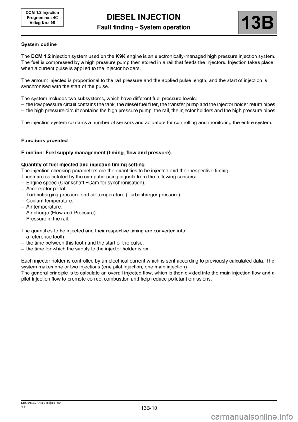
System outline
The DCM 1.2 injection system used on the K9K engine is an electronically-managed high pressure injection system.
The fuel is compressed by a high pressure pump then stored in a rail that feeds the injectors. Injection takes place
when a current pulse is applied to the injector holders.
The amount injected is proportional to the rail pressure and the applied pulse length, and the start of injection is
synchronised with the start of the pulse.
The system includes two subsystems, which have different fuel pressure levels:
– the low pressure circuit contains the tank, the diesel fuel filter, the transfer pump and the injector holder return pipes,
– the high pressure circuit contains the high pressure pump, the rail, the injector holders and the high pressure pipes.
The injection system contains a number of sensors and actuators for controlling and monitoring the entire system.
Functions provided
Function: Fuel supply management (timing, flow and pressure).
Quantity of fuel injected and injection timing setting
The injection checking parameters are the quantities to be injected and their respective timing.
These are calculated by the computer using signals from the following sensors:
– Engine speed (Crankshaft +Cam for synchronisation).
– Accelerator pedal.
– Turbocharging pressure and air temperature (Turbocharger pressure).
– Coolant temperature.
– Air temperature.
– Air charge (Flow and Pressure).
– Pressure in the rail.
The quantities to be injected and their respective timing are converted into:
– a reference tooth,
– the time between this tooth and the start of the pulse,
– the time for which the supply to the injector holder is on.
Each injector holder is controlled by an electrical current which is sent according to previously calculated data. The
system makes one or two injections (one pilot injection, one main injection).
The general principle is to calculate an overall injected flow, which is then divided into the main injection flow and a
pilot injection flow to promote correct combustion and help reduce pollutant emissions.
DIESEL INJECTION
Fault finding – System operation
Page 145 of 204

13B-145V1 MR-376-X76-13B000$130.mif
13B
DCM 1.2 Injection
Program no.: 4C
Vdiag No.: 08
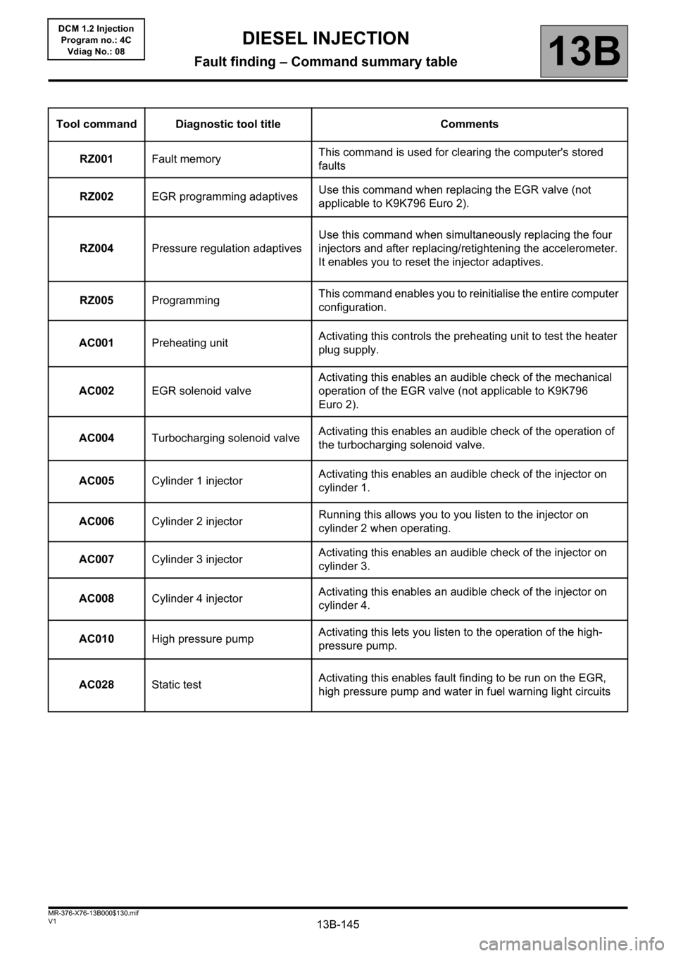
Tool command Diagnostic tool title Comments
RZ001Fault memoryThis command is used for clearing the computer's stored
faults
RZ002EGR programming adaptivesUse this command when replacing the EGR valve (not
applicable to K9K796 Euro 2).
RZ004Pressure regulation adaptivesUse this command when simultaneously replacing the four
injectors and after replacing/retightening the accelerometer.
It enables you to reset the injector adaptives.
RZ005ProgrammingThis command enables you to reinitialise the entire computer
configuration.
AC001Preheating unitActivating this controls the preheating unit to test the heater
plug supply.
AC002EGR solenoid valveActivating this enables an audible check of the mechanical
operation of the EGR valve (not applicable to K9K796
Euro 2).
AC004Turbocharging solenoid valveActivating this enables an audible check of the operation of
the turbocharging solenoid valve.
AC005Cylinder 1 injectorActivating this enables an audible check of the injector on
cylinder 1.
AC006Cylinder 2 injectorRunning this allows you to you listen to the injector on
cylinder 2 when operating.
AC007Cylinder 3 injectorActivating this enables an audible check of the injector on
cylinder 3.
AC008Cylinder 4 injectorActivating this enables an audible check of the injector on
cylinder 4.
AC010High pressure pumpActivating this lets you listen to the operation of the high-
pressure pump.
AC028Static testActivating this enables fault finding to be run on the EGR,
high pressure pump and water in fuel warning light circuits
DIESEL INJECTION
Fault finding – Command summary table