diagram RENAULT KANGOO 2013 X61 / 2.G Instrument Panel Instruments Workshop Manual
[x] Cancel search | Manufacturer: RENAULT, Model Year: 2013, Model line: KANGOO, Model: RENAULT KANGOO 2013 X61 / 2.GPages: 59, PDF Size: 0.28 MB
Page 2 of 59
83A-2
AFTER REPAIRCheck for correct operation.
V1 MR-376-X76-83A000$010.mif
83A
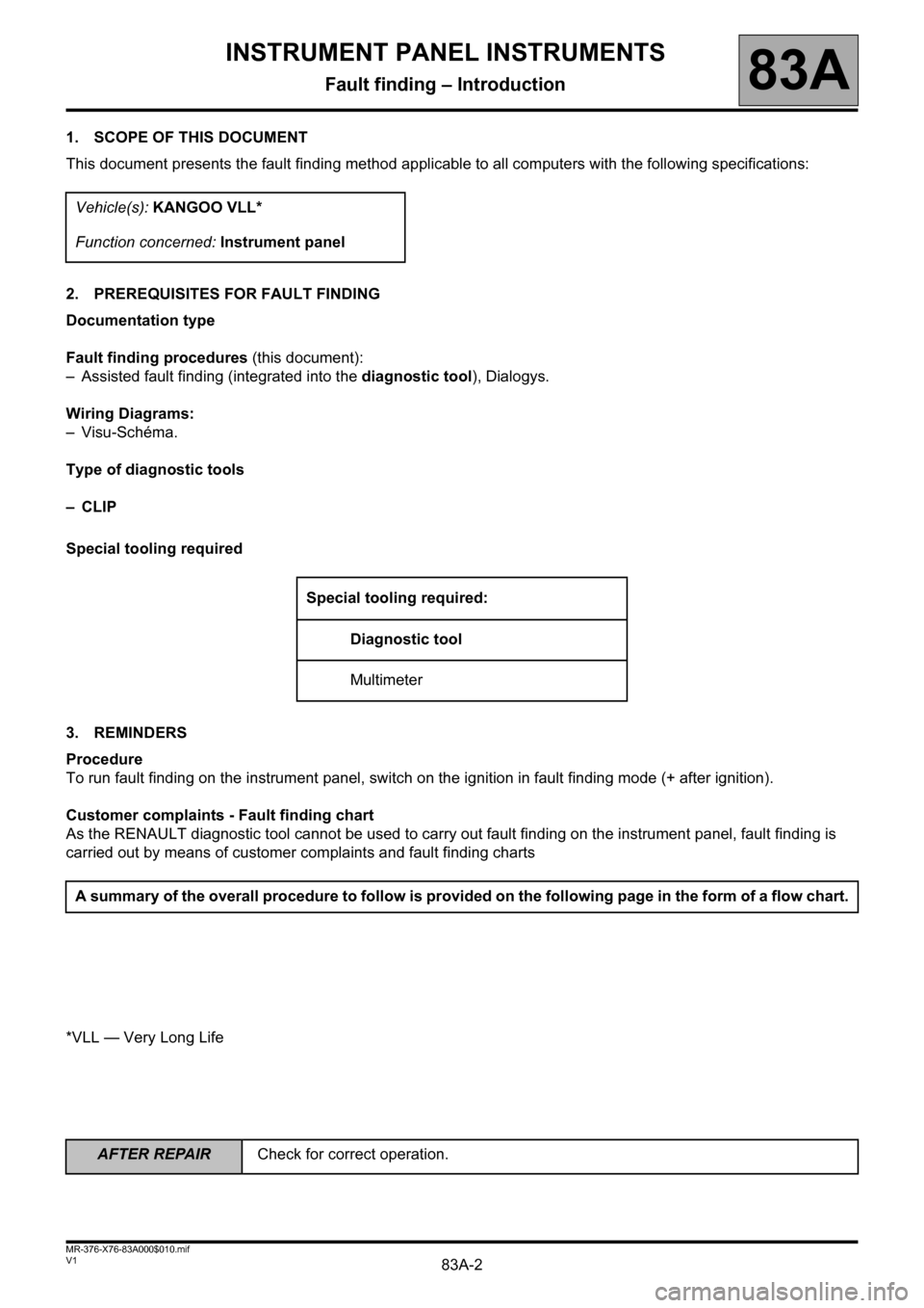
1. SCOPE OF THIS DOCUMENT
This document presents the fault finding method applicable to all computers with the following specifications:
2. PREREQUISITES FOR FAULT FINDING
Documentation type
Fault finding procedures (this document):
– Assisted fault finding (integrated into the diagnostic tool), Dialogys.
Wiring Diagrams:
– Visu-Schéma.
Type of diagnostic tools
–CLIP
Special tooling required
3. REMINDERS
Procedure
To run fault finding on the instrument panel, switch on the ignition in fault finding mode (+ after ignition).
Customer complaints - Fault finding chart
As the RENAULT diagnostic tool cannot be used to carry out fault finding on the instrument panel, fault finding is
carried out by means of customer complaints and fault finding charts
*VLL — Very Long LifeVehicle(s): KANGOO VLL*
Function concerned: Instrument panel
Special tooling required:
Diagnostic tool
Multimeter
A summary of the overall procedure to follow is provided on the following page in the form of a flow chart.
INSTRUMENT PANEL INSTRUMENTS
Fault finding – Introduction
Page 20 of 59
83A-20
AFTER REPAIRCheck for correct operation.
V1 MR-376-X76-83A000$060.mif
83A
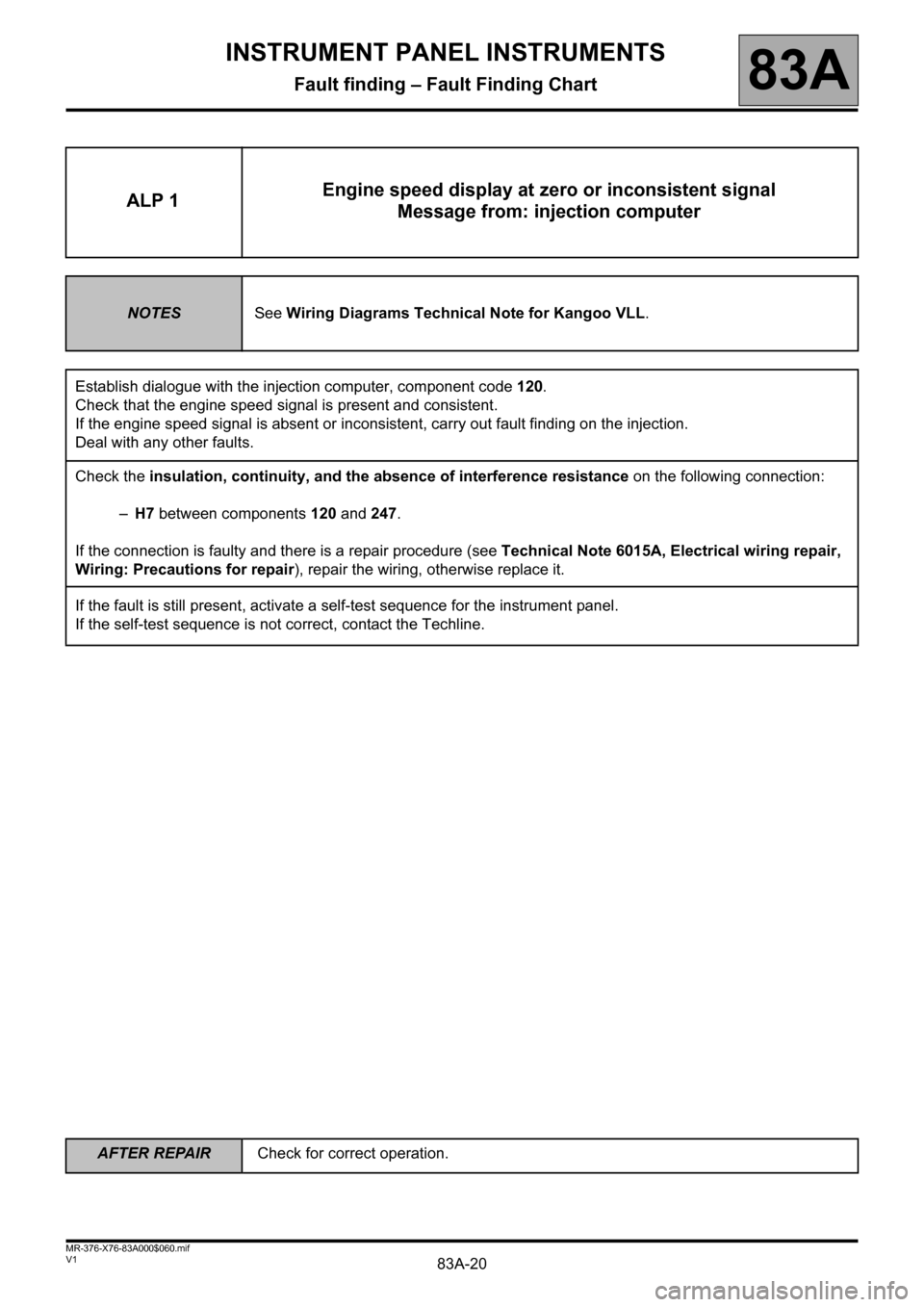
ALP 1Engine speed display at zero or inconsistent signal
Message from: injection computer
NOTESSee Wiring Diagrams Technical Note for Kangoo VLL.
Establish dialogue with the injection computer, component code 120.
Check that the engine speed signal is present and consistent.
If the engine speed signal is absent or inconsistent, carry out fault finding on the injection.
Deal with any other faults.
Check the insulation, continuity, and the absence of interference resistance on the following connection:
–H7 between components 120 and 247.
If the connection is faulty and there is a repair procedure (see Technical Note 6015A, Electrical wiring repair,
Wiring: Precautions for repair), repair the wiring, otherwise replace it.
If the fault is still present, activate a self-test sequence for the instrument panel.
If the self-test sequence is not correct, contact the Techline.
INSTRUMENT PANEL INSTRUMENTS
Fault finding – Fault Finding Chart
Page 21 of 59
83A-21
AFTER REPAIRCheck for correct operation.
V1 MR-376-X76-83A000$060.mif
INSTRUMENT PANEL INSTRUMENTS
Fault finding – Fault Finding Chart83A
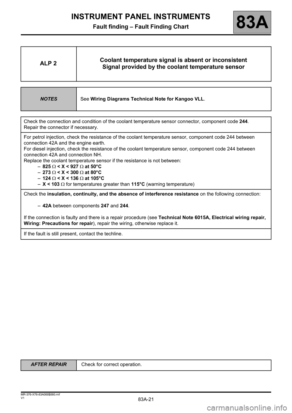
ALP 2Coolant temperature signal is absent or inconsistent
Signal provided by the coolant temperature sensor
NOTESSee Wiring Diagrams Technical Note for Kangoo VLL.
Check the connection and condition of the coolant temperature sensor connector, component code 244.
Repair the connector if necessary.
For petrol injection, check the resistance of the coolant temperature sensor, component code 244 between
connection 42A and the engine earth.
For diesel injection, check the resistance of the coolant temperature sensor, component code 244 between
connection 42A and connection NH.
Replace the coolant temperature sensor if the resistance is not between:
–825 < X < 927 at 50°C
–273 < X < 300 at 80°C
–124 < X < 136 at 105°C
–X < 103 for temperatures greater than 115°C (warning temperature)
Check the insulation, continuity, and the absence of interference resistance on the following connection:
–42A between components247 and 244.
If the connection is faulty and there is a repair procedure (see Technical Note 6015A, Electrical wiring repair,
Wiring: Precautions for repair), repair the wiring, otherwise replace it.
If the fault is still present, contact the techline.
Page 22 of 59
83A-22
AFTER REPAIRCheck for correct operation.
V1 MR-376-X76-83A000$060.mif
INSTRUMENT PANEL INSTRUMENTS
Fault finding – Fault Finding Chart83A
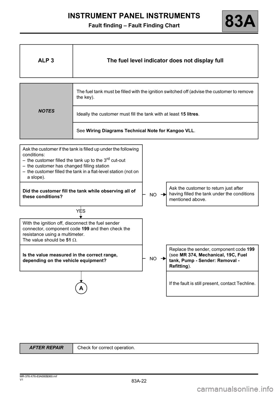
ALP 3 The fuel level indicator does not display full
NOTESThe fuel tank must be filled with the ignition switched off (advise the customer to remove
the key).
Ideally the customer must fill the tank with at least 15 litres.
See Wiring Diagrams Technical Note for Kangoo VLL.
Ask the customer if the tank is filled up under the following
conditions:
– the customer filled the tank up to the 3
rd cut-out
– the customer has changed filling station
– the customer filled the tank in a flat-level station (not on
a slope).
Did the customer fill the tank while observing all of
these conditions?Ask the customer to return just after
having filled the tank under the conditions
mentioned above.
With the ignition off, disconnect the fuel sender
connector, component code 199 and then check the
resistance using a multimeter.
The value should be 51 .
Is the value measured in the correct range,
depending on the vehicle equipment?Replace the sender, component code 199
(see MR 374, Mechanical, 19C, Fuel
tank, Pump - Sender: Removal -
Refitting).
If the fault is still present, contact Techline.
NO
YES
NO
A
Page 27 of 59
83A-27
AFTER REPAIRCheck for correct operation.
V1 MR-376-X76-83A000$060.mif
INSTRUMENT PANEL INSTRUMENTS
Fault finding – Fault Finding Chart83A
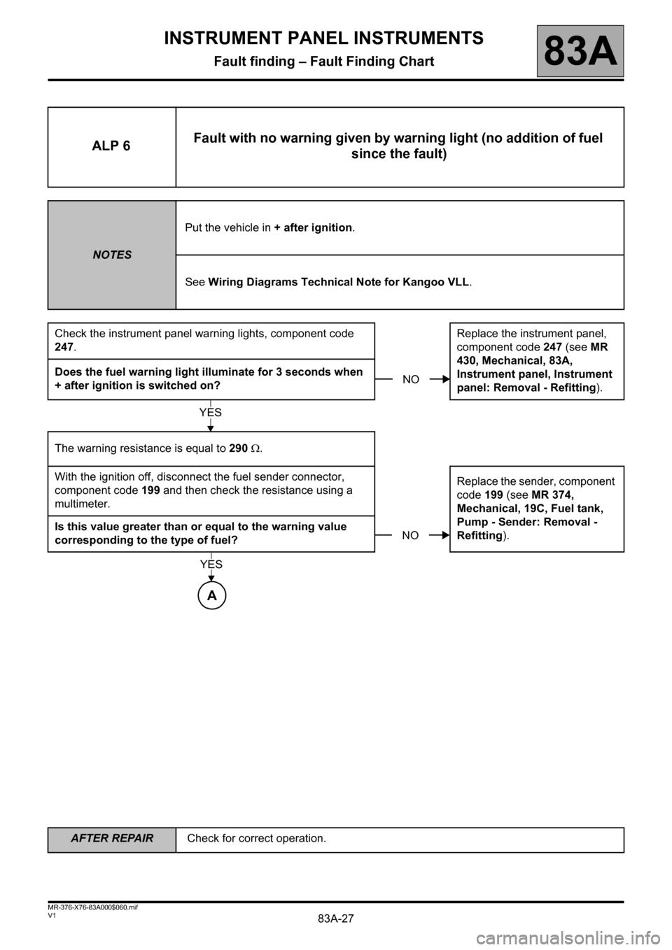
ALP 6Fault with no warning given by warning light (no addition of fuel
since the fault)
NOTESPut the vehicle in + after ignition.
See Wiring Diagrams Technical Note for Kangoo VLL.
Check the instrument panel warning lights, component code
247.Replace the instrument panel,
component code 247 (see MR
430, Mechanical, 83A,
Instrument panel, Instrument
panel: Removal - Refitting). Does the fuel warning light illuminate for 3 seconds when
+ after ignition is switched on?
The warning resistance is equal to 290 .
With the ignition off, disconnect the fuel sender connector,
component code 199 and then check the resistance using a
multimeter.Replace the sender, component
code 199 (see MR 374,
Mechanical, 19C, Fuel tank,
Pump - Sender: Removal -
Refitting). Is this value greater than or equal to the warning value
corresponding to the type of fuel?
NO
YES
NO
A
YES
Page 29 of 59
83A-29
AFTER REPAIRCheck for correct operation.
V1 MR-376-X76-83A000$060.mif
INSTRUMENT PANEL INSTRUMENTS
Fault finding – Fault Finding Chart83A
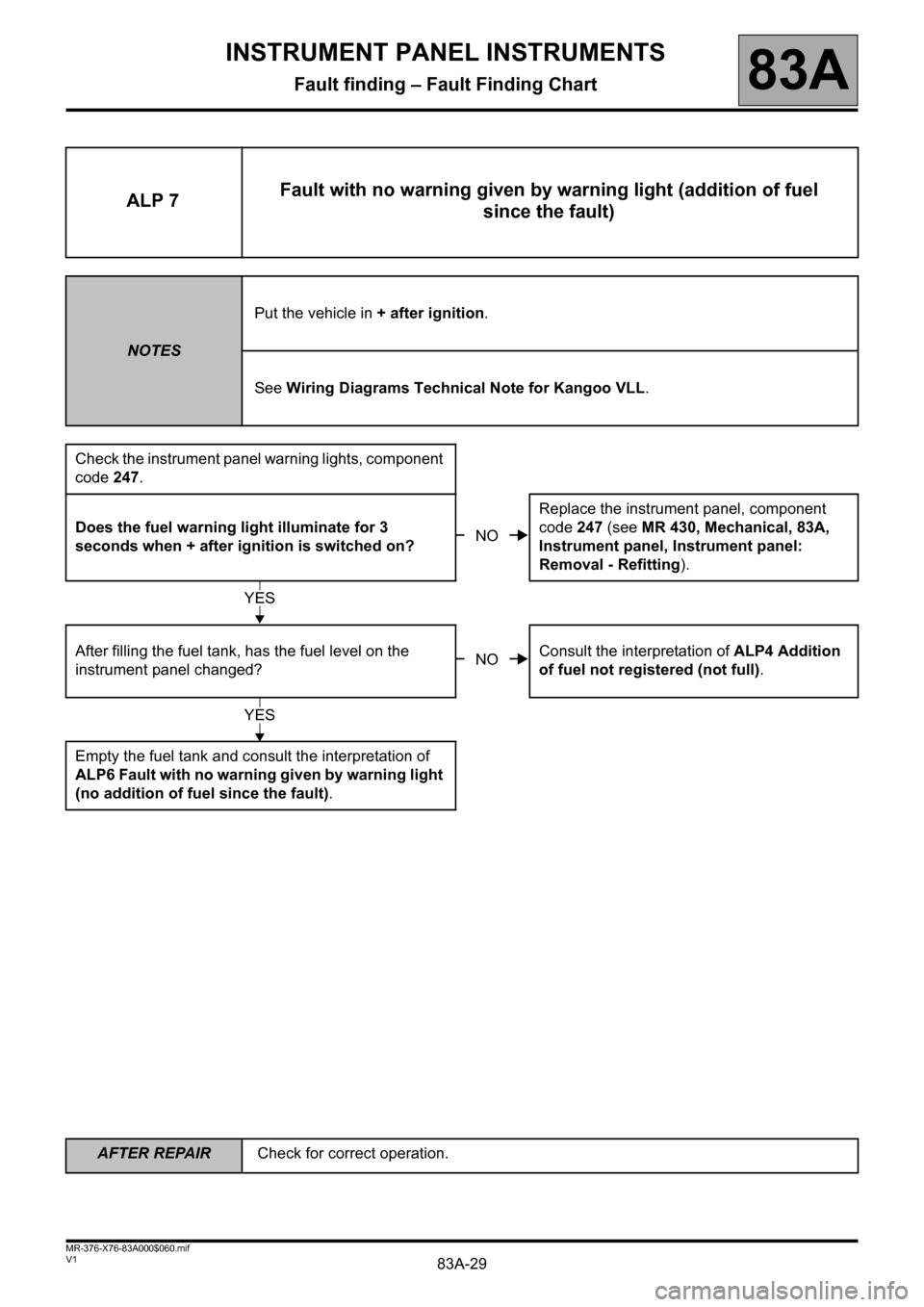
ALP 7Fault with no warning given by warning light (addition of fuel
since the fault)
NOTESPut the vehicle in + after ignition.
See Wiring Diagrams Technical Note for Kangoo VLL.
Check the instrument panel warning lights, component
code 247.
Does the fuel warning light illuminate for 3
seconds when + after ignition is switched on?Replace the instrument panel, component
code 247 (see MR 430, Mechanical, 83A,
Instrument panel, Instrument panel:
Removal - Refitting).
After filling the fuel tank, has the fuel level on the
instrument panel changed?Consult the interpretation of ALP4 Addition
of fuel not registered (not full).
Empty the fuel tank and consult the interpretation of
ALP6 Fault with no warning given by warning light
(no addition of fuel since the fault).
NO
YES
NO
YES
Page 31 of 59
83A-31
AFTER REPAIRCheck for correct operation.
V1 MR-376-X76-83A000$060.mif
INSTRUMENT PANEL INSTRUMENTS
Fault finding – Fault Finding Chart83A
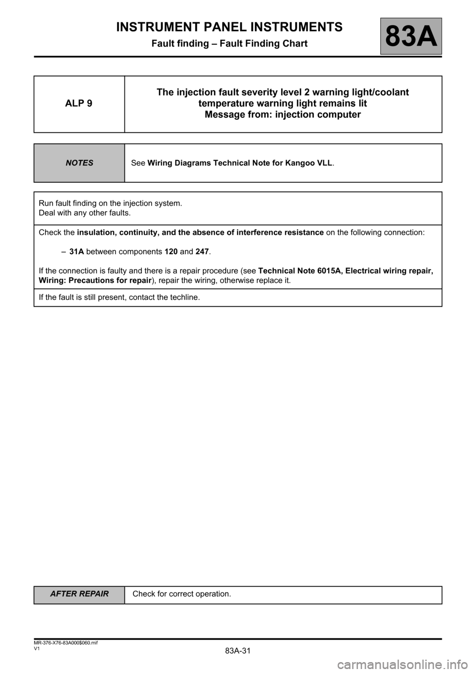
ALP 9The injection fault severity level 2 warning light/coolant
temperature warning light remains lit
Message from: injection computer
NOTESSee Wiring Diagrams Technical Note for Kangoo VLL.
Run fault finding on the injection system.
Deal with any other faults.
Check the insulation, continuity, and the absence of interference resistance on the following connection:
–31A between components120 and 247.
If the connection is faulty and there is a repair procedure (see Technical Note 6015A, Electrical wiring repair,
Wiring: Precautions for repair), repair the wiring, otherwise replace it.
If the fault is still present, contact the techline.
Page 32 of 59
83A-32
AFTER REPAIRCheck for correct operation.
V1 MR-376-X76-83A000$060.mif
INSTRUMENT PANEL INSTRUMENTS
Fault finding – Fault Finding Chart83A
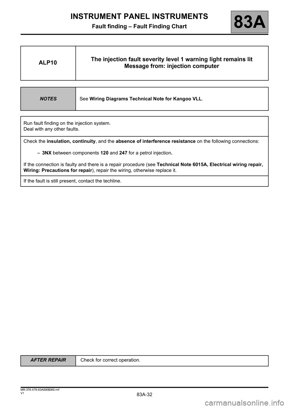
ALP10The injection fault severity level 1 warning light remains lit
Message from: injection computer
NOTESSee Wiring Diagrams Technical Note for Kangoo VLL.
Run fault finding on the injection system.
Deal with any other faults.
Check the insulation, continuity, and the absence of interference resistance on the following connections:
–3NX between components 120 and 247 for a petrol injection.
If the connection is faulty and there is a repair procedure (see Technical Note 6015A, Electrical wiring repair,
Wiring: Precautions for repair), repair the wiring, otherwise replace it.
If the fault is still present, contact the techline.
Page 33 of 59
83A-33
AFTER REPAIRCheck for correct operation.
V1 MR-376-X76-83A000$060.mif
INSTRUMENT PANEL INSTRUMENTS
Fault finding – Fault Finding Chart83A
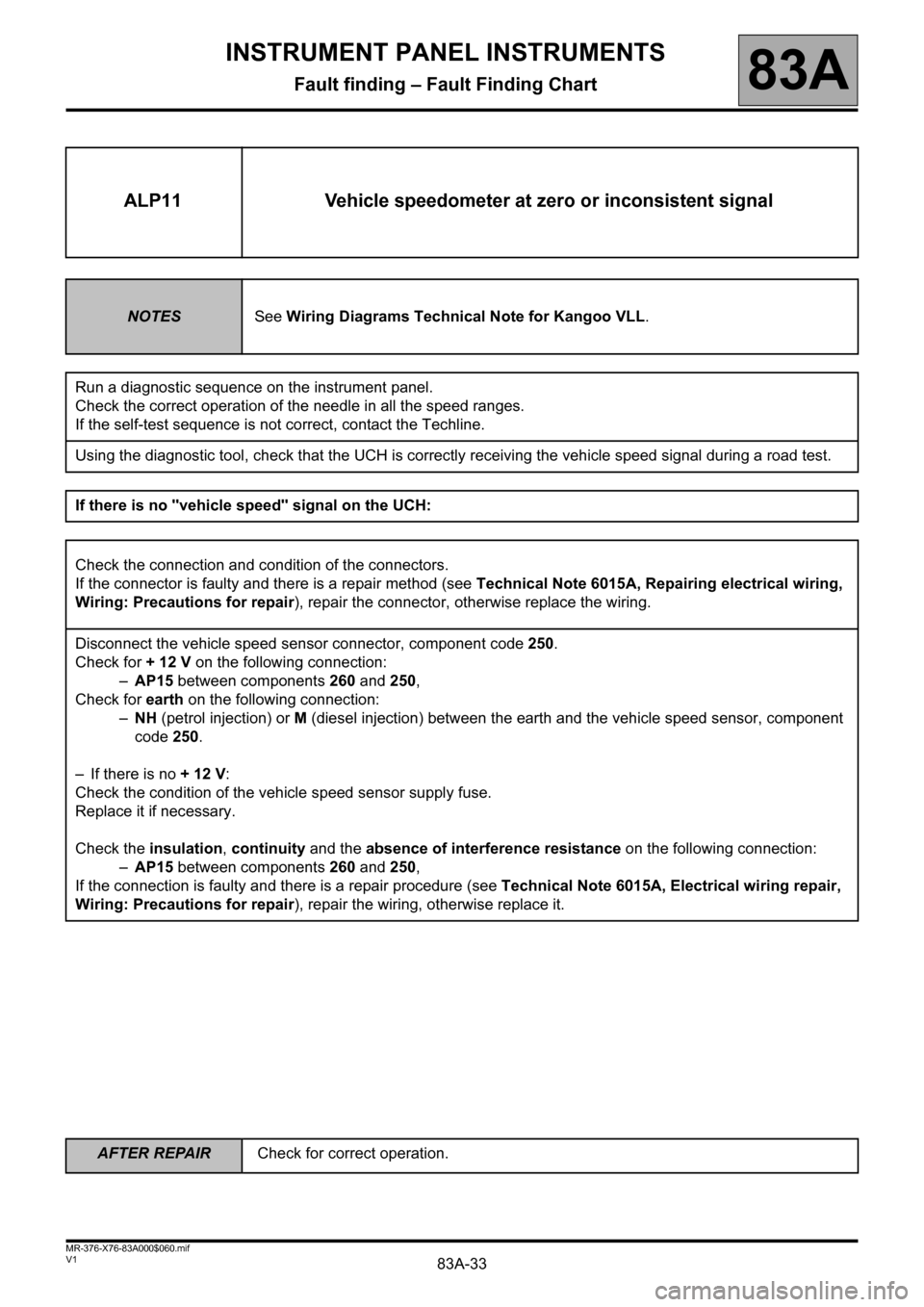
ALP11 Vehicle speedometer at zero or inconsistent signal
NOTESSee Wiring Diagrams Technical Note for Kangoo VLL.
Run a diagnostic sequence on the instrument panel.
Check the correct operation of the needle in all the speed ranges.
If the self-test sequence is not correct, contact the Techline.
Using the diagnostic tool, check that the UCH is correctly receiving the vehicle speed signal during a road test.
If there is no "vehicle speed" signal on the UCH:
Check the connection and condition of the connectors.
If the connector is faulty and there is a repair method (see Technical Note 6015A, Repairing electrical wiring,
Wiring: Precautions for repair), repair the connector, otherwise replace the wiring.
Disconnect the vehicle speed sensor connector, component code 250.
Check for + 12 V on the following connection:
–AP15 between components 260 and 250,
Check for earth on the following connection:
–NH (petrol injection) or M (diesel injection) between the earth and the vehicle speed sensor, component
code 250.
– If there is no + 12 V:
Check the condition of the vehicle speed sensor supply fuse.
Replace it if necessary.
Check the insulation, continuity and the absence of interference resistance on the following connection:
–AP15 between components 260 and 250,
If the connection is faulty and there is a repair procedure (see Technical Note 6015A, Electrical wiring repair,
Wiring: Precautions for repair), repair the wiring, otherwise replace it.
Page 38 of 59
83A-38
AFTER REPAIRCheck for correct operation.
V1 MR-376-X76-83A000$060.mif
INSTRUMENT PANEL INSTRUMENTS
Fault finding – Fault Finding Chart83A
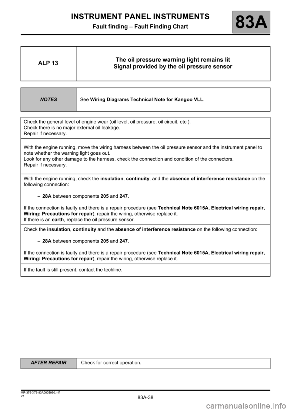
ALP 13The oil pressure warning light remains lit
Signal provided by the oil pressure sensor
NOTESSee Wiring Diagrams Technical Note for Kangoo VLL.
Check the general level of engine wear (oil level, oil pressure, oil circuit, etc.).
Check there is no major external oil leakage.
Repair if necessary.
With the engine running, move the wiring harness between the oil pressure sensor and the instrument panel to
note whether the warning light goes out.
Look for any other damage to the harness, check the connection and condition of the connectors.
Repair if necessary.
With the engine running, check the insulation, continuity, and the absence of interference resistance on the
following connection:
–28A between components 205 and 247.
If the connection is faulty and there is a repair procedure (see Technical Note 6015A, Electrical wiring repair,
Wiring: Precautions for repair), repair the wiring, otherwise replace it.
If there is an earth, replace the oil pressure sensor.
Check the insulation, continuity and the absence of interference resistance on the following connection:
–28A between components 205 and 247.
If the connection is faulty and there is a repair procedure (see Technical Note 6015A, Electrical wiring repair,
Wiring: Precautions for repair), repair the wiring, otherwise replace it.
If the fault is still present, contact the techline.