handbrake RENAULT KANGOO 2013 X61 / 2.G Instrument Panel Instruments Workshop Manual
[x] Cancel search | Manufacturer: RENAULT, Model Year: 2013, Model line: KANGOO, Model: RENAULT KANGOO 2013 X61 / 2.GPages: 59, PDF Size: 0.28 MB
Page 10 of 59
83A-10
AFTER REPAIRCheck for correct operation.
V1 MR-376-X76-83A000$020.mif
INSTRUMENT PANEL INSTRUMENTS
Fault finding – System operation83A
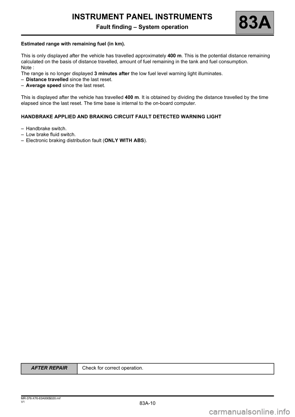
Estimated range with remaining fuel (in km).
This is only displayed after the vehicle has travelled approximately 400 m. This is the potential distance remaining
calculated on the basis of distance travelled, amount of fuel remaining in the tank and fuel consumption.
Note :
The range is no longer displayed 3 minutes after the low fuel level warning light illuminates.
–Distance travelled since the last reset.
–Average speed since the last reset.
This is displayed after the vehicle has travelled 400 m. It is obtained by dividing the distance travelled by the time
elapsed since the last reset. The time base is internal to the on-board computer.
HANDBRAKE APPLIED AND BRAKING CIRCUIT FAULT DETECTED WARNING LIGHT
– Handbrake switch.
– Low brake fluid switch.
– Electronic braking distribution fault (ONLY WITH ABS).
Page 12 of 59
83A-12
AFTER REPAIRCheck for correct operation.
V1 MR-376-X76-83A000$020.mif
INSTRUMENT PANEL INSTRUMENTS
Fault finding – System operation83A
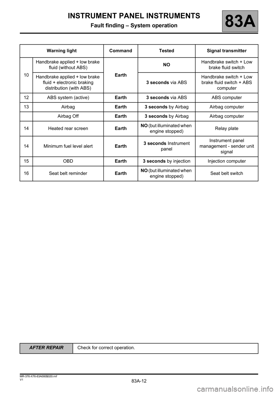
Warning light Command Tested Signal transmitter
10Handbrake applied + low brake
fluid (without ABS)
EarthNOHandbrake switch + Low
brake fluid switch
Handbrake applied + low brake
fluid + electronic braking
distribution (with ABS)3 seconds via ABSHandbrake switch + Low
brake fluid switch + ABS
computer
12 ABS system (active)Earth 3 seconds via ABS ABS computer
13 AirbagEarth 3 seconds by Airbag Airbag computer
Airbag OffEarth 3 seconds by Airbag Airbag computer
14 Heated rear screenEarthNO (but illuminated when
engine stopped)Relay plate
14 Minimum fuel level alertEarth3 seconds Instrument
panelInstrument panel
management - sender unit
signal
15 OBDEarth 3 seconds by injection Injection computer
16 Seat belt reminderEarthNO (but illuminated when
engine stopped)Seat belt switch
Page 14 of 59
83A-14
AFTER REPAIRCheck for correct operation.
V1 MR-376-X76-83A000$030.mif
INSTRUMENT PANEL INSTRUMENTS
Fault finding – Allocation of computer tracks83A
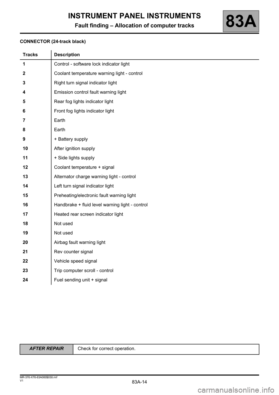
CONNECTOR (24-track black)
Tracks Description
1Control - software lock indicator light
2Coolant temperature warning light - control
3Right turn signal indicator light
4Emission control fault warning light
5Rear fog lights indicator light
6Front fog lights indicator light
7 Earth
8Earth
9+ Battery supply
10After ignition supply
11+ Side lights supply
12Coolant temperature + signal
13Alternator charge warning light - control
14Left turn signal indicator light
15Preheating/electronic fault warning light
16Handbrake + fluid level warning light - control
17Heated rear screen indicator light
18Not used
19Not used
20Airbag fault warning light
21Rev counter signal
22Vehicle speed signal
23Trip computer scroll - control
24Fuel sending unit + signal
Page 18 of 59
83A-18
AFTER REPAIRCheck for correct operation.
V1 MR-376-X76-83A000$050.mif
INSTRUMENT PANEL INSTRUMENTS
Fault finding – Customer complaints83A
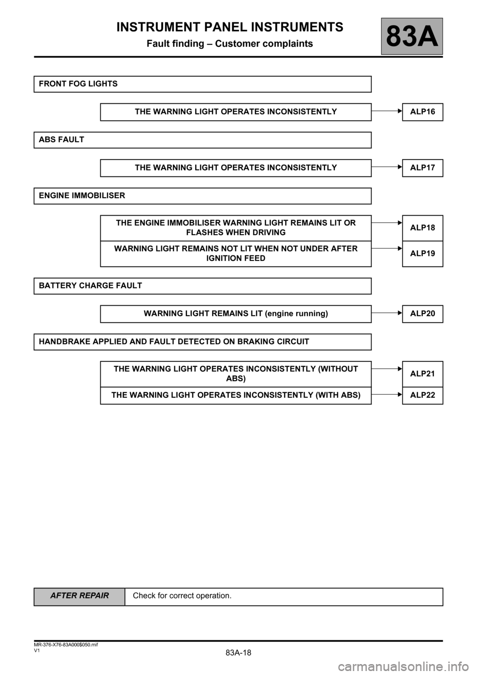
FRONT FOG LIGHTS
THE WARNING LIGHT OPERATES INCONSISTENTLY ALP16
ABS FAULT
THE WARNING LIGHT OPERATES INCONSISTENTLY ALP17
ENGINE IMMOBILISER
THE ENGINE IMMOBILISER WARNING LIGHT REMAINS LIT OR
FLASHES WHEN DRIVINGALP18
WARNING LIGHT REMAINS NOT LIT WHEN NOT UNDER AFTER
IGNITION FEEDALP19
BATTERY CHARGE FAULT
WARNING LIGHT REMAINS LIT (engine running) ALP20
HANDBRAKE APPLIED AND FAULT DETECTED ON BRAKING CIRCUIT
THE WARNING LIGHT OPERATES INCONSISTENTLY (WITHOUT
ABS)ALP21
THE WARNING LIGHT OPERATES INCONSISTENTLY (WITH ABS) ALP22
Page 50 of 59
83A-50
AFTER REPAIRCheck for correct operation.
V1 MR-376-X76-83A000$070.mif
INSTRUMENT PANEL INSTRUMENTS
Fault finding – Fault Finding Chart83A
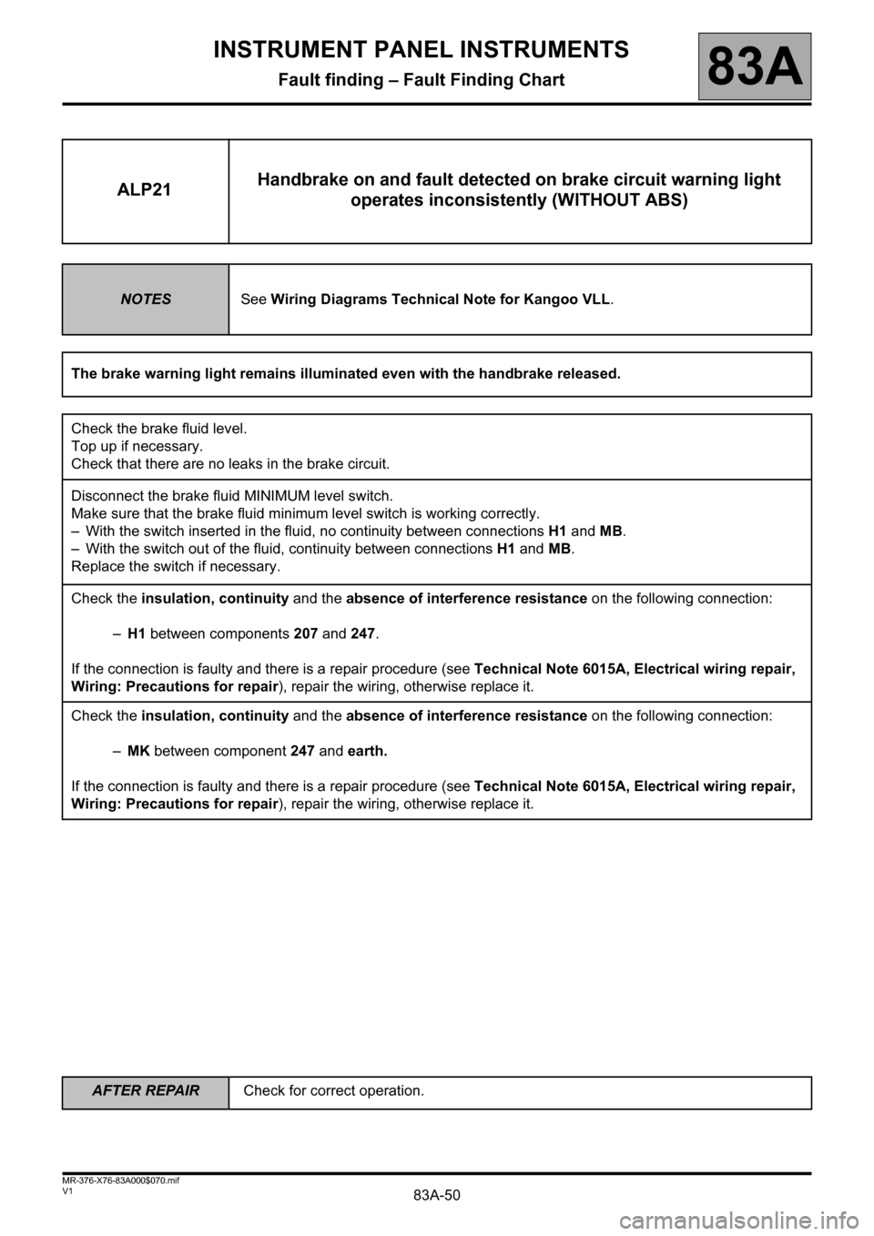
ALP21Handbrake on and fault detected on brake circuit warning light
operates inconsistently (WITHOUT ABS)
NOTESSee Wiring Diagrams Technical Note for Kangoo VLL.
The brake warning light remains illuminated even with the handbrake released.
Check the brake fluid level.
Top up if necessary.
Check that there are no leaks in the brake circuit.
Disconnect the brake fluid MINIMUM level switch.
Make sure that the brake fluid minimum level switch is working correctly.
– With the switch inserted in the fluid, no continuity between connections H1 and MB.
– With the switch out of the fluid, continuity between connections H1 and MB.
Replace the switch if necessary.
Check the insulation, continuity and the absence of interference resistance on the following connection:
–H1 between components 207 and 247.
If the connection is faulty and there is a repair procedure (see Technical Note 6015A, Electrical wiring repair,
Wiring: Precautions for repair), repair the wiring, otherwise replace it.
Check the insulation, continuity and the absence of interference resistance on the following connection:
–MK between component 247 and earth.
If the connection is faulty and there is a repair procedure (see Technical Note 6015A, Electrical wiring repair,
Wiring: Precautions for repair), repair the wiring, otherwise replace it.
Page 51 of 59
83A-51
AFTER REPAIRCheck for correct operation.
V1 MR-376-X76-83A000$070.mif
INSTRUMENT PANEL INSTRUMENTS
Fault finding – Fault Finding Chart83A
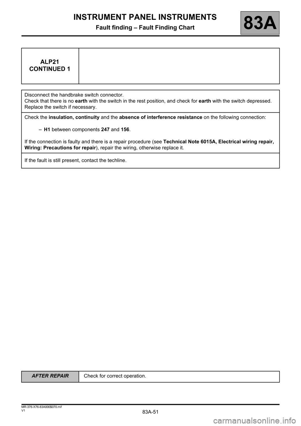
ALP21
CONTINUED 1
Disconnect the handbrake switch connector.
Check that there is no earth with the switch in the rest position, and check for earth with the switch depressed.
Replace the switch if necessary.
Check the insulation, continuity and the absence of interference resistance on the following connection:
–H1 between components 247 and 156.
If the connection is faulty and there is a repair procedure (see Technical Note 6015A, Electrical wiring repair,
Wiring: Precautions for repair), repair the wiring, otherwise replace it.
If the fault is still present, contact the techline.
Page 52 of 59
83A-52
AFTER REPAIRCheck for correct operation.
V1 MR-376-X76-83A000$070.mif
INSTRUMENT PANEL INSTRUMENTS
Fault finding – Fault Finding Chart83A
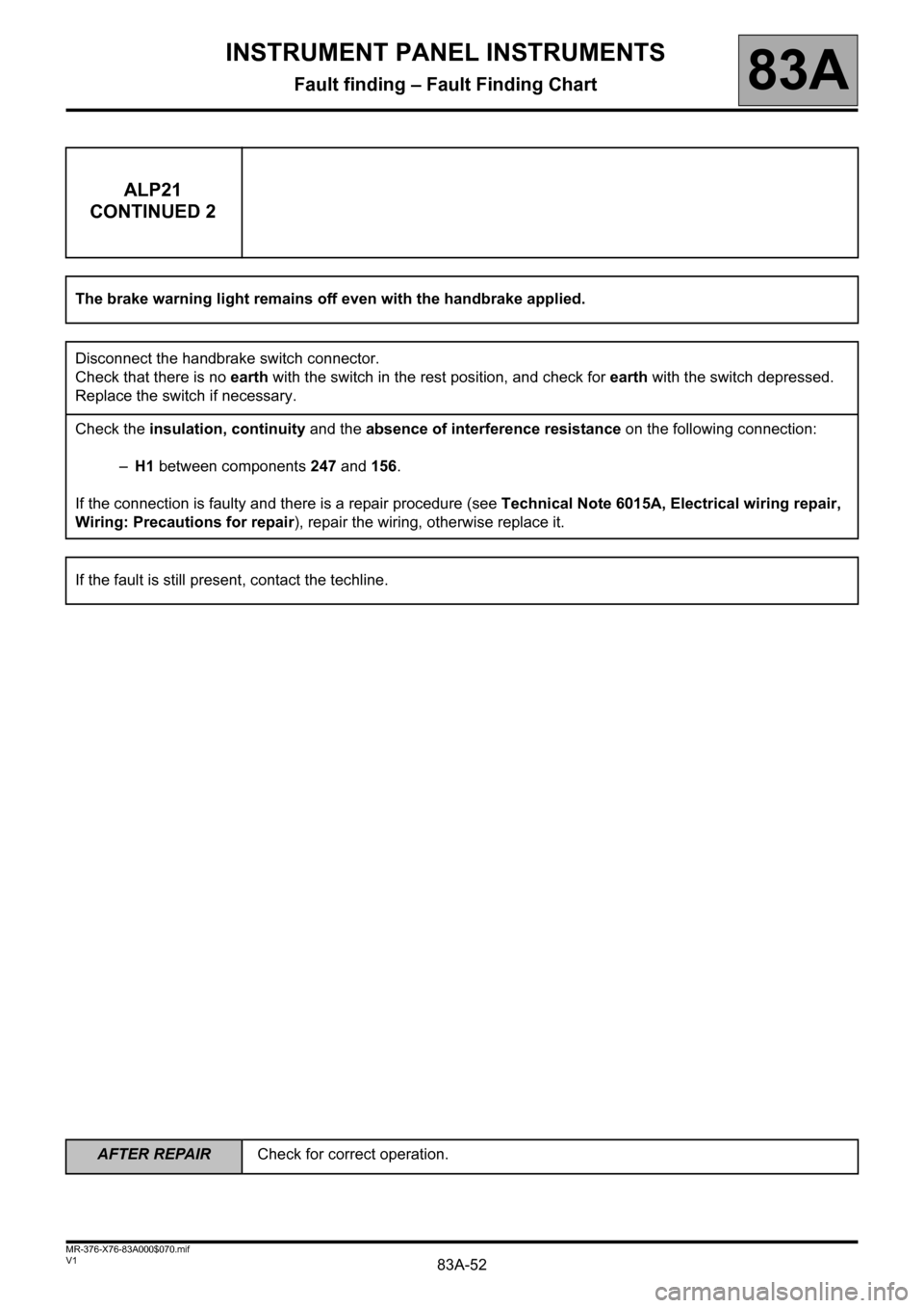
ALP21
CONTINUED 2
The brake warning light remains off even with the handbrake applied.
Disconnect the handbrake switch connector.
Check that there is no earth with the switch in the rest position, and check for earth with the switch depressed.
Replace the switch if necessary.
Check the insulation, continuity and the absence of interference resistance on the following connection:
–H1 between components 247 and 156.
If the connection is faulty and there is a repair procedure (see Technical Note 6015A, Electrical wiring repair,
Wiring: Precautions for repair), repair the wiring, otherwise replace it.
If the fault is still present, contact the techline.
Page 53 of 59
83A-53
AFTER REPAIRCheck for correct operation.
V1 MR-376-X76-83A000$070.mif
INSTRUMENT PANEL INSTRUMENTS
Fault finding – Fault Finding Chart83A
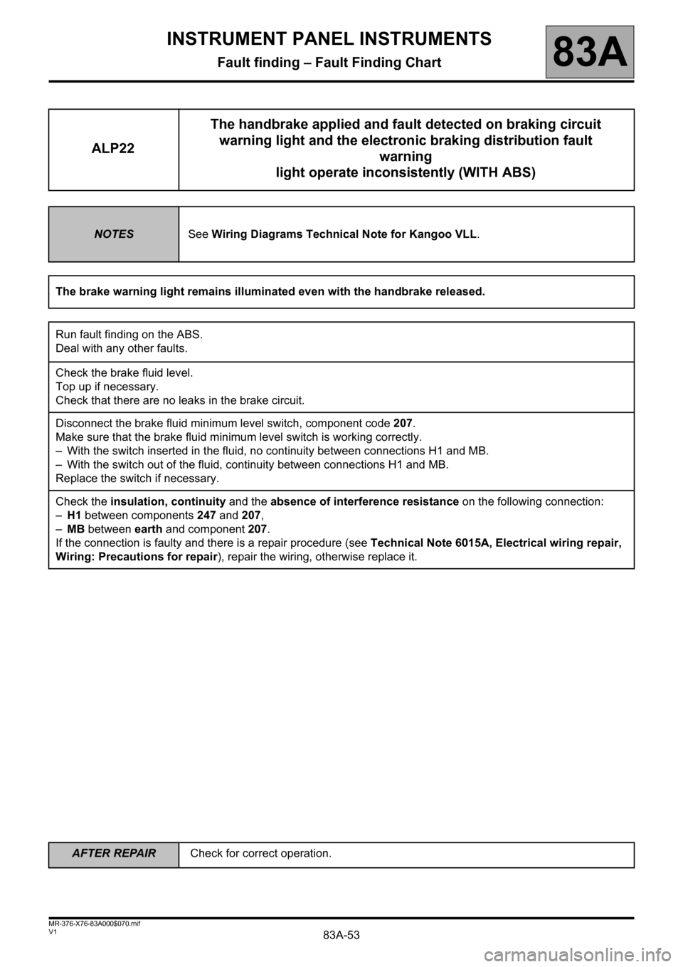
ALP22The handbrake applied and fault detected on braking circuit
warning light and the electronic braking distribution fault
warning
light operate inconsistently (WITH ABS)
NOTESSee Wiring Diagrams Technical Note for Kangoo VLL.
The brake warning light remains illuminated even with the handbrake released.
Run fault finding on the ABS.
Deal with any other faults.
Check the brake fluid level.
Top up if necessary.
Check that there are no leaks in the brake circuit.
Disconnect the brake fluid minimum level switch, component code 207.
Make sure that the brake fluid minimum level switch is working correctly.
– With the switch inserted in the fluid, no continuity between connections H1 and MB.
– With the switch out of the fluid, continuity between connections H1 and MB.
Replace the switch if necessary.
Check the insulation, continuity and the absence of interference resistance on the following connection:
–H1 between components 247 and 207,
–MB between earth and component 207.
If the connection is faulty and there is a repair procedure (see Technical Note 6015A, Electrical wiring repair,
Wiring: Precautions for repair), repair the wiring, otherwise replace it.
Page 54 of 59
83A-54
AFTER REPAIRCheck for correct operation.
V1 MR-376-X76-83A000$070.mif
INSTRUMENT PANEL INSTRUMENTS
Fault finding – Fault Finding Chart83A
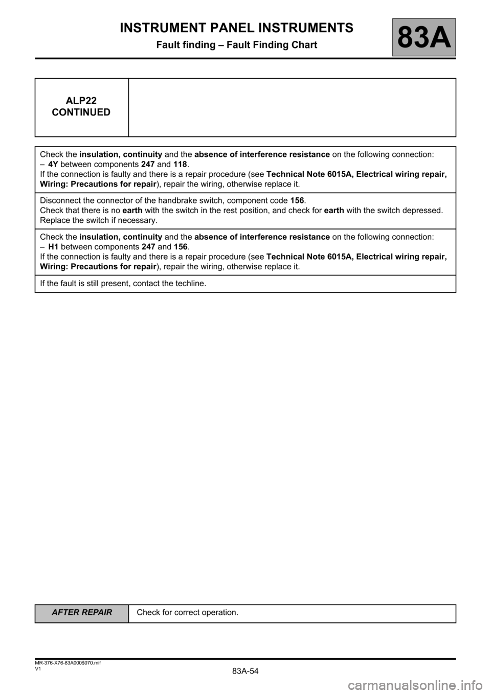
ALP22
CONTINUED
Check the insulation, continuity and the absence of interference resistance on the following connection:
–4Y between components 247 and 118.
If the connection is faulty and there is a repair procedure (see Technical Note 6015A, Electrical wiring repair,
Wiring: Precautions for repair), repair the wiring, otherwise replace it.
Disconnect the connector of the handbrake switch, component code 156.
Check that there is no earth with the switch in the rest position, and check for earth with the switch depressed.
Replace the switch if necessary.
Check the insulation, continuity and the absence of interference resistance on the following connection:
–H1 between components 247 and 156.
If the connection is faulty and there is a repair procedure (see Technical Note 6015A, Electrical wiring repair,
Wiring: Precautions for repair), repair the wiring, otherwise replace it.
If the fault is still present, contact the techline.