RENAULT KANGOO 2013 X61 / 2.G Petrol V42 Injection User Guide
Manufacturer: RENAULT, Model Year: 2013, Model line: KANGOO, Model: RENAULT KANGOO 2013 X61 / 2.GPages: 279, PDF Size: 1.29 MB
Page 11 of 279
17B-11V2 MR-376-X76-17B050$050.mif
PETROL INJECTION
Fault finding – Features17B
V42 Injection
Program No.: 2A
Vdiag No.: 04, 05, 06,
14, 16, 18
Engine temperature management
The engine is cooled by a 2-speed fan assembly.
To cool the engine, the first speed of the fan assembly is activated if the coolant temperature exceeds 99°C or 94°C
(F4R400/402/403 engines), then the second speed is activated if the temperature exceeds the 102°C or 97°C
(F4R400/402/403 engines). A "very high temperature" warning light illuminates on the instrument panel if the
temperature exceeds 118°C or 113°C (F4R400/402/403 engines).
Page 12 of 279
17B-12V2 MR-376-X76-17B050$060.mif
17B
V42 Injection
Program No.: 2A
Vdiag No.: 04, 05, 06,
14, 16, 18
OPERATIONS FOR REPLACING OR REPROGRAMMING THE COMPUTER
Procedure to be applied before replacement
This procedure must be applied before replacing or reprogramming the injection computer (see MR 388 (Logan and
Sandero), MR 451 (Duster), MR 423 (Thalia 2/Symbol 2), MR 430 (Clio II F 6), or MR 374 (Kangoo VLL),
Mechanical, 17B, Petrol injection, Petrol injection computer: Removal - Refitting).
– Connect the diagnostic tool (mains or cigarette lighter supply).
– Save the data by running command: SC003 Save computer data. In the event of a fault, contact the Techline.
– In the event of a replacement, note the vehicle VIN code using command ID008 VIN code.
– Switch on vehicle + after ignition feed and wait until the coolant temperature is less than 70°C and the air
temperature is less than 50°C. Consult parameter PR064 Coolant temperature and PR059 Air temperature.
– Apply the programming or reprogramming operations described in Technical Note 3585A Computer
(re)programming procedure.
Procedure to be applied after repair:
This procedure must be applied after replacing or reprogramming the computer.
Entering the saved data
– enter the saved data by running command SC001 Write saved data.
Programming the VIN code
– Display the identifier ID008
If the VIN is not entered, enter the VIN. using command VP010 Enter VIN. IMPORTANT:
– The computer permanently stores the immobilisation function code. It is forbidden to perform tests with
computers borrowed from the Parts Department or from another vehicle.
– Connect a battery charger and switch on the vehicle + after ignition feed.
– Switch off all the electrical consumers (lights, interior lighting, air conditioning, radio, etc.).
IMPORTANT:
It is necessary to respect these temperature values in order to carry out the computer programming or
reprogramming operations.
IMPORTANT:
After (re)programming the computer, switch off the + after ignition feed and wait for the loss of communication
message to appear on the diagnostic tool, if the message does not appear, wait for 9 minutes.
Failure to follow this procedure may cause the computer data to be corrupted.
PETROL INJECTION
Fault finding – Replacement of components
Page 13 of 279
17B-13V2 MR-376-X76-17B050$060.mif
PETROL INJECTION
Fault finding – Replacement of components17B
V42 Injection
Program No.: 2A
Vdiag No.: 04, 05, 06,
14, 16, 18
Programming the alcohol level
– Put the vehicle under + after ignition and wait for the value of parameter PR064 Coolant temperature to be greater
than or equal to 80°C.
– There must be no present or stored faults.
– With the ignition on and engine stopped, note the value of PR743 Estimated alcohol level in the tank.
– Carry out resetting using command RZ064 Programming the alcohol level.
– Start the engine and allow the engine to idle for 5 minutes.
– Check the correct programming using parameter PR743; its value must have changed.
– If programming was not performed correctly, repeat the operation from the start.
– If the fault is still present, contact the Techline.
Injection computer initialisation
Start and stop the engine to initialise the computer and wait for the loss of communication message to appear on the
diagnostic tool. If the message does not appear, wait for 9 minutes.
The computer is automatically configured according to the sensors and options present on the vehicle.
If the data were not saved before the operation, carry out the following operations:
– Programming the VIN code
– Enter the V.I.N. using command VP010 Enter VIN.
– Injector programming
Program the injectors by accessing the sub-section entitled Injector replacement operations.
– Programming the TDC sensor
Program the TDC sensor by accessing the sub-section entitled TDC (Top Dead Centre) sensor replacement
operations.
– Programming the motorised throttle
Program the motorised throttle by accessing the sub-section entitled Throttle valve replacement operations.
– Injection computer initialisation
Start and stop the engine to initialise the computer and wait for the loss of communication message to appear on the
diagnostic tool, if the message does not appear, wait for 9 minutes.
The computer is automatically configured according to the sensors and options present on the vehicle.
Page 14 of 279
17B-14V2 MR-376-X76-17B050$060.mif
PETROL INJECTION
Fault finding – Replacement of components17B
V42 Injection
Program No.: 2A
Vdiag No.: 04, 05, 06,
14, 16, 18
THROTTLE VALVE REPLACEMENT OPERATIONS
– When replacing the inlet throttle valve, switch on the vehicle + after ignition feed, after replacing the part.
– Carry out resetting using command RZ031 Throttle stop programming.
– Switch off the ignition. The inlet valve will run a new programming procedure whilst maintaining the supply (power
latch) due to the reinitialisation phase.
– Check that the programming is correct using status ET051 Throttle stop programming, it must be at 1.
If programming was not performed correctly, repeat the operation from the start.
– If the fault is still present, contact the Techline.
OPERATIONS FOR REPLACING THE BRAKE PEDAL SWITCH
– When replacing the brake pedal switch, switch on the vehicle + after ignition feed, after replacing the part.
– Check that the switch statuses change as follows, when the brake pedal is activated:
–ET039 Brake pedal = 1 and ET799 Brake Wire Contact = 1 when the brake pedal is released
–ET039 Brake pedal = 2 and ET799 Brake Wire Contact = 2 when the brake pedal is depressed
OPERATIONS FOR REPLACING THE TDC (TOP DEAD CENTRE) SENSOR
– Switch on the vehicle + after ignition feed,
– Carry out resetting using command RZ037 Flywheel target programming.
Operation for Programming
– Decelerate a first time with injection cut-off (i.e. feet off the brake, accelerator and clutch pedals) between 3500 and
3000 rpm, in 3rd gear for a BVM* for at least 3 seconds.
– Decelerate a second time with injection cut-off (i.e. feet off the brake, accelerator and clutch pedals) between 2400
and 2000 rpm, in 3rd gear for a BVM* for at least 14 seconds (K4M, K7M engine) or 3 seconds (D4D, F4R, K4M
engine of Duster).
*BVM: Manual gearbox
The programming was successful when status ET089 Flywheel target programming has the value1.
Page 15 of 279
17B-15V2 MR-376-X76-17B050$060.mif
PETROL INJECTION
Fault finding – Replacement of components17B
V42 Injection
Program No.: 2A
Vdiag No.: 04, 05, 06,
14, 16, 18
OPERATIONS FOR REPLACING THE INJECTORS
– Switch on the vehicle + after ignition feed after replacing the part.
Carry out resetting using command RZ033 Richness regulation programming.
– Switch off the ignition.
A power latch is necessary to save the reset data.
– Switch on the vehicle + after ignition feed and check the values of the following parameters:
PR624 Richness regulation programming offset
PR625 Richness regulation programming gain
– Test the injectors using the following commands:
AC005 Cylinder 1 injector
AC006 Cylinder 2 injector
AC007 Cylinder 3 injector
AC008 Cylinder 4 injector.
OPERATIONS OF REPLACING THE CAMSHAFT DEPHASER SOLENOID VALVE
– Switch on the vehicle + after ignition feed.
– Reset to zero using command RZ001 Fault memory.
– Start the engine and allow the engine to idle for at least 60 seconds.
– Switch off the engine.
– Wait for the end of the power-latch phase and switch on the vehicle + after ignition.
– Check that ET845 Camshaft dephaser s.v.* programming is PERFORMED.
*s.v.: solenoid valve
Page 16 of 279
17B-16V2 MR-376-X76-17B050$070.mif
17B
V42 Injection
Program No.: 2A
Vdiag No.: 04, 05, 06,
14, 16, 18
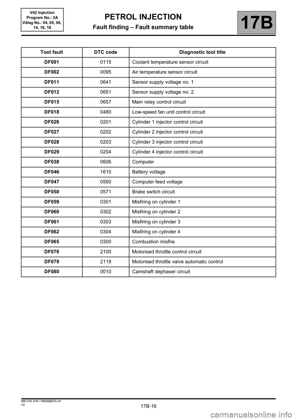
Tool fault DTC code Diagnostic tool title
DF0010115 Coolant temperature sensor circuit
DF0020095 Air temperature sensor circuit
DF0110641 Sensor supply voltage no. 1
DF0120651 Sensor supply voltage no. 2
DF0150657 Main relay control circuit
DF0180480 Low-speed fan unit control circuit
DF0260201 Cylinder 1 injector control circuit
DF0270202 Cylinder 2 injector control circuit
DF0280203 Cylinder 3 injector control circuit
DF0290204 Cylinder 4 injector control circuit
DF0380606 Computer
DF0461610 Battery voltage
DF0470560 Computer feed voltage
DF0500571 Brake switch circuit
DF0590301 Misfiring on cylinder 1
DF0600302 Misfiring on cylinder 2
DF0610303 Misfiring on cylinder 3
DF0620304 Misfiring on cylinder 4
DF0650300 Combustion misfire
DF0782100 Motorised throttle control circuit
DF0792119 Motorised throttle valve automatic control
DF0800010 Camshaft dephaser circuit
PETROL INJECTION
Fault finding – Fault summary table
Page 17 of 279
17B-17V2 MR-376-X76-17B050$070.mif
PETROL INJECTION
Fault finding – Fault summary table17B
V42 Injection
Program No.: 2A
Vdiag No.: 04, 05, 06,
14, 16, 18
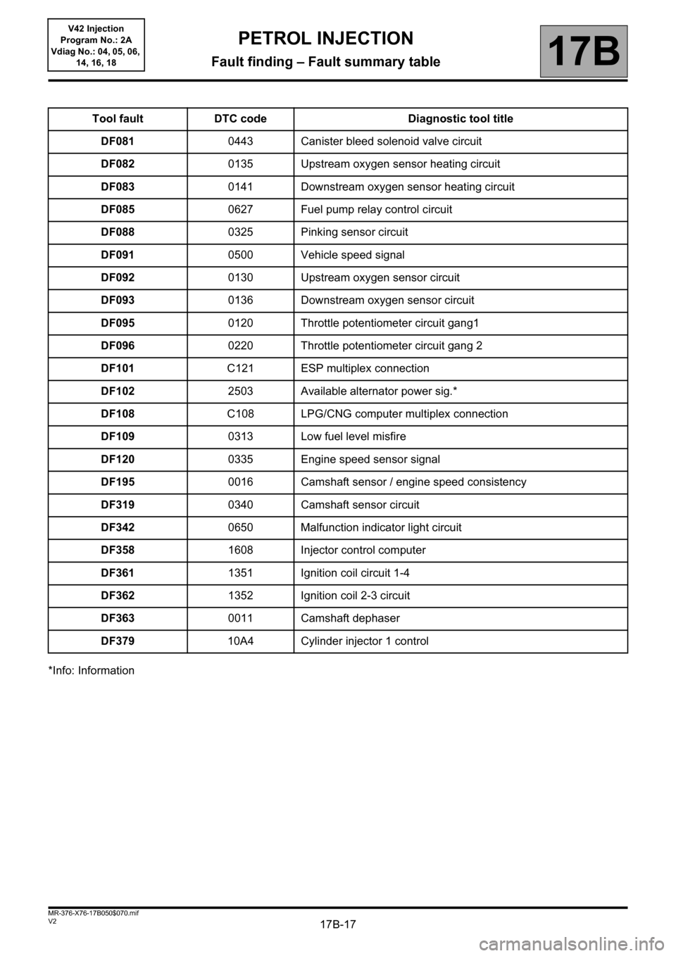
*Info: InformationTool fault DTC code Diagnostic tool title
DF0810443 Canister bleed solenoid valve circuit
DF0820135 Upstream oxygen sensor heating circuit
DF0830141 Downstream oxygen sensor heating circuit
DF0850627 Fuel pump relay control circuit
DF0880325 Pinking sensor circuit
DF0910500 Vehicle speed signal
DF0920130 Upstream oxygen sensor circuit
DF0930136 Downstream oxygen sensor circuit
DF0950120 Throttle potentiometer circuit gang1
DF0960220 Throttle potentiometer circuit gang 2
DF101C121 ESP multiplex connection
DF1022503 Available alternator power sig.*
DF108C108 LPG/CNG computer multiplex connection
DF1090313 Low fuel level misfire
DF1200335 Engine speed sensor signal
DF1950016 Camshaft sensor / engine speed consistency
DF3190340 Camshaft sensor circuit
DF3420650 Malfunction indicator light circuit
DF3581608 Injector control computer
DF3611351 Ignition coil circuit 1-4
DF3621352 Ignition coil 2-3 circuit
DF3630011 Camshaft dephaser
DF37910A4 Cylinder injector 1 control
Page 18 of 279
17B-18V2 MR-376-X76-17B050$070.mif
PETROL INJECTION
Fault finding – Fault summary table17B
V42 Injection
Program No.: 2A
Vdiag No.: 04, 05, 06,
14, 16, 18
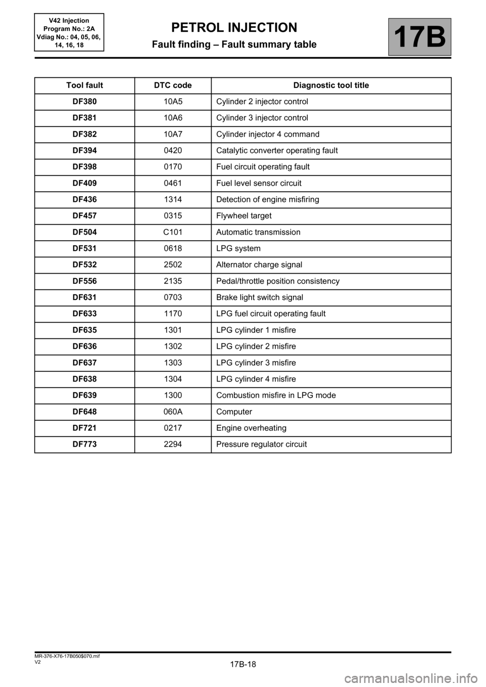
Tool fault DTC code Diagnostic tool title
DF38010A5 Cylinder 2 injector control
DF38110A6 Cylinder 3 injector control
DF38210A7 Cylinder injector 4 command
DF3940420 Catalytic converter operating fault
DF3980170 Fuel circuit operating fault
DF4090461 Fuel level sensor circuit
DF4361314 Detection of engine misfiring
DF4570315 Flywheel target
DF504C101 Automatic transmission
DF5310618 LPG system
DF5322502 Alternator charge signal
DF5562135 Pedal/throttle position consistency
DF6310703 Brake light switch signal
DF6331170 LPG fuel circuit operating fault
DF6351301 LPG cylinder 1 misfire
DF6361302 LPG cylinder 2 misfire
DF6371303 LPG cylinder 3 misfire
DF6381304 LPG cylinder 4 misfire
DF6391300 Combustion misfire in LPG mode
DF648060A Computer
DF7210217 Engine overheating
DF7732294 Pressure regulator circuit
Page 19 of 279
17B-19V2 MR-376-X76-17B050$070.mif
PETROL INJECTION
Fault finding – Fault summary table17B
V42 Injection
Program No.: 2A
Vdiag No.: 04, 05, 06,
14, 16, 18
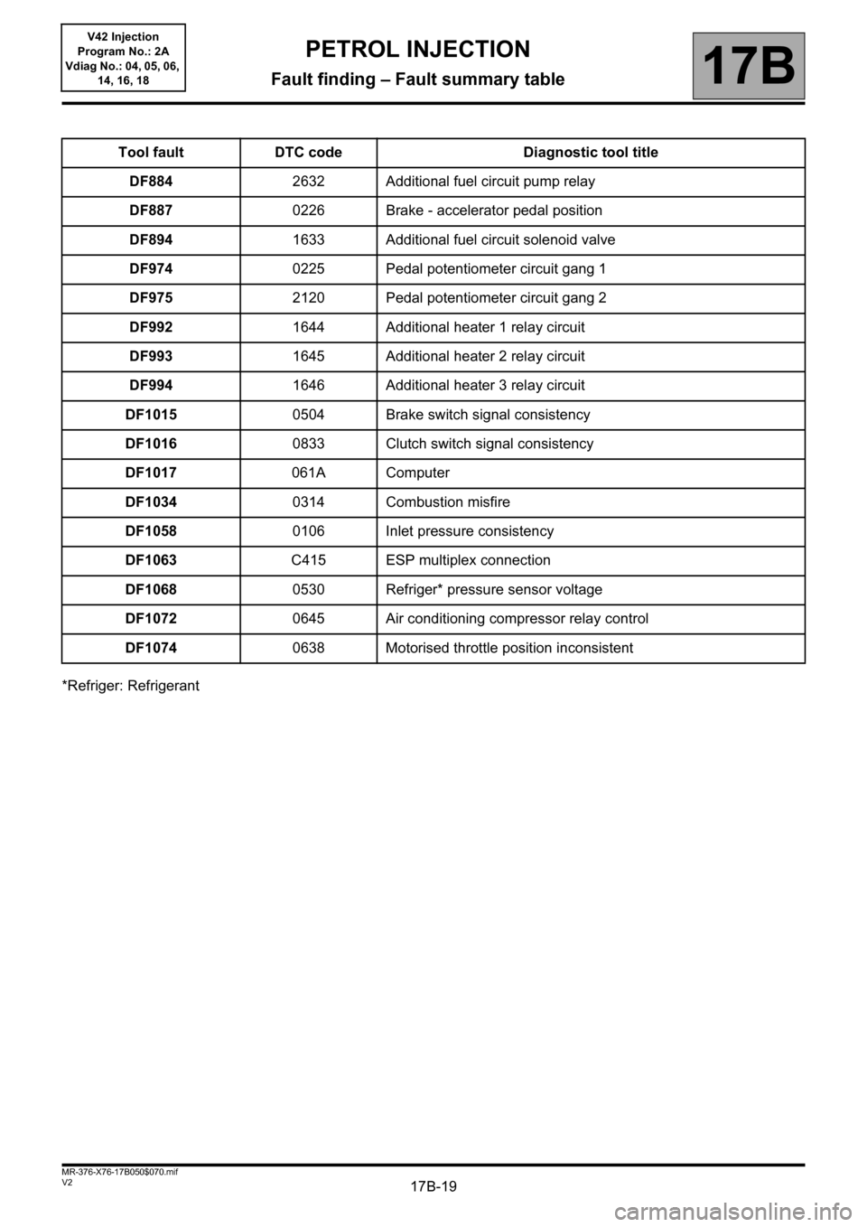
*Refriger: RefrigerantTool fault DTC code Diagnostic tool title
DF8842632 Additional fuel circuit pump relay
DF8870226 Brake - accelerator pedal position
DF8941633 Additional fuel circuit solenoid valve
DF9740225 Pedal potentiometer circuit gang 1
DF9752120 Pedal potentiometer circuit gang 2
DF9921644 Additional heater 1 relay circuit
DF9931645 Additional heater 2 relay circuit
DF9941646 Additional heater 3 relay circuit
DF10150504 Brake switch signal consistency
DF10160833 Clutch switch signal consistency
DF1017061A Computer
DF10340314 Combustion misfire
DF10580106 Inlet pressure consistency
DF1063C415 ESP multiplex connection
DF10680530 Refriger* pressure sensor voltage
DF10720645 Air conditioning compressor relay control
DF10740638 Motorised throttle position inconsistent
Page 20 of 279
17B-20V2 MR-376-X76-17B050$070.mif
PETROL INJECTION
Fault finding – Fault summary table17B
V42 Injection
Program No.: 2A
Vdiag No.: 04, 05, 06,
14, 16, 18
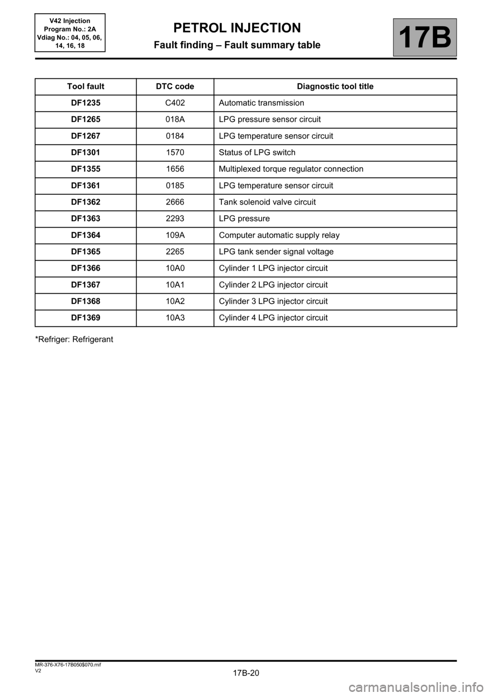
*Refriger: RefrigerantTool fault DTC code Diagnostic tool title
DF1235C402 Automatic transmission
DF1265018A LPG pressure sensor circuit
DF12670184 LPG temperature sensor circuit
DF13011570 Status of LPG switch
DF13551656 Multiplexed torque regulator connection
DF13610185 LPG temperature sensor circuit
DF13622666 Tank solenoid valve circuit
DF13632293 LPG pressure
DF1364109A Computer automatic supply relay
DF13652265 LPG tank sender signal voltage
DF136610A0 Cylinder 1 LPG injector circuit
DF136710A1 Cylinder 2 LPG injector circuit
DF136810A2 Cylinder 3 LPG injector circuit
DF136910A3 Cylinder 4 LPG injector circuit