RENAULT KANGOO 2013 X61 / 2.G Petrol V42 Injection Workshop Manual
Manufacturer: RENAULT, Model Year: 2013, Model line: KANGOO, Model: RENAULT KANGOO 2013 X61 / 2.GPages: 279, PDF Size: 1.29 MB
Page 271 of 279
17B-271
AFTER REPAIRCarry out a road test, then check with the diagnostic tool.
V2 MR-376-X76-17B050$180.mif
PETROL INJECTION
Fault finding – Tests17B
V42 Injection
Program No.: 2A
Vdiag No.: 04, 05, 06,
14, 16, 18
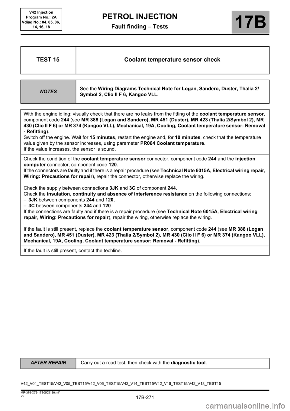
TEST 15 Coolant temperature sensor check
NOTESSee the Wiring Diagrams Technical Note for Logan, Sandero, Duster, Thalia 2/
Symbol 2, Clio II F 6, Kangoo VLL.
With the engine idling: visually check that there are no leaks from the fitting of the coolant temperature sensor,
component code 244 (see MR 388 (Logan and Sandero), MR 451 (Duster), MR 423 (Thalia 2/Symbol 2), MR
430 (Clio II F 6) or MR 374 (Kangoo VLL), Mechanical, 19A, Cooling, Coolant temperature sensor: Removal
- Refitting).
Switch off the engine. Wait for 15 minutes, restart the engine and, for 10 minutes, check that the temperature
value given by the sensor increases, using parameter PR064 Coolant temperature.
If the value increases, the sensor is sound.
Check the condition of the coolant temperature sensor connector, component code 244 and the injection
computer connector, component code 120.
If the connectors are faulty and if there is a repair procedure (see Technical Note 6015A, Electrical wiring repair,
Wiring: Precautions for repair), repair the connector, otherwise replace the wiring.
Check the supply between connections 3JK and 3C of component 244.
Check the insulation, continuity and absence of interference resistance on the following connections:
–3JK between components 244 and 120,
–3C between components 244 and 120.
If the connections are faulty and if there is a repair procedure (see Technical Note 6015A, Electrical wiring
repair, Wiring: Precautions for repair), repair the wiring, otherwise replace the wiring.
If the fault is still present, replace the coolant temperature sensor, component code 244 (see MR 388 (Logan
and Sandero), MR 451 (Duster), MR 423 (Thalia 2/Symbol 2), MR 430 (Clio II F 6) or MR 374 (Kangoo VLL),
Mechanical, 19A, Cooling, Coolant temperature sensor: Removal - Refitting).
If the fault is still present, contact the techline.
V42_V04_TEST15/V42_V05_TEST15/V42_V06_TEST15/V42_V14_TEST15/V42_V16_TEST15/V42_V18_TEST15
Page 272 of 279
17B-272
AFTER REPAIRCarry out a road test, then check with the diagnostic tool.
V2 MR-376-X76-17B050$180.mif
PETROL INJECTION
Fault finding – Tests17B
V42 Injection
Program No.: 2A
Vdiag No.: 04, 05, 06,
14, 16, 18
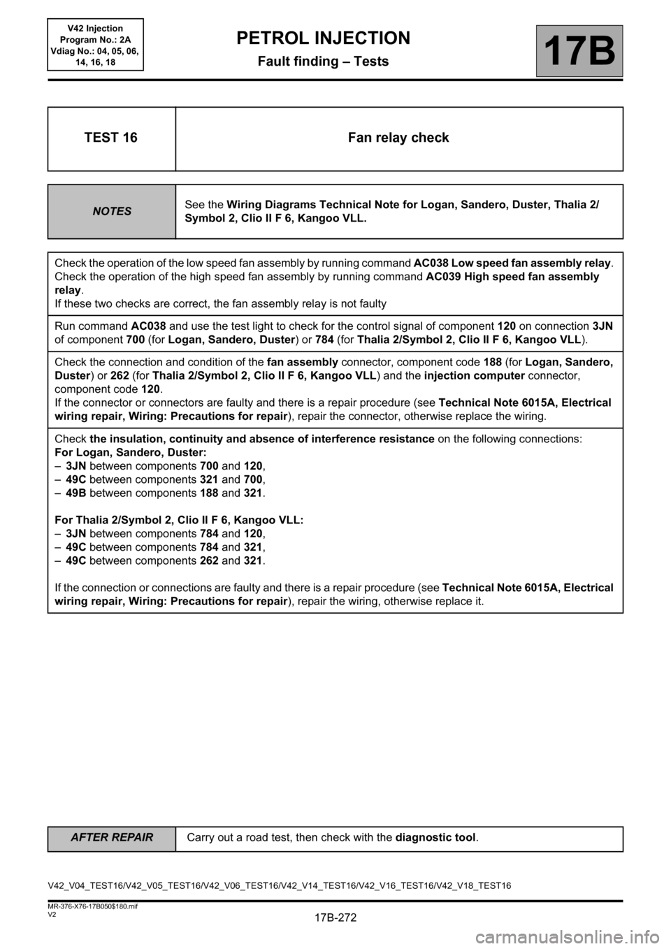
TEST 16 Fan relay check
NOTESSee the Wiring Diagrams Technical Note for Logan, Sandero, Duster, Thalia 2/
Symbol 2, Clio II F 6, Kangoo VLL.
Check the operation of the low speed fan assembly by running command AC038 Low speed fan assembly relay.
Check the operation of the high speed fan assembly by running command AC039 High speed fan assembly
relay.
If these two checks are correct, the fan assembly relay is not faulty
Run command AC038 and use the test light to check for the control signal of component 120 on connection 3JN
of component 700 (for Logan, Sandero, Duster) or 784 (for Thalia 2/Symbol 2, Clio II F 6, Kangoo VLL).
Check the connection and condition of the fan assembly connector, component code 188 (for Logan, Sandero,
Duster) or 262 (for Thalia 2/Symbol 2, Clio II F 6, Kangoo VLL) and the injection computer connector,
component code 120.
If the connector or connectors are faulty and there is a repair procedure (see Technical Note 6015A, Electrical
wiring repair, Wiring: Precautions for repair), repair the connector, otherwise replace the wiring.
Check the insulation, continuity and absence of interference resistance on the following connections:
For Logan, Sandero, Duster:
–3JN between components 700 and 120,
–49C between components 321 and 700,
–49B between components 188 and 321.
For Thalia 2/Symbol 2, Clio II F 6, Kangoo VLL:
–3JN between components 784 and 120,
–49C between components 784 and 321,
–49C between components 262 and 321.
If the connection or connections are faulty and there is a repair procedure (see Technical Note 6015A, Electrical
wiring repair, Wiring: Precautions for repair), repair the wiring, otherwise replace it.
V42_V04_TEST16/V42_V05_TEST16/V42_V06_TEST16/V42_V14_TEST16/V42_V16_TEST16/V42_V18_TEST16
Page 273 of 279
17B-273
AFTER REPAIRCarry out a road test, then check with the diagnostic tool.
V2 MR-376-X76-17B050$180.mif
PETROL INJECTION
Fault finding – Tests17B
V42 Injection
Program No.: 2A
Vdiag No.: 04, 05, 06,
14, 16, 18
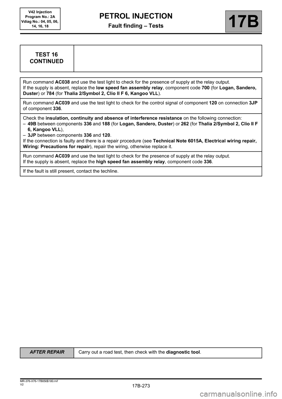
TEST 16
CONTINUED
Run command AC038 and use the test light to check for the presence of supply at the relay output.
If the supply is absent, replace the low speed fan assembly relay, component code 700 (for Logan, Sandero,
Duster) or 784 (for Thalia 2/Symbol 2, Clio II F 6, Kangoo VLL).
Run command AC039 and use the test light to check for the control signal of component 120 on connection 3JP
of component 336.
Check the insulation, continuity and absence of interference resistance on the following connection:
–49B between components 336 and 188 (for Logan, Sandero, Duster) or 262 (for Thalia 2/Symbol 2, Clio II F
6, Kangoo VLL),
–3JP between components 336 and 120.
If the connection is faulty and there is a repair procedure (see Technical Note 6015A, Electrical wiring repair,
Wiring: Precautions for repair), repair the wiring, otherwise replace it.
Run command AC039 and use the test light to check for the presence of supply at the relay output.
If the supply is absent, replace the high speed fan assembly relay, component code 336.
If the fault is still present, contact the techline.
Page 274 of 279

17B-274
AFTER REPAIRCarry out a road test, then check with the diagnostic tool.
V2 MR-376-X76-17B050$180.mif
PETROL INJECTION
Fault finding – Tests17B
V42 Injection
Program No.: 2A
Vdiag No.: 04, 05, 06,
14, 16, 18
TEST 17 Upstream O2 sensor check
NOTESSee the Wiring Diagrams Technical Note for Logan, Sandero, Duster, Thalia 2/
Symbol 2, Clio II F 6, Kangoo VLL.
Visually check the position and mounting of the upstream oxygen sensor (see MR 388 (Logan and Sandero), MR
451 (Duster), MR 423 (Thalia 2/Symbol 2), MR 430 (Clio II F 6) or MR 374 (Kangoo VLL), Mechanical, 17B,
Petrol injection, Oxygen sensors: Removal - Refitting).
With the engine warm, PR064 Coolant temperature >70°C, depress the accelerator pedal and check that PR098
Upstream oxygen sensor voltage varies correctly between: 20 mV < PR098 < 1395 mV. The variation must be
greater than 50 mV.
Check the connection and condition of the upstream oxygen sensor connector, component code 887 and of the
injection computer connector, component code 120.
If the connector or connectors are faulty and there is a repair procedure (see Technical Note 6015A, Electrical
wiring repair, Wiring: Precautions for repair), repair the connector, otherwise replace the wiring.
Check the insulation, continuity and absence of interference resistance on the following connection:
–3GH between components 887 and 120,
–3GK between components 887 and 120.
If the connection is faulty and there is a repair procedure (see Technical Note 6015A, Electrical wiring repair,
Wiring: Precautions for repair), repair the wiring, otherwise replace it.
V42_V04_TEST17/V42_V05_TEST17/V42_V06_TEST17/V42_V14_TEST17/V42_V16_TEST17/V42_V18_TEST17
Page 275 of 279
17B-275
AFTER REPAIRCarry out a road test, then check with the diagnostic tool.
V2 MR-376-X76-17B050$180.mif
PETROL INJECTION
Fault finding – Tests17B
V42 Injection
Program No.: 2A
Vdiag No.: 04, 05, 06,
14, 16, 18
TDC*: TOP DEAD CENTRE
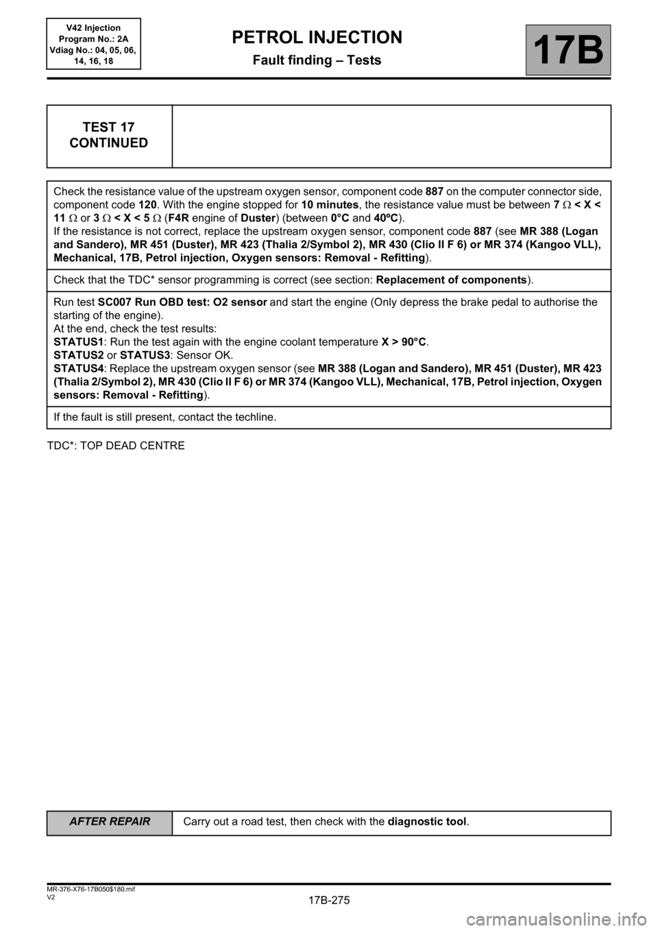
TEST 17
CONTINUED
Check the resistance value of the upstream oxygen sensor, component code 887 on the computer connector side,
component code 120. With the engine stopped for 10 minutes, the resistance value must be between 7< X <
11 or 3 < X < 5 (F4R engine of Duster) (between 0°C and 40ºC).
If the resistance is not correct, replace the upstream oxygen sensor, component code 887 (see MR 388 (Logan
and Sandero), MR 451 (Duster), MR 423 (Thalia 2/Symbol 2), MR 430 (Clio II F 6) or MR 374 (Kangoo VLL),
Mechanical, 17B, Petrol injection, Oxygen sensors: Removal - Refitting).
Check that the TDC* sensor programming is correct (see section: Replacement of components).
Run test SC007 Run OBD test: O2 sensor
and start the engine (Only depress the brake pedal to authorise the
starting of the engine).
At the end, check the test results:
STATUS1: Run the test again with the engine coolant temperature X > 90°C.
STATUS2 or STATUS3: Sensor OK.
STATUS4: Replace the upstream oxygen sensor (see MR 388 (Logan and Sandero), MR 451 (Duster), MR 423
(Thalia 2/Symbol 2), MR 430 (Clio II F 6) or MR 374 (Kangoo VLL), Mechanical, 17B, Petrol injection, Oxygen
sensors: Removal - Refitting).
If the fault is still present, contact the techline.
Page 276 of 279
17B-276
AFTER REPAIRCarry out a road test, then check with the diagnostic tool.
V2 MR-376-X76-17B050$180.mif
PETROL INJECTION
Fault finding – Tests17B
V42 Injection
Program No.: 2A
Vdiag No.: 04, 05, 06,
14, 16, 18
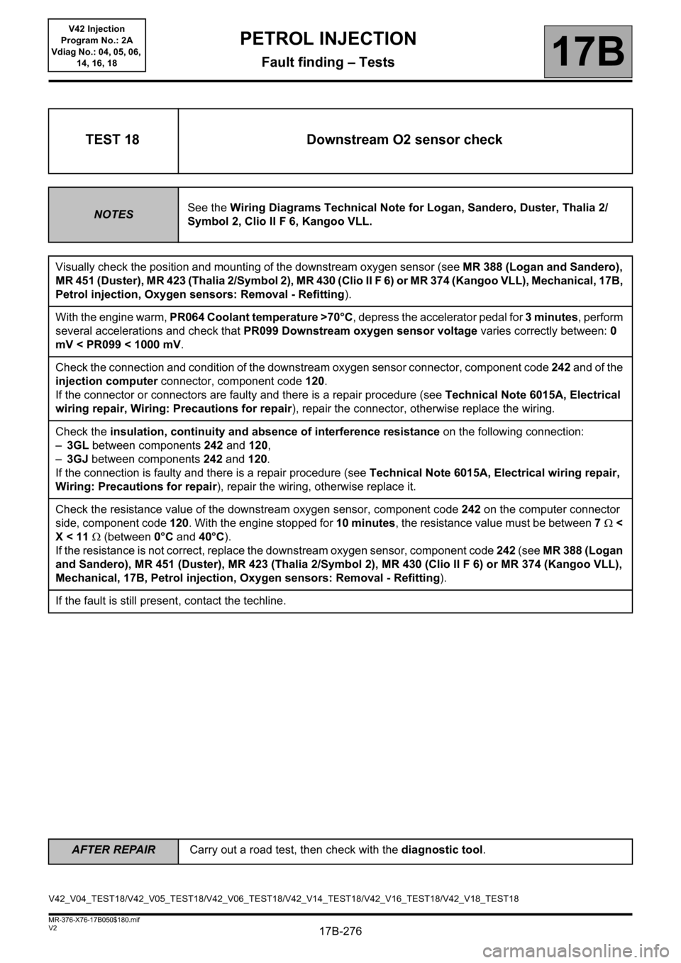
TEST 18 Downstream O2 sensor check
NOTESSee the Wiring Diagrams Technical Note for Logan, Sandero, Duster, Thalia 2/
Symbol 2, Clio II F 6, Kangoo VLL.
Visually check the position and mounting of the downstream oxygen sensor (see MR 388 (Logan and Sandero),
MR 451 (Duster), MR 423 (Thalia 2/Symbol 2), MR 430 (Clio II F 6) or MR 374 (Kangoo VLL), Mechanical, 17B,
Petrol injection, Oxygen sensors: Removal - Refitting).
With the engine warm, PR064 Coolant temperature >70°C, depress the accelerator pedal for 3 minutes, perform
several accelerations and check that PR099 Downstream oxygen sensor voltage varies correctly between: 0
mV < PR099 < 1000 mV.
Check the connection and condition of the downstream oxygen sensor connector, component code 242 and of the
injection computer connector, component code 120.
If the connector or connectors are faulty and there is a repair procedure (see Technical Note 6015A, Electrical
wiring repair, Wiring: Precautions for repair), repair the connector, otherwise replace the wiring.
Check the insulation, continuity and absence of interference resistance on the following connection:
–3GL between components 242 and 120,
–3GJ between components 242 and 120.
If the connection is faulty and there is a repair procedure (see Technical Note 6015A, Electrical wiring repair,
Wiring: Precautions for repair), repair the wiring, otherwise replace it.
Check the resistance value of the downstream oxygen sensor, component code 242 on the computer connector
side, component code 120. With the engine stopped for 10 minutes, the resistance value must be between 7<
X < 11 (between 0°C and 40°C).
If the resistance is not correct, replace the downstream oxygen sensor, component code 242 (see MR 388 (Logan
and Sandero), MR 451 (Duster), MR 423 (Thalia 2/Symbol 2), MR 430 (Clio II F 6) or MR 374 (Kangoo VLL),
Mechanical, 17B, Petrol injection, Oxygen sensors: Removal - Refitting).
If the fault is still present, contact the techline.
V42_V04_TEST18/V42_V05_TEST18/V42_V06_TEST18/V42_V14_TEST18/V42_V16_TEST18/V42_V18_TEST18
Page 277 of 279
17B-277
AFTER REPAIRCarry out a road test, then check with the diagnostic tool.
V2 MR-376-X76-17B050$180.mif
PETROL INJECTION
Fault finding – Tests17B
V42 Injection
Program No.: 2A
Vdiag No.: 04, 05, 06,
14, 16, 18
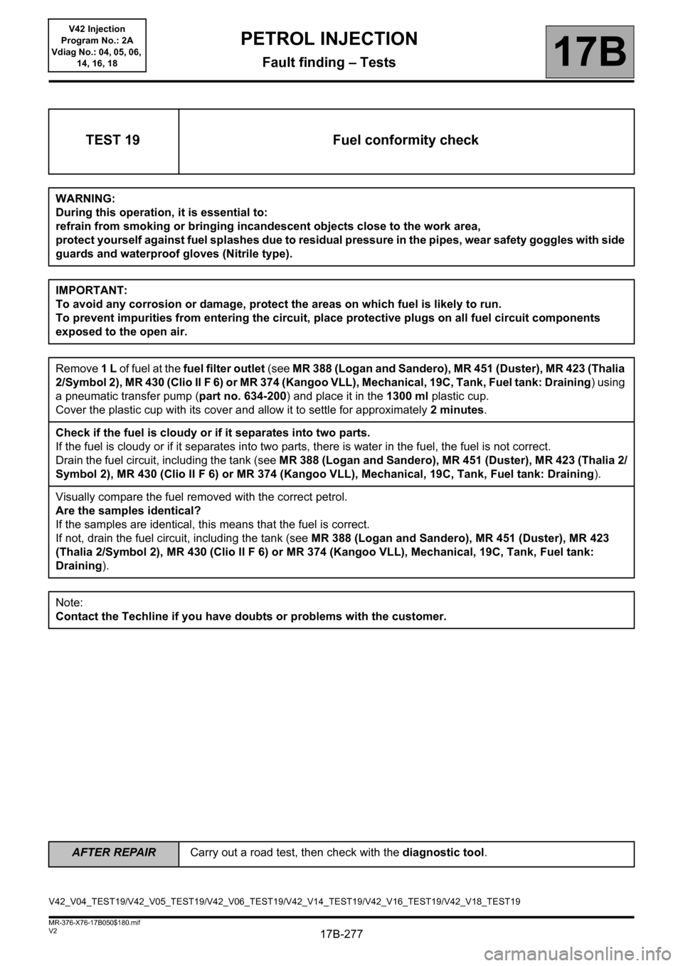
TEST 19 Fuel conformity check
WARNING:
During this operation, it is essential to:
refrain from smoking or bringing incandescent objects close to the work area,
protect yourself against fuel splashes due to residual pressure in the pipes, wear safety goggles with side
guards and waterproof gloves (Nitrile type).
IMPORTANT:
To avoid any corrosion or damage, protect the areas on which fuel is likely to run.
To prevent impurities from entering the circuit, place protective plugs on all fuel circuit components
exposed to the open air.
Remove 1 L of fuel at the fuel filter outlet (see MR 388 (Logan and Sandero), MR 451 (Duster), MR 423 (Thalia
2/Symbol 2), MR 430 (Clio II F 6) or MR 374 (Kangoo VLL), Mechanical, 19C, Tank, Fuel tank: Draining) using
a pneumatic transfer pump (part no. 634-200) and place it in the 1300 ml plastic cup.
Cover the plastic cup with its cover and allow it to settle for approximately 2 minutes.
Check if the fuel is cloudy or if it separates into two parts.
If the fuel is cloudy or if it separates into two parts, there is water in the fuel, the fuel is not correct.
Drain the fuel circuit, including the tank (see MR 388 (Logan and Sandero), MR 451 (Duster), MR 423 (Thalia 2/
Symbol 2), MR 430 (Clio II F 6) or MR 374 (Kangoo VLL), Mechanical, 19C, Tank, Fuel tank: Draining).
Visually compare the fuel removed with the correct petrol.
Are the samples identical?
If the samples are identical, this means that the fuel is correct.
If not, drain the fuel circuit, including the tank (see MR 388 (Logan and Sandero), MR 451 (Duster), MR 423
(Thalia 2/Symbol 2), MR 430 (Clio II F 6) or MR 374 (Kangoo VLL), Mechanical, 19C, Tank, Fuel tank:
Draining).
Note:
Contact the Techline if you have doubts or problems with the customer.
V42_V04_TEST19/V42_V05_TEST19/V42_V06_TEST19/V42_V14_TEST19/V42_V16_TEST19/V42_V18_TEST19
Page 278 of 279
17B-278
AFTER REPAIRCarry out a road test, then check with the diagnostic tool.
V2 MR-376-X76-17B050$180.mif
PETROL INJECTION
Fault finding – Tests17B
V42 Injection
Program No.: 2A
Vdiag No.: 04, 05, 06,
14, 16, 18
TDC*: Top Dead Centre
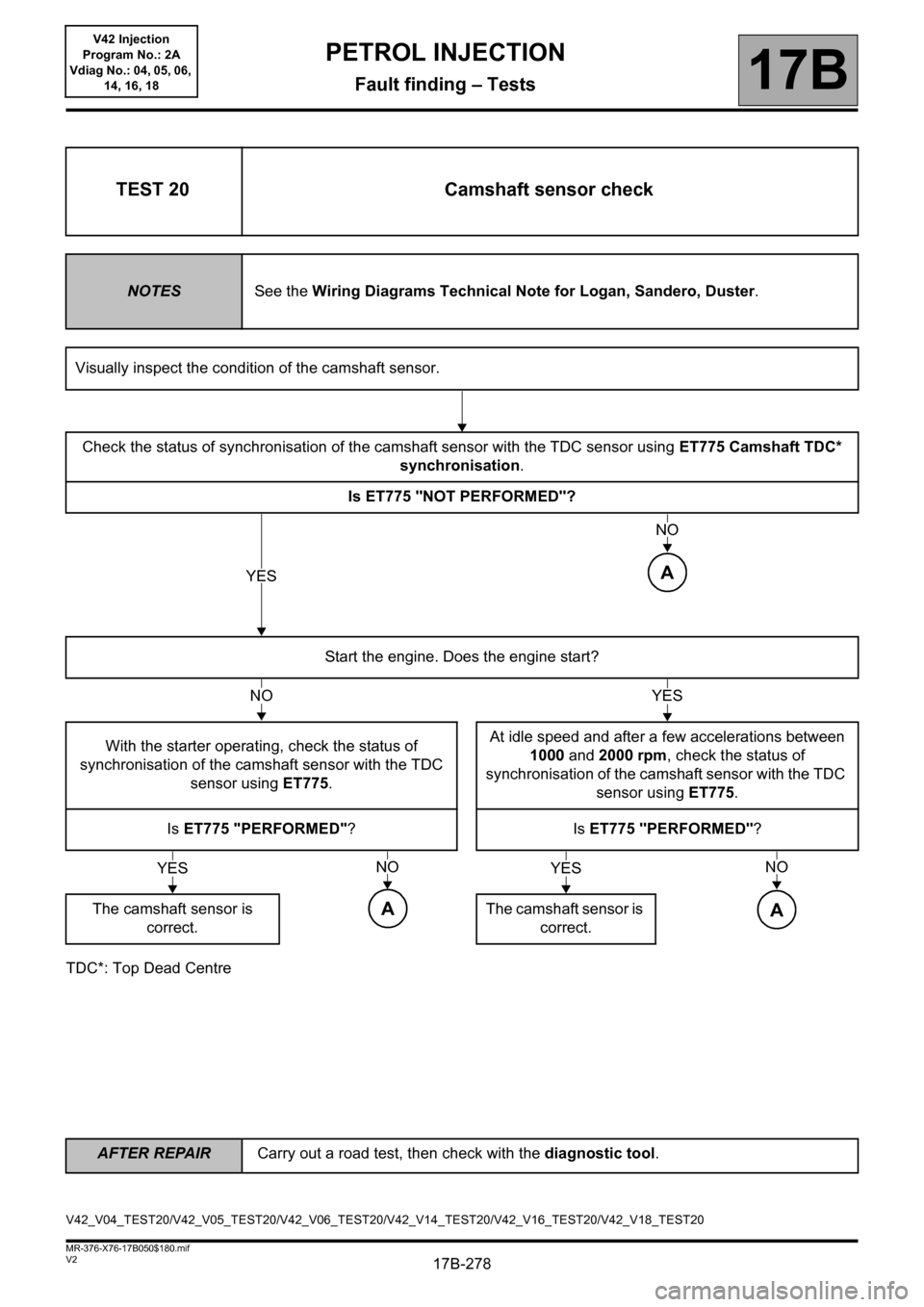
TEST 20 Camshaft sensor check
NOTESSee the Wiring Diagrams Technical Note for Logan, Sandero, Duster.
Visually inspect the condition of the camshaft sensor.
Check the status of synchronisation of the camshaft sensor with the TDC sensor using ET775 Camshaft TDC*
synchronisation.
Is ET775 "NOT PERFORMED"?
Start the engine. Does the engine start?
With the starter operating, check the status of
synchronisation of the camshaft sensor with the TDC
sensor using ET775.At idle speed and after a few accelerations between
1000 and 2000 rpm, check the status of
synchronisation of the camshaft sensor with the TDC
sensor using ET775.
Is ET775 "PERFORMED"?Is ET775 "PERFORMED"?
The camshaft sensor is
correct.The camshaft sensor is
correct.
YES
NO
A
NOYES
YESNO
A
YESNO
A
V42_V04_TEST20/V42_V05_TEST20/V42_V06_TEST20/V42_V14_TEST20/V42_V16_TEST20/V42_V18_TEST20
Page 279 of 279
17B-279
AFTER REPAIRCarry out a road test, then check with the diagnostic tool.
V2 MR-376-X76-17B050$180.mif
PETROL INJECTION
Fault finding – Tests17B
V42 Injection
Program No.: 2A
Vdiag No.: 04, 05, 06,
14, 16, 18
TEST 20
CONTINUED
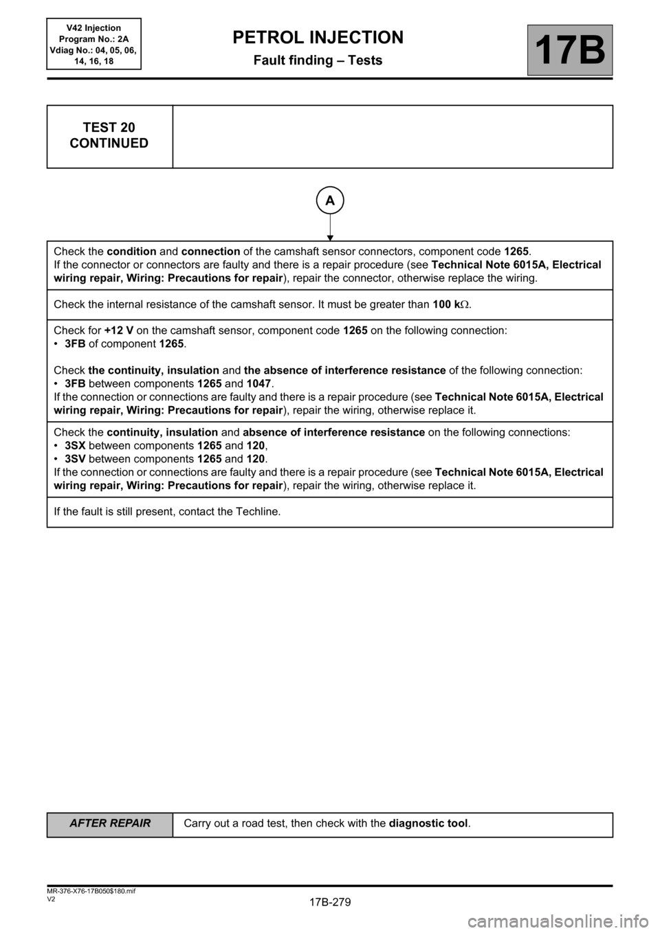
Check the condition and connection of the camshaft sensor connectors, component code 1265.
If the connector or connectors are faulty and there is a repair procedure (see Technical Note 6015A, Electrical
wiring repair, Wiring: Precautions for repair), repair the connector, otherwise replace the wiring.
Check the internal resistance of the camshaft sensor. It must be greater than 100 k.
Check for +12 V on the camshaft sensor, component code 1265 on the following connection:
•3FB of component 1265.
Check the continuity, insulation and the absence of interference resistance of the following connection:
•3FB between components 1265 and 1047.
If the connection or connections are faulty and there is a repair procedure (see Technical Note 6015A, Electrical
wiring repair, Wiring: Precautions for repair), repair the wiring, otherwise replace it.
Check the continuity, insulation and absence of interference resistance on the following connections:
•3SX between components 1265 and 120,
•3SV between components 1265 and 120.
If the connection or connections are faulty and there is a repair procedure (see Technical Note 6015A, Electrical
wiring repair, Wiring: Precautions for repair), repair the wiring, otherwise replace it.
If the fault is still present, contact the Techline.
A