RENAULT KOLEOS 2018 Owners Manual
Manufacturer: RENAULT, Model Year: 2018, Model line: KOLEOS, Model: RENAULT KOLEOS 2018Pages: 332, PDF Size: 8.91 MB
Page 131 of 332
2.27
ENVIRONMENT
Emissions
Your vehicle has been designed to
emit fewer greenhouse gases (CO2)
while in use, and therefore to consume
less fuel (eg. 140 g/km, equivalent to
5.3 l/100 km for a diesel vehicle).
Our vehicles are also equipped with a
particle filter system including a cata-
lytic converter, an oxygen sensor and
an active carbon filter (the latter pre-
vents vapour from the fuel tank being
released into the open air).
For certain diesel vehicles, this system
also has a particle filter to reduce the
volume of soot particles emitted.
Please make your own
contribution towards
protecting the environment
too
– Worn parts replaced in the course of routine vehicle maintenance (vehi-
cle battery, oil filter, air filter, batter-
ies, etc.) and oil containers (empty or
filled with used oil) must be disposed
of through specialist organisations. – At the end of the vehicle’s service
life, it should be sent to approved
centres to ensure that it is recycled.
– In all cases, comply with local legis- lation.
Recycling
Your vehicle is 85% recyclable and
95% recoverable.
To achieve these objectives, many of
the vehicle components have been de-
signed to enable them to be recycled.
The materials and structures have
been carefully designed to allow these
components to be easily removed and
reprocessed by specialist companies.
In order to preserve raw material re-
sources, this vehicle incorporates nu-
merous parts made from recycled plas-
tics or renewable materials (vegetable
or animal-derived materials such as
cotton or wool).
Your vehicle has been designed with
respect for the environment in mind for
its entire service life: during production,
use and at the end of its life.
This commitment is illustrated by the
Renault eco² signature.Manufacture
Your vehicle has been manufactured at
a factory which complies with a policy
to reduce the environmental impact
on the surrounding areas (reduction of
water and energy consumption, visual
and noise pollution, atmospheric emis-
sions and waste water; sorting and re-
using waste).
Page 132 of 332
2.28
TYRE PRESSURE MONITORING SYSTEM (1/3)
Resetting the standard level
for the tyre pressures
This should be done:
– when the standard tyre pressure needs to be changed to adapt to
usage conditions (empty, carrying a
load, motorway driving, etc.);
– after swapping a wheel (however this practice is not recommended);
– after changing a wheel.
It should always be done after checking
the tyre pressure of all four tyres when
cold.
Tyre pressures must correspond to the
current usage of the vehicle (empty,
carrying a load, motorway driving, etc.).
213
Resetting can also be done from the
multifunction screen 3 if your vehi-
cle is fitted with a navigation system.
Select the menu “Vehicle”, “Tyre
pressure”.
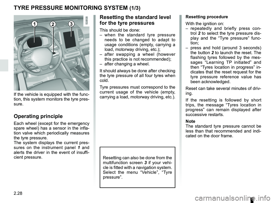
If the vehicle is equipped with the func-
tion, this system monitors the tyre pres-
sure.
Operating principle
Each wheel (except for the emergency
spare wheel) has a sensor in the infla-
tion valve which periodically measures
the tyre pressure.
The system displays the current pres-
sures on the instrument panel 1 and
alerts the driver in the event of insuffi-
cient pressure. Resetting procedure
With the ignition on:
– repeatedly and briefly press con-
trol 2 to select the tyre pressure dis-
play and the “Tyre pressure” func-
tion;
– press and hold (around 3 seconds) the button 2 to launch the reset. The
flashing tyres followed by the mes-
sages “Learning TP initiated” and
then “Tyres location in progress” in-
dicates that the reset request for the
tyre pressure reference value has
been acknowledged.
Reset can take several minutes of driv-
ing.
If the resetting is followed by short
trips, the message “Tyres location in
progress” can remain displayed after
successive restarts.
Note
The standard tyre pressure cannot be
less than that recommended and indi-
cated on the door frame.
Page 133 of 332
2.29
TYRE PRESSURE MONITORING SYSTEM (2/3)
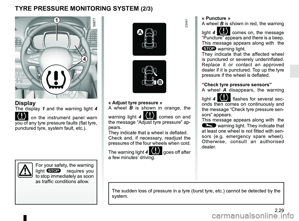
Display
The display 1 and the warning light 4
on the instrument panel warn
you of any tyre pressure faults (flat tyre,
punctured tyre, system fault, etc.).
« Puncture »
A wheel B is shown in red, the warning
light 4
comes on, the message
“Puncture” appears and there is a beep.
This message appears along with the
® warning light.
They indicate that the affected wheel
is punctured or severely underinflated.
Replace it or contact an approved
dealer if it is punctured. Top up the tyre
pressure if the wheel is deflated.
“Check tyre pressure sensors”
A wheel A disappears, the warning
light 4
flashes for several sec-
onds then comes on continuously and
the message “Check tyre pressure sen-
sors” appears.
This message appears along with the
© warning light. They indicate that
at least one wheel is not fitted with sen-
sors (e.g. emergency spare wheel).
Otherwise, consult an authorised
dealer.
« Adjust tyre pressure »
A wheel B
is shown in orange, the
warning light 4
comes on and
the message “Adjust tyre pressure” ap-
pears.
They indicate that a wheel is deflated.
Check and, if necessary, readjust the
pressures of the four wheels when cold.
The warning light 4
goes off after
a few minutes’ driving.
A
B
1
For your safety, the warning
light
® requires you
to stop immediately as soon
as traffic conditions allow.
The sudden loss of pressure in a tyre (burst tyre, etc.) cannot be det\
ected by the
system.
4
Page 134 of 332
2.30
Replacing wheels/tyres
This system requires specific equip-
ment (wheels, tyres, hubcaps, etc.).
Please see the information on “Tyres”
in Section 5.
Contact an approved Dealer to fit new
tyres and to find out about available ac-
cessories compatible with the system
and available from your dealer net-
work: the use of any other accessory
could affect the correct operation of the
system or damage a sensor.
Emergency spare wheel
If the vehicle is equipped with an emer- -
gency spare wheel, it will not have a
sensor.
TYRE PRESSURE MONITORING SYSTEM (3/3)
“Tyres location failure”
This message “Tyres location failure”
appears when driving if one or more
wheels have been fitted with sensors
not recognised by Renault.
Consult an approved dealer
Readjustment of tyre
pressures
The tyre pressures should be ad-
justed when cold (please refer to the
label located on the edge of the driver’s
door). If the tyre pressures cannot be
checked when the tyres are cold, the
recommended pressures should be in-
creased by 0.2 to 0.3 bar (3 PSI).
Never deflate a hot tyre.
Tyre repair product and
inflation kit
Because the valves are specially de-
signed, only use equipment approved
by the approved network. Please refer
to “Tyre inflation kit” in Section 5.
Changing a wheel
The system may take sev-
eral minutes depending on
use for the new wheel po-
sitions and pressures to be recog-
nised; check the tyre pressures after
all operations.
This function is an addi-
tional driving aid.
However, the function is
not intended to replace the
driver. It cannot, therefore, under
any circumstances replace the vig-
ilance or the responsibility of the
driver. Check the tyre pressures, in-
cluding the emergency spare wheel,
once a month.
Page 135 of 332
2.31
DRIVING CORRECTION DEVICES AND AIDS (1/4)
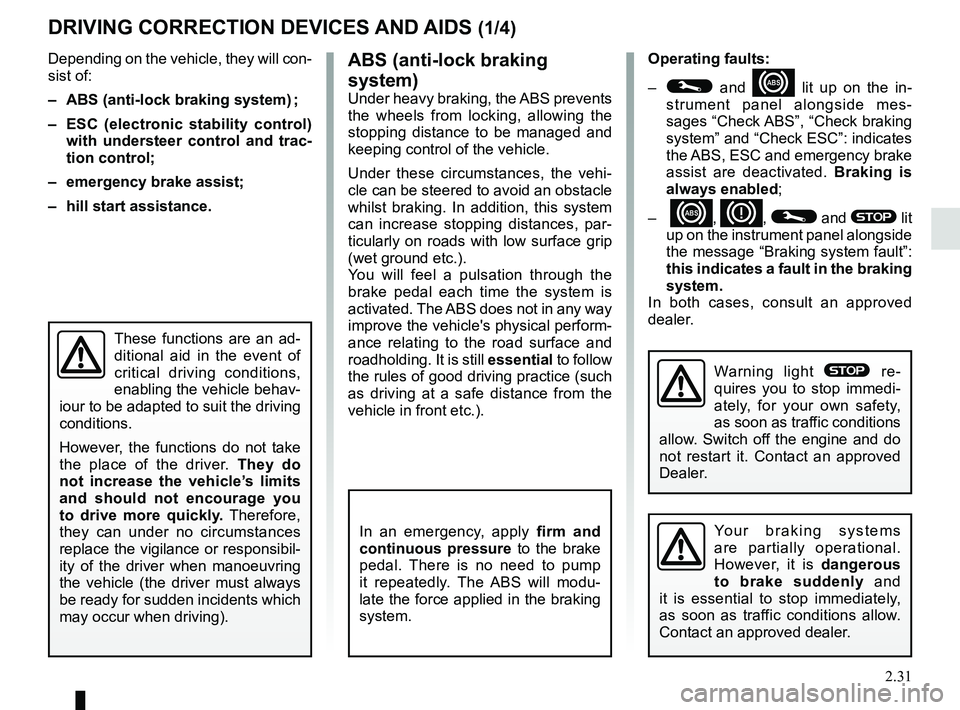
ABS (anti-lock braking
system)
Under heavy braking, the ABS prevents
the wheels from locking, allowing the
stopping distance to be managed and
keeping control of the vehicle.
Under these circumstances, the vehi-
cle can be steered to avoid an obstacle
whilst braking. In addition, this system
can increase stopping distances, par-
ticularly on roads with low surface grip
(wet ground etc.).
You will feel a pulsation through the
brake pedal each time the system is
activated. The ABS does not in any way
improve the vehicle's physical perform-
ance relating to the road surface and
roadholding. It is still essential to follow
the rules of good driving practice (such
as driving at a safe distance from the
vehicle in front etc.).
Depending on the vehicle, they will con-
sist of:
– ABS (anti-lock braking system) ;
– ESC
(electronic stability control)
with understeer control and trac-
tion control;
– emergency brake assist;
– hill start assistance.
In an emergency, apply firm and
continuous pressure to the brake
pedal. There is no need to pump
it repeatedly. The ABS will modu-
late the force applied in the braking
system.
These functions are an ad-
ditional aid in the event of
critical driving conditions,
enabling the vehicle behav-
iour to be adapted to suit the driving
conditions.
However, the functions do not take
the place of the driver. They do
not increase the vehicle’s limits
and should not encourage you
to drive more quickly. Therefore,
they can under no circumstances
replace the vigilance or responsibil-
ity of the driver when manoeuvring
the vehicle (the driver must always
be ready for sudden incidents which
may occur when driving).
Operating faults:
–
© and x lit up on the in-
strument panel alongside mes-
sages “Check ABS”, “Check braking
system” and “Check ESC”: indicates
the ABS, ESC and emergency brake
assist are deactivated. Braking is
always enabled;
–
x, D, © and ® lit
up on the instrument panel alongside
the message “Braking system fault”:
this indicates a fault in the braking
system.
In both cases, consult an approved
dealer.
Your braking systems
are partially operational.
However, it is dangerous
to brake suddenly and
it is essential to stop immediately,
as soon as traffic conditions allow.
Contact an approved dealer.
Warning light ® re-
quires you to stop immedi-
ately, for your own safety,
as soon as traffic conditions
allow. Switch off the engine and do
not restart it. Contact an approved
Dealer.
Page 136 of 332
2.32
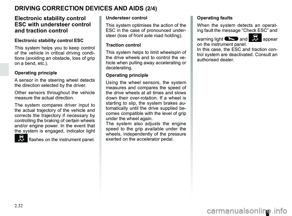
Electronic stability control
ESC with understeer control
and traction control
Electronic stability control ESC
This system helps you to keep control
of the vehicle in critical driving condi-
tions (avoiding an obstacle, loss of grip
on a bend, etc.).
Operating principle
A sensor in the steering wheel detects
the direction selected by the driver.
Other sensors throughout the vehicle
measure the actual direction.
The system compares driver input to
the actual trajectory of the vehicle and
corrects the trajectory if necessary by
controlling the braking of certain wheels
and/or engine power. In the event that
the system is engaged, indicator light
flashes on the instrument panel.Understeer control
This system optimises the action of the
ESC in the case of pronounced under-
steer (loss of front axle road holding).
Traction control
This system helps to limit wheelspin of
the drive wheels and to control the ve-
hicle when pulling away accelerating or
decelerating.
Operating principle
Using the wheel sensors, the system
measures and compares the speed of
the drive wheels at all times and slows
down their over-rotation. If a wheel is
starting to slip, the system brakes au-
tomatically until the drive supplied be-
comes compatible with the level of grip
under the wheel again.
The system also adjusts the engine
speed to the grip available under the
wheels, independently of the pressure
exerted on the accelerator pedal.
DRIVING CORRECTION DEVICES AND AIDS (2/4)
Operating faults
When the system detects an operat-
ing fault the message “Check ESC” and
warning light
© and appear
on the instrument panel.
In this case, the ESC and traction con-
trol system are deactivated. Consult an
authorised dealer.
Page 137 of 332
2.33
DRIVING CORRECTION DEVICES AND AIDS (3/4)
The traction control system offers ad-
ditional safety. It is recommended that
you do not drive with the function di-
sabled. Correct this as soon as pos-
sible by pressing the switch 1 again.
Note: The function is reactivated auto-
matically when the ignition is switched
on or when a speed of approximately
24 mph (40 km/h) is exceeded.
Emergency brake assistThis system supplements the ABS
and helps reduce vehicle stopping dis-
tances.
Operating principle
The system detects an emergency
braking situation. In this case, the brak-
ing assistance immediately develops
maximum power and may trigger ABS
regulation. ABS braking is maintained
as long as the brake pedal is not re-
leased.
Hazard warning lights illumination
Depending on the vehicle, these may
light up in the event of sudden decel-
eration.
These functions are an ad-
ditional aid in the event of
critical driving conditions,
enabling the vehicle behav-
iour to be adapted to suit the driving
conditions.
However, the functions do not take
the place of the driver. They do
not increase the vehicle’s limits
and should not encourage you
to drive more quickly. Therefore,
they can under no circumstances
replace the vigilance or responsibil-
ity of the driver when manoeuvring
the vehicle (the driver must always
be ready for sudden incidents which
may occur when driving).
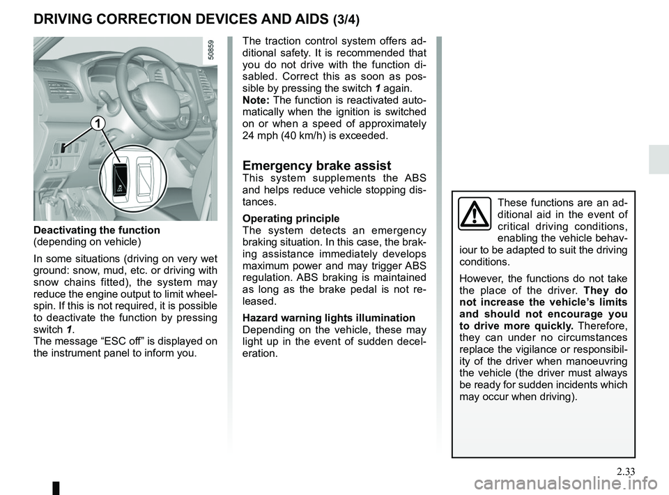
Deactivating the function
(depending on vehicle)
In some situations (driving on very wet
ground: snow, mud, etc. or driving with
snow chains fitted), the system may
reduce the engine output to limit wheel-
spin. If this is not required, it is possible
to deactivate the function by pressing
switch 1.
The message “ESC off” is displayed on
the instrument panel to inform you.
1
Page 138 of 332
2.34
DRIVING CORRECTION DEVICES AND AIDS (4/4)
Hill start assistance
Depending on the gradient of the in-
cline, this system assists the driver
when starting on a hill. It prevents the
vehicle from rolling backwards by au-
tomatically applying the brakes when
the driver lifts his/her foot off the brake
pedal to depress the accelerator pedal.
System operation
It only operates when the gear lever is
in a position other than neutral (other
than N or P for automatic transmis-
sions) and the vehicle is completely
stationary (brake pedal depressed)
The system holds the vehicle for ap-
proximately 2 seconds. The brakes are
then released (the vehicle will move ac-
cording to the slope).
The hill start assistance
system cannot completely
prevent the vehicle from
rolling backwards in all sit-
uations (extremely steep gradients,
etc.).
In all cases, the driver may depress
the brake pedal to prevent the vehi-
cle from rolling backwards.
The hill start assistance function
should not be used for prolonged
stops: use the brake pedal.
This function is not designed to im-
mobilise the vehicle permanently.
If necessary, use the brake pedal to
stop the vehicle.
The driver must remain particularly
vigilant when driving on slippery or
low-grip surfaces and/or on hills.
Risk of serious injury.
Page 139 of 332
2.35
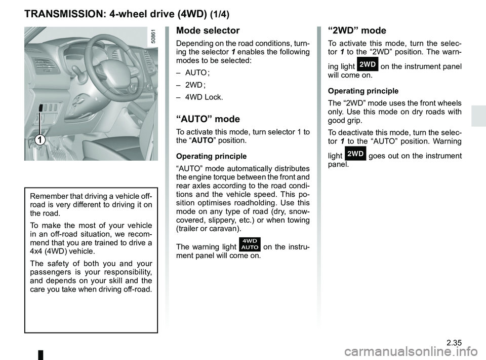
Mode selector
Depending on the road conditions, turn-
ing the selector 1 enables the following
modes to be selected:
– AUTO ;
– 2WD ;
– 4WD Lock.
“AUTO” mode
To activate this mode, turn selector 1 to
the “AUTO” position.
Operating principle
“AUTO” mode automatically distributes
the engine torque between the front and
rear axles according to the road condi-
tions and the vehicle speed. This po-
sition optimises roadholding. Use this
mode on any type of road (dry, snow-
covered, slippery, etc.) or when towing
(trailer or caravan).
The warning light
on the instru-
ment panel will come on.
TRANSMISSION: 4-wheel drive (4WD) (1/4)
“2WD” mode
To activate this mode, turn the selec-
tor 1 to the “2WD” position. The warn-
ing light
‘ on the instrument panel
will come on.
Operating principle
The “2WD” mode uses the front wheels
only. Use this mode on dry roads with
good grip.
To deactivate this mode, turn the selec-
tor 1 to the “AUTO” position. Warning
light
‘ goes out on the instrument
panel.
Remember that driving a vehicle off-
road is very different to driving it on
the road.
To make the most of your vehicle
in an off-road situation, we recom-
mend that you are trained to drive a
4x4 (4WD) vehicle.
The safety of both you and your
passengers is your responsibility,
and depends on your skill and the
care you take when driving off-road.
1
Page 140 of 332
2.36
TRANSMISSION: 4-wheel drive (4WD) (2/4)
This problem may be resolved by
changing the tyres. Always use four
identical tyres (same brand, profile,
etc.) and with similar wear.
In the event of excessive wheelspin, the
mechanical components may overheat.
If this happens:
– at first, the
’ warning light
comes on. “4WD Lock” mode is still
active – however, we recommend
that you stop as soon as possible to
allow the system to cool down (until
the warning light goes out);
– if the wheels still spin, the system au- tomatically switches to “2WD” mode
to protect the mechanical compo-
nents.
The message “4WD overheating” is
displayed on the instrument panel.
The mode cannot be changed while
the message is displayed.
Note: If the vehicle speed exceeds
approximately 24.8 mph (40 km/h) in
“4WD Lock” mode, the system auto-
matically switches back to “AUTO”
mode.
The
’ warning light goes out and
the
warning light comes on.
Special features of the
4-wheel drive transmission
The vehicle may make more noise when
the “AUTO” or “4WD Lock” modes are
activated. This is normal. If the system
detects a difference in the dimensions
of the front and rear wheels (eg. un-
derinflation, severe wear on an axle),
the system automatically switches to
“2WD” mode.
The message “4WD unavailable unsuit-
able tyres” is displayed on the instru-
ment panel. Drive as soon as possible
at a moderate speed to an approved
dealer.
“4WD Lock” mode
To activate this mode, turn selector 1 to
the “4WD Lock” position. The selector
the returns to the “AUTO” position. The
’ indicator light will light up on the
instrument panel.
Operating principle
“4WD Lock” mode distributes the
engine torque between the front and
rear axles in order to optimise the per-
formance capacity of the vehicle in off-
road situations. This mode should only
be used in extreme driving conditions
(mud, steep slopes, sand).
To deactivate this mode, turn selector 1
to the “4WD Lock” position again. The
warning light goes out on the instru-
ment panel.