ground RENAULT MASTER 2017 X62 / 2.G User Guide
[x] Cancel search | Manufacturer: RENAULT, Model Year: 2017, Model line: MASTER, Model: RENAULT MASTER 2017 X62 / 2.GPages: 286, PDF Size: 6.97 MB
Page 201 of 286
4.9
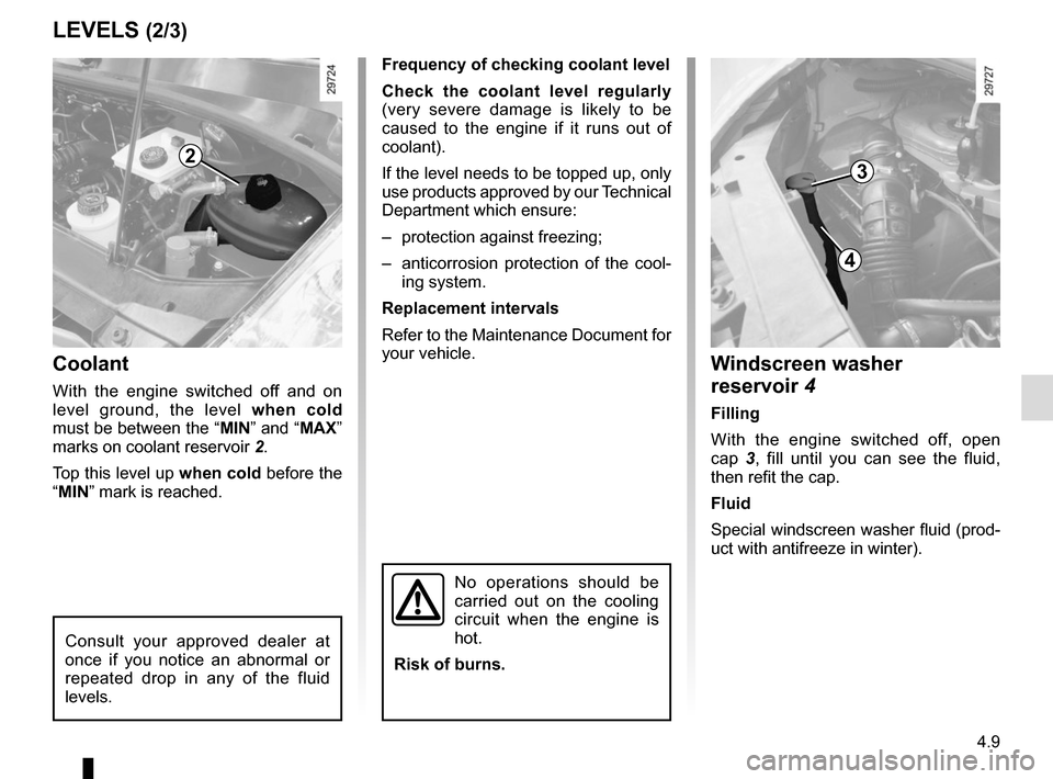
Coolant
With the engine switched off and on
level ground, the level when cold
must be between the “MIN” and “MAX”
marks on coolant reservoir 2.
Top this level up when cold before the
“MIN” mark is reached.
LEVELS (2/3)
Frequency of checking coolant level
Check the coolant level regularly
(very severe damage is likely to be
caused to the engine if it runs out of
coolant).
If the level needs to be topped up, only
use products approved by our Technical
Department which ensure:
– protection against freezing;
– anticorrosion protection of the cool- ing system.
Replacement intervals
Refer to the Maintenance Document for
your vehicle.
2
Windscreen washer
reservoir 4
Filling
With the engine switched off, open
cap 3, fill until you can see the fluid,
then refit the cap.
Fluid
Special windscreen washer fluid (prod-
uct with antifreeze in winter).
3
4
Consult your approved dealer at
once if you notice an abnormal or
repeated drop in any of the fluid
levels.
No operations should be
carried out on the cooling
circuit when the engine is
hot.
Risk of burns.
Page 202 of 286
4.10
Filters
The filter elements (air filter, diesel filter,
etc.) should be replaced during the
maintenance operations carried out on
your vehicle.
Replacement intervals for filter el-
ements: refer to the Maintenance
Document for your vehicle.
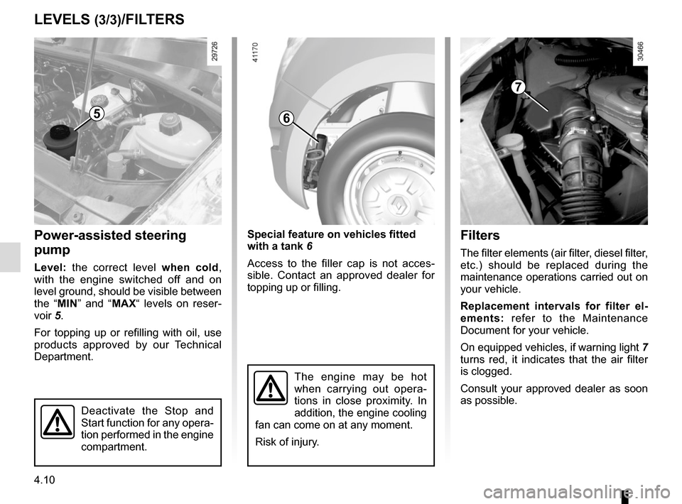
On equipped vehicles, if warning light 7
turns red, it indicates that the air filter
is clogged.
Consult your approved dealer as soon
as possible.
LEVELS (3/3)/FILTERS
Power-assisted steering
pump
Level: the correct level when cold,
with the engine switched off and on
level ground, should be visible between
the “MIN” and “MAX“ levels on reser-
voir 5.
For topping up or refilling with oil, use
products approved by our Technical
Department.
5
The engine may be hot
when carrying out opera-
tions in close proximity. In
addition, the engine cooling
fan can come on at any moment.
Risk of injury.
7
Deactivate the Stop and
Start function for any opera-
tion performed in the engine
compartment.
Special feature on vehicles fitted
with a tank 6
Access to the filler cap is not acces-
sible. Contact an approved dealer for
topping up or filling.
6
Page 213 of 286
5.3
PUNCTURE, EMERGENCY SPARE WHEEL (2/2)
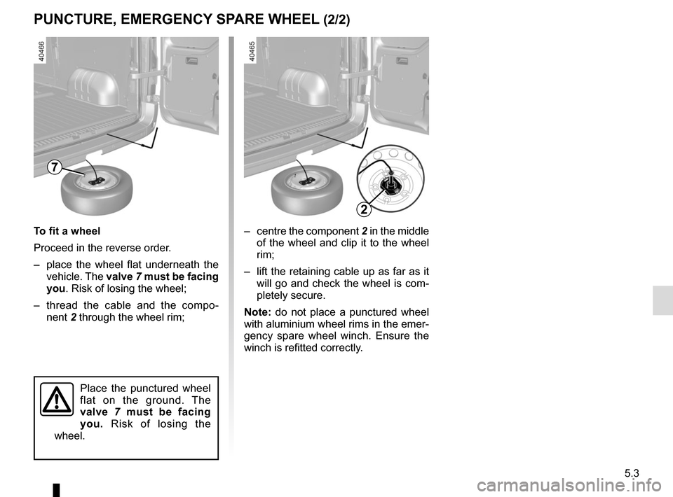
– centre the component 2 in the middle
of the wheel and clip it to the wheel
rim;
– lift the retaining cable up as far as it will go and check the wheel is com-
pletely secure.
Note: do not place a punctured wheel
with aluminium wheel rims in the emer-
gency spare wheel winch. Ensure the
winch is refitted correctly.
To fit a wheel
Proceed in the reverse order.
– place the wheel flat underneath the
vehicle. The valve 7 must be facing
you. Risk of losing the wheel;
– thread the cable and the compo- nent 2 through the wheel rim;
7
Place the punctured wheel
flat on the ground. The
valve 7 must be facing
you. Risk of losing the
wheel.
2
Page 224 of 286
5.14
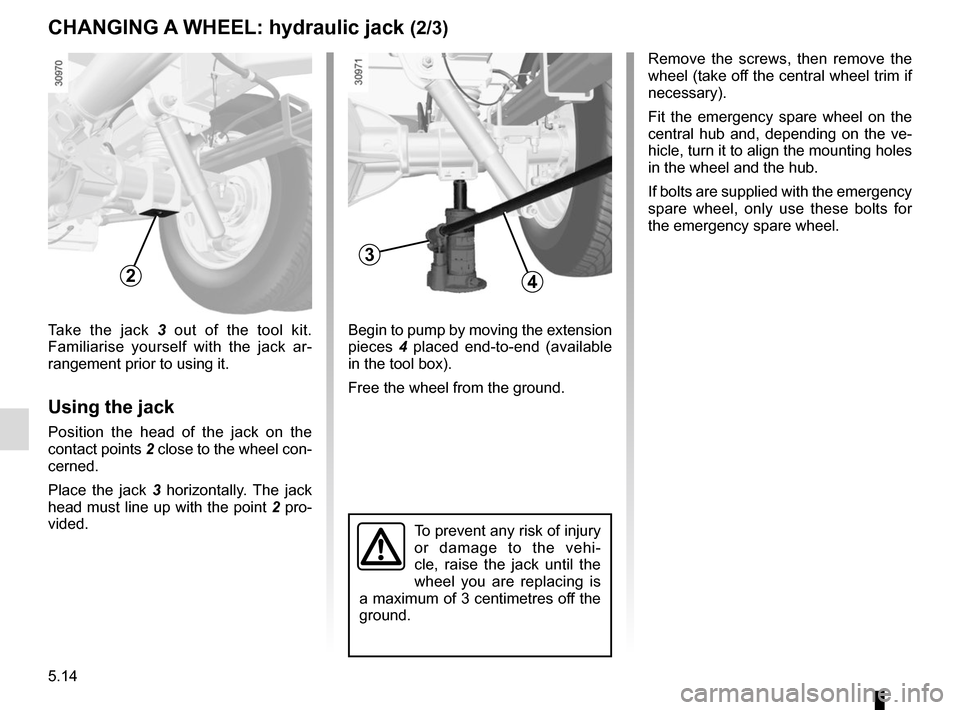
Begin to pump by moving the extension
pieces 4 placed end-to-end (available
in the tool box).
Free the wheel from the ground.Take the jack 3 out of the tool kit.
Familiarise yourself with the jack ar-
rangement prior to using it.
Using the jack
Position the head of the jack on the
contact points 2 close to the wheel con- cerned.
Place the jack 3 horizontally. The jack
head must line up with the point 2 pro-
vided.
3
CHANGING A WHEEL: hydraulic jack (2/3)
24
To prevent any risk of injury
or damage to the vehi-
cle, raise the jack until the
wheel you are replacing is
a maximum of 3 centimetres off the
ground.
Remove the screws, then remove the
wheel (take off the central wheel trim if
necessary).
Fit the emergency spare wheel on the
central hub and, depending on the ve-
hicle, turn it to align the mounting holes
in the wheel and the hub.
If bolts are supplied with the emergency
spare wheel, only use these bolts for
the emergency spare wheel.
Page 225 of 286
5.15
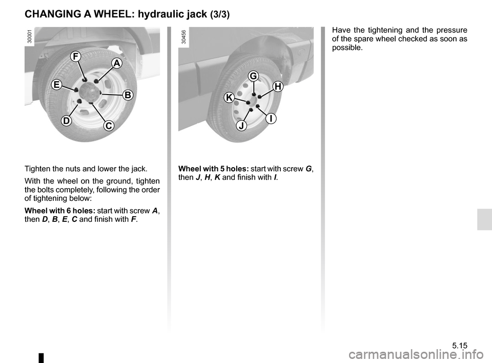
Tighten the nuts and lower the jack.
With the wheel on the ground, tighten
the bolts completely, following the order
of tightening below:
Wheel with 6 holes: start with screw A,
then D, B, E, C and finish with F.
A
B
CD
E
F
G
I
K
H
J
CHANGING A WHEEL: hydraulic jack (3/3)
Have the tightening and the pressure
of the spare wheel checked as soon as
possible.
Wheel with 5 holes: start with screw G,
then J, H, K and finish with I.
Page 226 of 286
5.16
CHANGING A WHEEL: jack (1/2)
2
If the vehicle is parked on
the hard shoulder, you must
warn other road users of
your vehicle’s presence
with a warning triangle or with other
devices as per the legislation ap-
plying to the country you are in.
Switch on the hazard war-
ning lights.
Keep the vehicle away from
traffic and on a level surface
where it will not slip.
Apply the parking brake and engage
a gear (first or reverse, or N for se-
quential gearboxes).
Ask all the passengers to leave the
vehicle and keep them away from
traffic.
To prevent any risk of injury
or damage to the vehi-
cle, raise the jack until the
wheel you are replacing is
a maximum of 3 centimetres off the
ground.
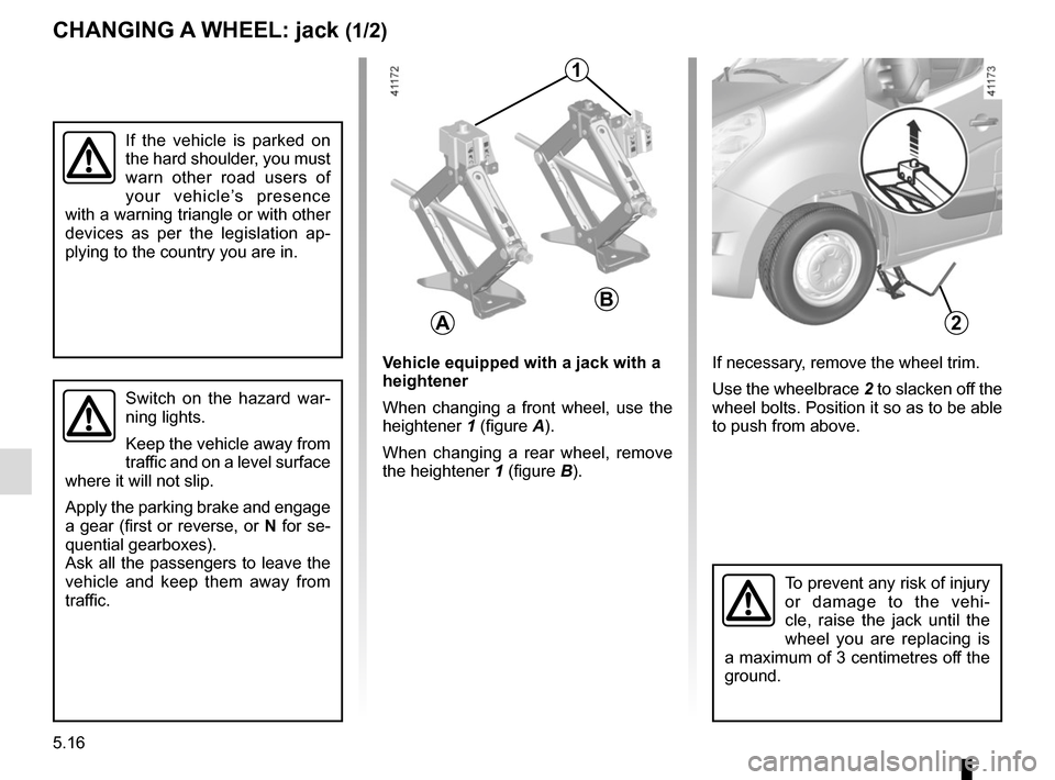
If necessary, remove the wheel trim.
Use the wheelbrace 2 to slacken off the
wheel bolts. Position it so as to be able
to push from above.Vehicle equipped with a jack with a
heightener
When changing a front wheel, use the
heightener 1 (figure A).
When changing a rear wheel, remove
the heightener 1 (figure B).
A
B
1
Page 227 of 286
5.17
CHANGING A WHEEL: jack (2/2)
If you have a puncture, re-
place the wheel as soon as
possible.
A tyre which has been
punctured should always be inspec-
ted (and repaired, where possible)
by a specialist.
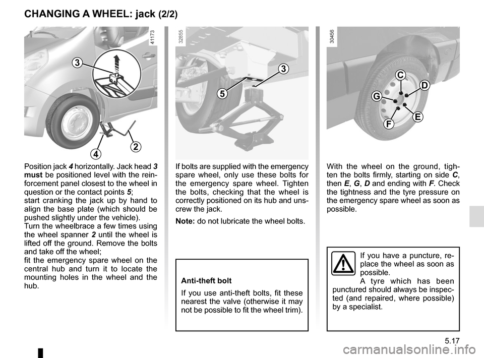
With the wheel on the ground, tigh-
ten the bolts firmly, starting on side C,
then E, G, D and ending with F. Check
the tightness and the tyre pressure on
the emergency spare wheel as soon as
possible.
C
E
G
D
F
If bolts are supplied with the emergency
spare wheel, only use these bolts for
the emergency spare wheel. Tighten
the bolts, checking that the wheel is
correctly positioned on its hub and uns-
crew the jack.
Note: do not lubricate the wheel bolts.
Anti-theft bolt
If you use anti-theft bolts, fit these
nearest the valve (otherwise it may
not be possible to fit the wheel trim).
Position jack 4 horizontally. Jack head 3
must be positioned level with the rein-
forcement panel closest to the wheel in
question or the contact points 5;
start cranking the jack up by hand to
align the base plate (which should be
pushed slightly under the vehicle).
Turn the wheelbrace a few times using
the wheel spanner 2 until the wheel is
lifted off the ground. Remove the bolts
and take off the wheel;
fit the emergency spare wheel on the
central hub and turn it to locate the
mounting holes in the wheel and the
hub.
3
5
3
24
Page 280 of 286
7.2
ALPHABETICAL INDEX (2/4)
emergency spare wheel ............................................. 5.2 – 5.3
enginetechnical specifications .................................................. 6.5
engine coolant ..................................................................... 4.9
engine oil ...................................................................4.4 → 4.7
engine oil level ..................................................1.81, 4.4 → 4.7
engine specifications ........................................................... 6.5
environment ............................................................\
........... 2.13
ESC: electronic stability control .............................2.16 → 2.20
external lights and signals .....................................1.95 → 1.99
external temperature ......................................................... 1.92
F
filter .................................................................\
................... 4.10
fitting a radio ...................................................................... 5.40
foot panel ........................................................................\
... 5.37
front passenger air bag deactivation .....................1.68 → 1.70
front seat adjustment ......................................................... 1.19
front seats ........................................................................\
.. 1.19
fuel advice on fuel economy ..................................... 2.8 → 2.11
consumption ...................................................... 2.8 → 2.11
filling .............................................................. 1.101 – 1.102
grade ..................................................................\
........ 1.101
fuel consumption ..................................................... 2.8 → 2.11
fuel filler cap ....................................................... 1.101 – 1.102
fuel grade........................................................................\
. 1.102
fuel level ........................................................................\
.... 1.81
fuel repriming ...................................................... 1.101 – 1.102
fuel tank .............................................................. 1.101 – 1.102
fuel tank capacity ............................................................. 1.101
fuses ..................................................................\
....5.28 → 5.32
G
gear lever......................................................2.14, 2.42 → 2.47
grab handle........................................................................\
3.18 grip control ........................................................................\
. 2.19
ground clearance ........................................................ 6.6 – 6.7
H
handbrake........................................................................\
.. 2.15
hazard warning lights signal ............................................ 1.100
headrest........................................................................\
..... 1.18
heated seats ...................................................................... 1.19
heating and air conditioning system ........3.2 – 3.3, 3.7 → 3.13
heating system ......................................3.2 → 3.6, 3.13 – 3.14
Hill Start Assist.......................................................2.16 → 2.20
hubcap tool ...................................................... 5.4, 5.11 – 5.12
I
idle speed ........................................................................\
.. 2.40
ignition switch ...................................................................... 2.2
indicators .............................................................\
............ 1.100
indicators: direction indicators ..................................................... 1.100
instrument panel ..............................................1.76 → 1.81
instrument panel ....................................................1.76 → 1.83
interior lighting: changing bulbs ............................................................. 5.27
interior trim maintenance ..................................................... 4.16 – 4.17
J
jack ...................................................................\
................... 5.4
K
keys ...................................................................\
........1.2 → 1.6
L
lane departure warning ..........................................2.24 → 2.26
levels: brake fluid ...................................................................... 4.8