sensor RENAULT SCENIC 2000 J64 / 1.G Technical Note 3426A User Guide
[x] Cancel search | Manufacturer: RENAULT, Model Year: 2000, Model line: SCENIC, Model: RENAULT SCENIC 2000 J64 / 1.GPages: 118, PDF Size: 1.5 MB
Page 60 of 118
Downloaded from www.Manualslib.com manuals search engine DIESEL EQUIPMENT
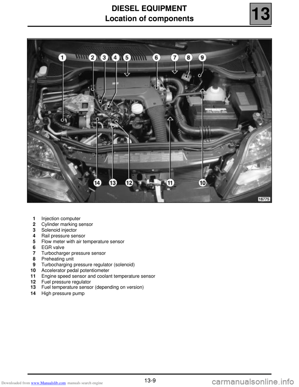
Location of components
13
13-9
Location of components
1
2
3
4
5
6
7
8
9
10
11
12
13
14Injection computer
Cylinder marking sensor
Solenoid injector
Rail pressure sensor
Flow meter with air temperature sensor
EGR valve
Turbocharger pressure sensor
Preheating unit
Turbocharging pressure regulator (solenoid)
Accelerator pedal potentiometer
Engine speed sensor and coolant temperature sensor
Fuel pressure regulator
Fuel temperature sensor (depending on version)
High pressure pump
Page 61 of 118
Downloaded from www.Manualslib.com manuals search engine DIESEL EQUIPMENT
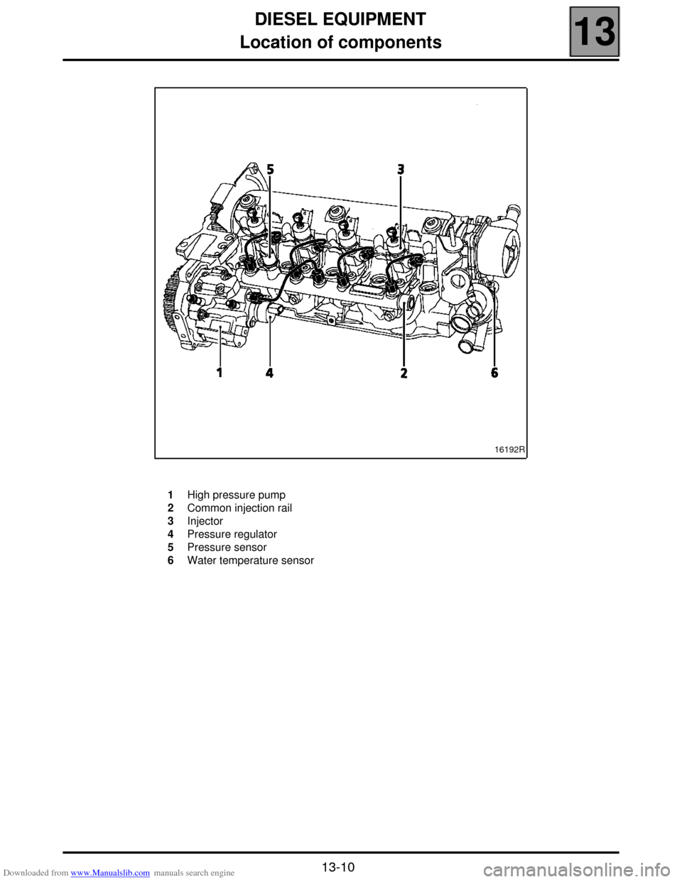
Location of components
13
13-10
16192R
1
2
3
4
5
6High pressure pump
Common injection rail
Injector
Pressure regulator
Pressure sensor
Water temperature sensor
Page 62 of 118
Downloaded from www.Manualslib.com manuals search engine DIESEL EQUIPMENT
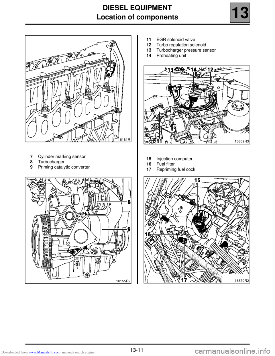
Location of components
13
13-11
16181R
7
8
9Cylinder marking sensor
Turbocharger
Priming catalytic converter
16155R2
11
12
13
14EGR solenoid valve
Turbo regulation solenoid
Turbocharger pressure sensor
Preheating unit
16869R3
15
16
17Injection computer
Fuel filter
Repriming fuel cock
16870R2
Page 63 of 118

Downloaded from www.Manualslib.com manuals search engine DIESEL EQUIPMENT
Injection warning light
13
13-12
Injection warning light
Vehicles using the high pressure diesel system are fitted with two injection warning lights used during the preheating
phase and in case of an injection fault (or engine overheating).
WARNING LIGHT PRINCIPLE
!When ignition is switched on, the preheating light is lit during the preheating phase and then goes out (see section
13 "Pre-postheating control").
!When there is a fault on the injection system the "fault" warning light lights up. These faults are:
– internal computer fault,
– engine speed fault (the vehicle doesn't start),
– main relay or low pressure fault (the vehicle doesn't start),
– injector fault,
–TDC sensor coherence fault and camshaft sensor,
– rail pressure sensor fault,
– rail pressure regulator fault,
– accelerator potentiometer fault,
– engine immobiliser fault,
– computer supply voltage fault,
– engine overheating.
NOTE: the OBD warning light (symbolised by an engine), visible when the ignition is switched on, is never visible
when the engine is running.
Page 79 of 118
Downloaded from www.Manualslib.com manuals search engine DIESEL EQUIPMENT
Injector rail
13
13-28
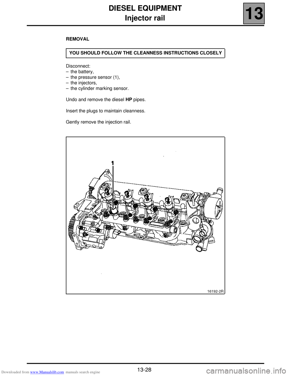
REMOVAL
Disconnect:
– the battery,
– the pressure sensor (1),
– the injectors,
– the cylinder marking sensor.
Undo and remove the diesel HP pipes.
Insert the plugs to maintain cleanness.
Gently remove the injection rail.YOU SHOULD FOLLOW THE CLEANNESS INSTRUCTIONS CLOSELY
16192-2R
Page 89 of 118
Downloaded from www.Manualslib.com manuals search engine DIESEL EQUIPMENT
Pressure sensor
13
13-38
Pressure sensor
TIGHTENING TORQUES (In daN.m or/and°)
Pressure sensor 3.5 ± 0.5
IMPORTANT: before any intervention, connect
the after-sales diagnostic tool, query the injection
computer and check that the injection rail is not
under pressure. Take note of the fuel temperature.
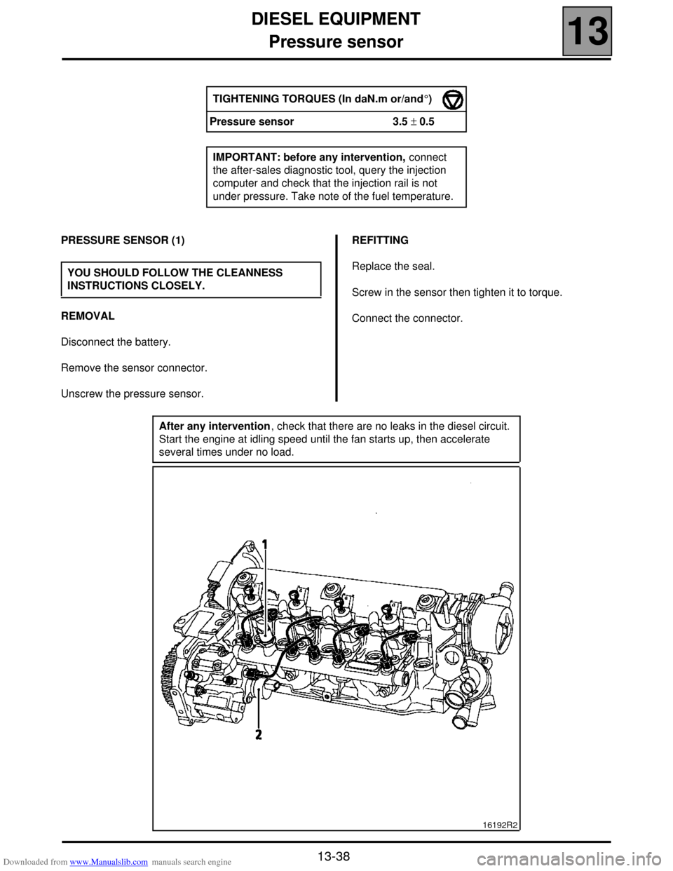
PRESSURE SENSOR (1)
REMOVAL
Disconnect the battery.
Remove the sensor connector.
Unscrew the pressure sensor.REFITTING
Replace the seal.
Screw in the sensor then tighten it to torque.
Connect the connector. YOU SHOULD FOLLOW THE CLEANNESS
INSTRUCTIONS CLOSELY.
After any intervention, check that there are no leaks in the diesel circuit.
Start the engine at idling speed until the fan starts up, then accelerate
several times under no load.
16192R2
Page 90 of 118
Downloaded from www.Manualslib.com manuals search engine DIESEL EQUIPMENT
Pressure regulator
13
13-39
Pressure regulator
TIGHTENING TORQUES (In daN.m or/and °)
Regulator bolt 0.9 ± 0.1
IMPORTANT: before any intervention, connect
the after-sales diagnostic tool, query the injection
computer and check that the injection rail is not
under pressure. Take note of the fuel temperature.
PRESSURE REGULATOR (2)
REMOVAL
Disconnect the battery.
Remove the regulator connector.
Remove the retaining bracket for the diesel
temperature sensor.
Unscrew the regulator mounting bolts.
Remove the regulator by turning in an anticlockwise
direction (do not use any tools as a lever when
removing the pump regulator).REFITTING
Change the seals.
Dampen the seals with clean diesel.
Replace the regulator in the pump by turning it in an
anticlockwise direction (do not use any tools as a lever
when replacing the pump regulator).
Fit the mounting bolts then tighten to torque.
Connect the connector. YOU SHOULD FOLLOW THE CLEANNESS
INSTRUCTIONS CLOSELY.
After any intervention, check that there are no leaks in the diesel circuit.
Start the engine at idling speed until the fan starts up, then accelerate
several times under no load.
Page 92 of 118
Downloaded from www.Manualslib.com manuals search engine DIESEL EQUIPMENT
Coolant temperature management
13
13-41
Coolant temperature management
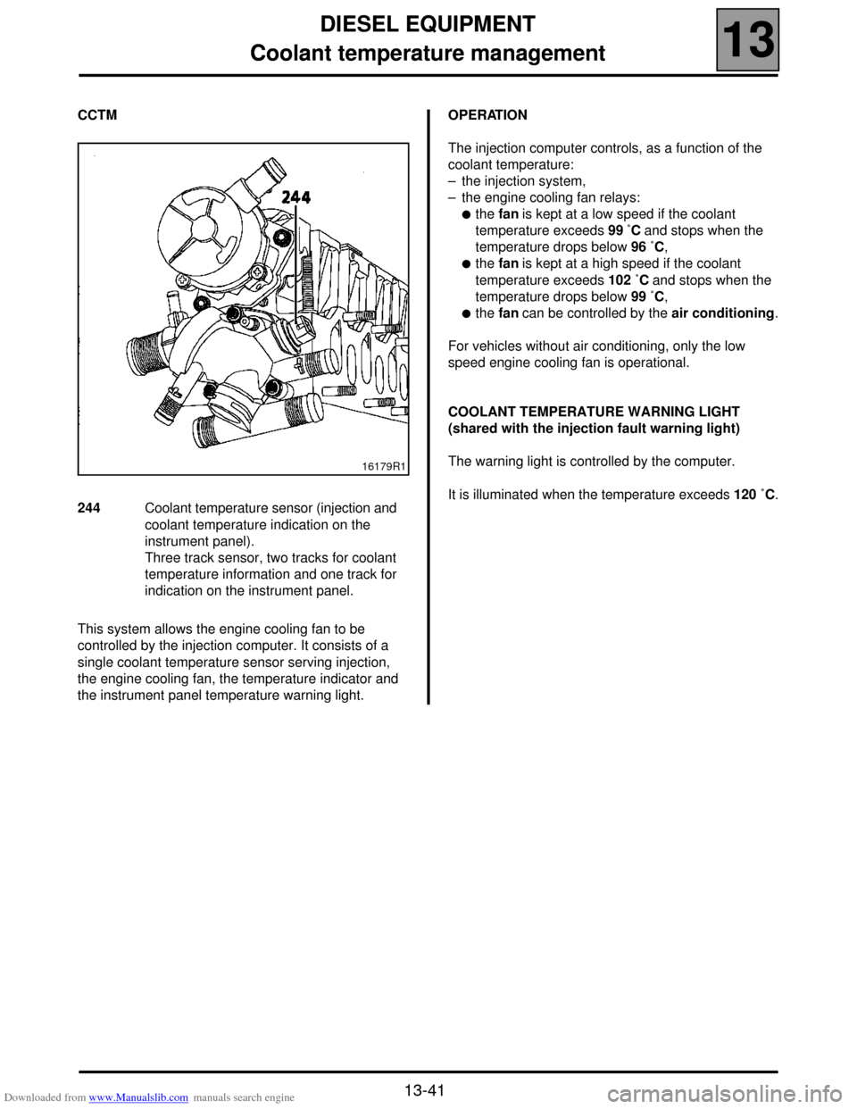
CCTM
This system allows the engine cooling fan to be
controlled by the injection computer. It consists of a
single coolant temperature sensor serving injection,
the engine cooling fan, the temperature indicator and
the instrument panel temperature warning light.OPERATION
The injection computer controls, as a function of the
coolant temperature:
– the injection system,
– the engine cooling fan relays:
!the fan is kept at a low speed if the coolant
temperature exceeds 99 ˚C and stops when the
temperature drops below 96 ˚C,
!the fan is kept at a high speed if the coolant
temperature exceeds 102 ˚C and stops when the
temperature drops below 99 ˚C,
!the fan can be controlled by the air conditioning.
For vehicles without air conditioning, only the low
speed engine cooling fan is operational.
COOLANT TEMPERATURE WARNING LIGHT
(shared with the injection fault warning light)
The warning light is controlled by the computer.
It is illuminated when the temperature exceeds 120 ˚C.
16179R1
244 Coolant temperature sensor (injection and
coolant temperature indication on the
instrument panel).
Three track sensor, two tracks for coolant
temperature information and one track for
indication on the instrument panel.
Page 93 of 118
Downloaded from www.Manualslib.com manuals search engine DIESEL EQUIPMENT
Computer
13
13-42
Computer
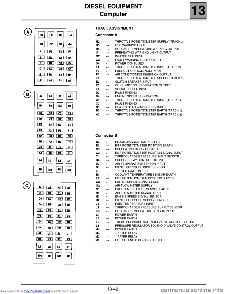
TRACK ASSIGNMENT
Connector A
H2
H3
H4
G1
G2
G3
G4
F1
F3
F4
E1
E2
E3
E4
D3
D4
C1
C3
B1
B3
A3---
→
→
→
←
→
←
←
←
→
---
←
→
←
→←
→
←
→←
→
---
---THROTTLE POTENTIOMETER SUPPLY (TRACK 2)
OBD WARNING LIGHT
COOLANT TEMPERATURE WARNING OUTPUT
PREHEATING WARNING LIGHT OUTPUT
IMMOBILISER INPUT
FAULT WARNING LIGHT OUTPUT
POWER CONSUMED
THROTTLE POTENTIOMETER INPUT (TRACK 2)
FUEL CUT-OFF SOLENOID INPUT
AIR CONDITIONING INHIBITION OUTPUT
THROTTLE POTENTIOMETER SUPPLY (TRACK 1)
CLUTCH BREAKER INPUT
CONSUMPTION INFORMATION OUTPUT
VEHICLE SPEED INPUT
FAULT FINDING
ENGINE SPEED INFORMATION
THROTTLE POTENTIOMETER INPUT (TRACK 1)
FAULT FINDING
HEATED REAR WINDSCREEN INPUT
THROTTLE POTENTIOMETER EARTH (TRACK 1)
THROTTLE POTENTIOMETER EARTH (TRACK 2)
Connector B
B3
B2
C3
C2
C1
D4
D3
D1
E3
E1
F2
G3
G2
G1
H4
H3
H2
J3
J2
K3
L4
L3
L2
L1
M4
M3
M2
M1←
---
→
←
←
→
←
←
---
---
---
←
---
---
←
←
---
←
---
←
---
---
→
→
---
---
---
→PLUGS DIAGNOSTICS INPUT (1)
EGR POTENTIOMETER POSITION EARTH
PREHEATING RELAY CONTROL
EGR POTENTIOMETER POSITION SIGNAL INPUT
TURBOCHARGER PRESSURE INPUT SENSOR
SUPPLY RELAY CONTROL OUTPUT
AIR TEMPERATURE SENSOR INPUT
DIESEL PRESSURE INPUT SENSOR
+ AFTER IGNITION FEED
COOLANT TEMPERATURE SENSOR EARTH
EGR POTENTIOMETER POSITION SUPPLY
ENGINE SPEED SIGNAL SENSOR
AIR FLOW METER SUPPLY
FUEL TEMPERATURE SENSOR EARTH
AIR FLOW METER SIGNAL INPUT
ENGINE SPEED SIGNAL SENSOR
DIESEL PRESSURE SUPPLY SENSOR
FUEL TEMPERATURE INPUT
TURBOCHARGER PRESSURE SUPPLY SENSOR
COOLANT TEMPERATURE SENSOR INPUT
POWER EARTH
POWER EARTH
TURBO PRESSURE SOLENOID VALVE CONTROL OUTPUT
PRESSURE REGULATOR SOLENOID VALVE CONTROL OUTPUT
POWER EARTH
+ AFTER RELAY
+ AFTER RELAY
EGR SOLENOID CONTROL OUTPUT
Page 94 of 118
Downloaded from www.Manualslib.com manuals search engine DIESEL EQUIPMENT
Computer
13
13-43
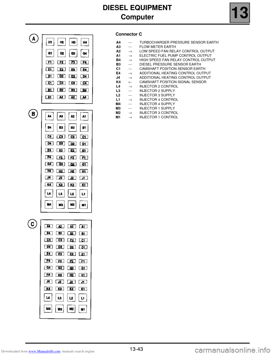
Connector C
A4
A3
A2
A1
B4
B3
C1
E4
J4
K4
L4
L3
L2
L1
M4
M3
M2
M1---
---
→
→
→
---
---
→
→
←
→
---
---
→
---
---
→
→TURBOCHARGER PRESSURE SENSOR EARTH
FLOW METER EARTH
LOW SPEED FAN RELAY CONTROL OUTPUT
ELECTRIC FUEL PUMP CONTROL OUTPUT
HIGH SPEED FAN RELAY CONTROL OUTPUT
DIESEL PRESSURE SENSOR EARTH
CAMSHAFT POSITION SENSOR EARTH
ADDITIONAL HEATING CONTROL OUTPUT
ADDITIONAL HEATING CONTROL OUTPUT
CAMSHAFT POSITION SIGNAL SENSOR
INJECTOR 2 CONTROL
INJECTOR 2 SUPPLY
INJECTOR 3 SUPPLY
INJECTOR 4 CONTROL
INJECTOR 4 SUPPLY
INJECTOR 1 SUPPLY
INJECTOR 3 CONTROL
INJECTOR 1 CONTROL