sensor RENAULT SCENIC 2000 J64 / 1.G Technical Note 3426A Workshop Manual
[x] Cancel search | Manufacturer: RENAULT, Model Year: 2000, Model line: SCENIC, Model: RENAULT SCENIC 2000 J64 / 1.GPages: 118, PDF Size: 1.5 MB
Page 2 of 118
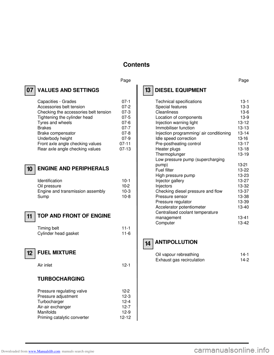
Downloaded from www.Manualslib.com manuals search engine Contents
Page
07
10
11
12
VALUES AND SETTINGS
Capacities - Grades 07-1
Accessories belt tension 07-2
Checking the accessories belt tension 07-3
Tightening the cylinder head 07-5
Tyres and wheels 07-6
Brakes 07-7
Brake compensator 07-8
Underbody height 07-9
Front axle angle checking values 07-11
Rear axle angle checking values 07-13
ENGINE AND PERIPHERALS
Identification 10-1
Oil pressure 10-2
Engine and transmission assembly 10-3
Sump 10-8
TOP AND FRONT OF ENGINE
Timing belt 11-1
Cylinder head gasket 11-6
FUEL MIXTURE
Air inlet 12-1
TURBOCHARGING
Pressure regulating valve 12-2
Pressure adjustment 12-3
Turbocharger 12-4
Air-air exchanger 12-7
Manifolds 12-9
Priming catalytic converter 12-12Page
13
14
DIESEL EQUIPMENT
Technical specifications 13-1
Special features 13-3
Cleanliness 13-6
Location of components 13-9
Injection warning light 13-12
Immobiliser function 13-13
Injection programming/ air conditioning 13-14
Idle speed correction13-16
Pre-postheating control 13-17
Heater plugs 13-18
Thermoplunger 13-19
Low pressure pump (supercharging
pump)13-21
Fuel filter 13-22
High pressure pump 13-23
Injector gallery 13-27
Injectors 13-32
Checking diesel pressure and flow 13-37
Pressure sensor 13-38
Pressure regulator 13-39
Accelerator potentiometer 13-40
Centralised coolant temperature
management 13-41
Computer 13-42
ANTIPOLLUTION
Oil vapour rebreathing 14-1
Exhaust gas recirculation 14-2
Page 20 of 118
Downloaded from www.Manualslib.com manuals search engine ENGINE AND PERIPHERALS
Engine and transmission assembly
10
10-4
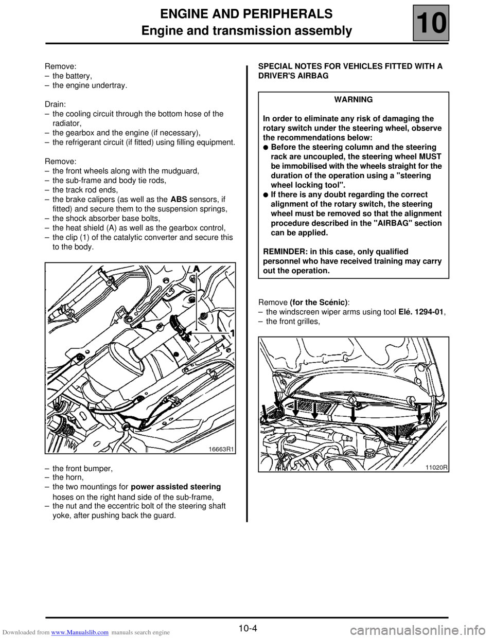
Remove:
– the battery,
– the engine undertray.
Drain:
– the cooling circuit through the bottom hose of the
radiator,
– the gearbox and the engine (if necessary),
– the refrigerant circuit (if fitted) using filling equipment.
Remove:
– the front wheels along with the mudguard,
– the sub-frame and body tie rods,
– the track rod ends,
– the brake calipers (as well as the ABS sensors, if
fitted) and secure them to the suspension springs,
– the shock absorber base bolts,
– the heat shield (A) as well as the gearbox control,
– the clip (1) of the catalytic converter and secure this
to the body.
– the front bumper,
– the horn,
– the two mountings for power assisted steering
hoses on the right hand side of the sub-frame,
– the nut and the eccentric bolt of the steering shaft
yoke, after pushing back the guard.SPECIAL NOTES FOR VEHICLES FITTED WITH A
DRIVER'S AIRBAG
Remove (for the Scénic):
– the windscreen wiper arms using tool Elé. 1294-01,
– the front grilles,
16663R1
WARNING
In order to eliminate any risk of damaging the
rotary switch under the steering wheel, observe
the recommendations below:
!Before the steering column and the steering
rack are uncoupled, the steering wheel MUST
be immobilised with the wheels straight for the
duration of the operation using a "steering
wheel locking tool".
!If there is any doubt regarding the correct
alignment of the rotary switch, the steering
wheel must be removed so that the alignment
procedure described in the "AIRBAG" section
can be applied.
REMINDER: in this case, only qualified
personnel who have received training may carry
out the operation.
11020R
Page 35 of 118
Downloaded from www.Manualslib.com manuals search engine TOP AND FRONT OF ENGINE
Cylinder head gasket
11
11 - 9
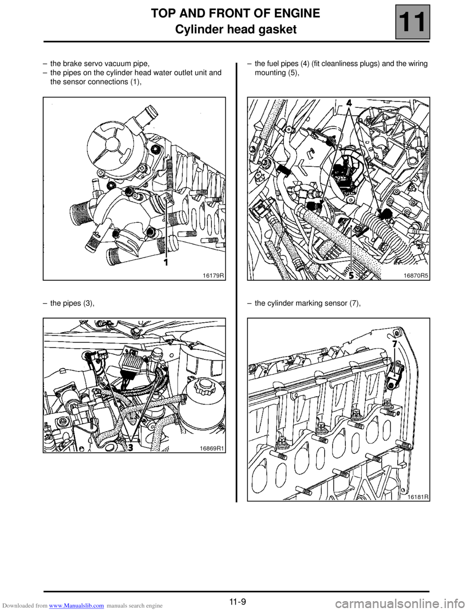
– the brake servo vacuum pipe,
– the pipes on the cylinder head water outlet unit and
the sensor connections (1),
– the pipes (3),– the fuel pipes (4) (fit cleanliness plugs) and the wiring
mounting (5),
– the cylinder marking sensor (7),
16179R
16869R116870R5
16181R
Page 44 of 118
Downloaded from www.Manualslib.com manuals search engine TURBOCHARGING
Turbocharger
12
12-6
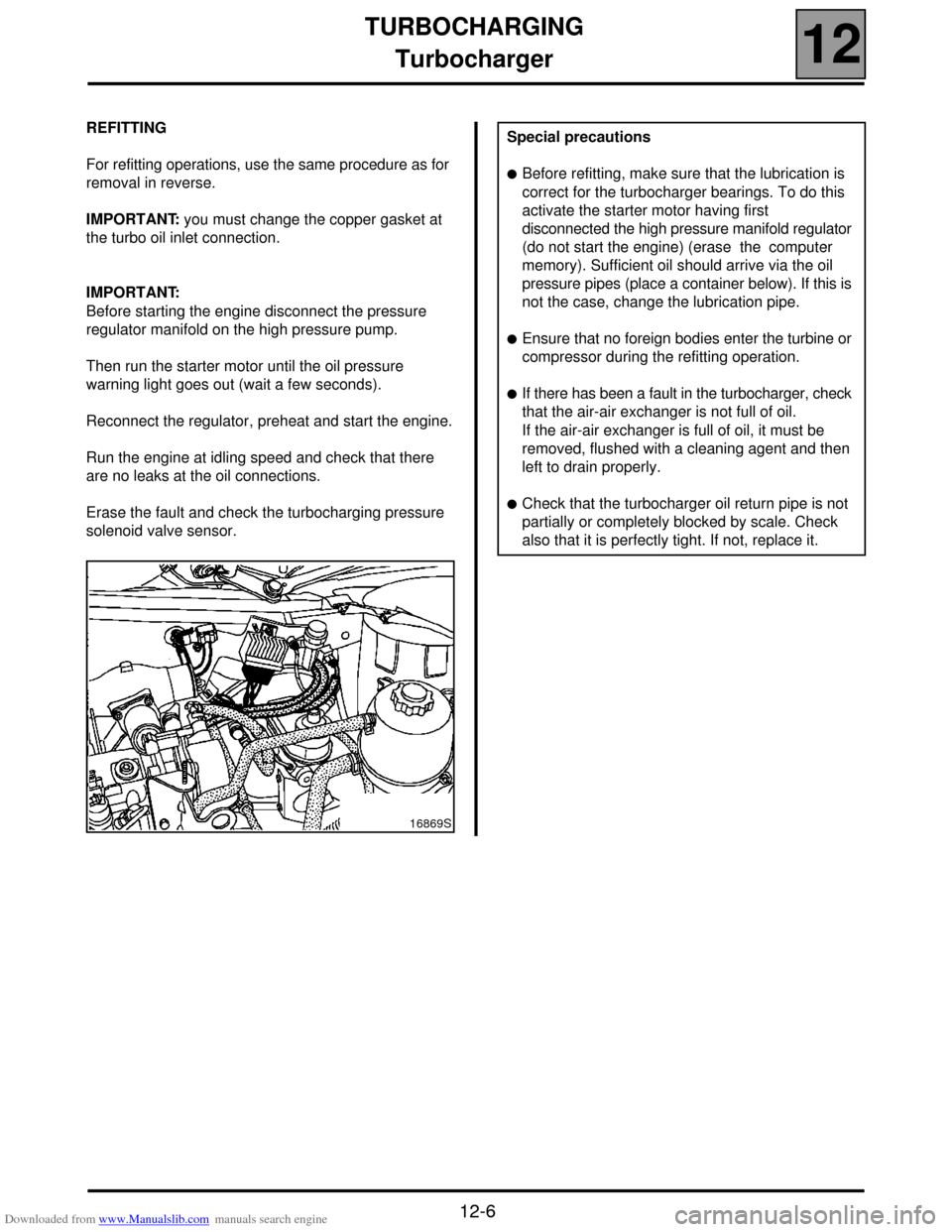
REFITTING
For refitting operations, use the same procedure as for
removal in reverse.
IMPORTANT: you must change the copper gasket at
the turbo oil inlet connection.
IMPORTANT:
Before starting the engine disconnect the pressure
regulator manifold on the high pressure pump.
Then run the starter motor until the oil pressure
warning light goes out (wait a few seconds).
Reconnect the regulator, preheat and start the engine.
Run the engine at idling speed and check that there
are no leaks at the oil connections.
Erase the fault and check the turbocharging pressure
solenoid valve sensor.
16869S
Special precautions
!Before refitting, make sure that the lubrication is
correct for the turbocharger bearings. To do this
activate the starter motor having first
disconnected the high pressure manifold regulator
(do not start the engine) (erase the computer
memory). Sufficient oil should arrive via the oil
pressure pipes (place a container below). If this is
not the case, change the lubrication pipe.
!Ensure that no foreign bodies enter the turbine or
compressor during the refitting operation.
!If there has been a fault in the turbocharger, check
that the air-air exchanger is not full of oil.
If the air-air exchanger is full of oil, it must be
removed, flushed with a cleaning agent and then
left to drain properly.
!Check that the turbocharger oil return pipe is not
partially or completely blocked by scale. Check
also that it is perfectly tight. If not, replace it.
Page 47 of 118
Downloaded from www.Manualslib.com manuals search engine FUEL MIXTURE
Manifolds
12
12-9
FUEL MIXTURE
Manifolds
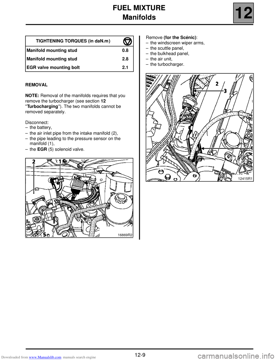
REMOVAL
NOTE: Removal of the manifolds requires that you
remove the turbocharger (see section 12
"Turbocharging"). The two manifolds cannot be
removed separately.
Disconnect:
– the battery,
– the air inlet pipe from the intake manifold (2),
– the pipe leading to the pressure sensor on the
manifold (1),
– the EGR (5) solenoid valve.Remove (for the Scénic):
– the windscreen wiper arms,
– the scuttle panel,
– the bulkhead panel,
– the air unit,
– the turbocharger. TIGHTENING TORQUES (in daN.m )
Manifold mounting stud 0.8
Manifold mounting stud 2.8
EGR valve mounting bolt 2.1
16869R2
12415R1
Page 52 of 118

Downloaded from www.Manualslib.com manuals search engine DIESEL EQUIPMENT
Specifications
13
113
DIESEL EQUIPMENT
Specifications
Vehicle GearboxEngine
Depollution
standard
Type IndexBore
(mm) Stroke
(mm) Cubic
capacity
(cm
3)Compres-
sion ratioCatalytic
converter
XA05 JC5 F9Q 732 80 93 1 870 19/1◊ C103 Euro 2000
ENGINE SPEED (rpm) SMOKE DENSITY
IDLING SPEED Max. - no loadMax. - under
loadHomologation value Max. - Max
835 ± 50 4,700 ± 150 4,500 ± 100
1.5 m
-1 (46 %) 3 m-1 (70 %)
DESCRIPTION BRAND/TYPE SPECIAL NOTES
High pressure pumpBOSCH
CR/CP153/R65/10-15Pressure from 250 to 1350 bars
Supercharging pump (low
pressure)BOSCHPressure from 2.5 to 4 bars
Flow: 80 to 100 litres/hour minimum
Diesel pressure sensor BOSCHFitted to the injection rail
Resistance: tracks 1,2 and 1,3 = 4.3 MΩ
tracks 2,3 = 1050 Ω
Injectors BOSCHSolenoid injector
Resistance: < 2 Ω
Maximum pressure 1525 bars
Pressure regulator - Integrated with the high pressure pump
Resistance: ≈ 5 Ω at 20˚ C
Injection computer BOSCH128 track computer
Pre-postheating unit NAGARES BED/7With pre-postheating function controlled by the
injection computer
Heater plugsBERU
or
CHAMPIONResistance: 0.6 Ω connector removed
Accelerator potentiometer CTSDouble track potentiometer
Track resistance ≈ 1.7 Ω
Air intake temperature sensor SIEMENSintegrated in the flow meter
Resistance between 100 Ω and 40 Ω
13-1
Page 53 of 118
Downloaded from www.Manualslib.com manuals search engine DIESEL EQUIPMENT
Specifications
13
13-2
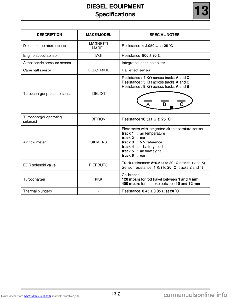
DESCRIPTION MAKE/MODEL SPECIAL NOTES
Diesel temperature sensorMAGNETTI
MARELIResistance: ≈ 2.050 Ω at 25 ˚C
Engine speed sensor MGI Resistance: 800 ± 80 Ω
Atmospheric pressure sensor - Integrated in the computer
Camshaft sensor ELECTRIFIL Hall effect sensor
Turbocharger pressure sensor DELCOResistance : 4 KΩ across tracks A and C
Resistance : 5 KΩ across tracks A and C
Resistance : 9 KΩ across tracks A and B
Turbocharger operating
solenoidBITRON Resistance 16.5±1 Ω at 25 ˚C
Air flow meter SIEMENSFlow meter with integrated air temperature sensor
track 1 : air temperature
track 2 : earth
track 3 : 5 V reference
track 4 : + battery feed
track 5 : air flow signal
track 6 : earth
EGR solenoid valve PIERBURGTrack resistance: 8±0.5 Ω to 20 ˚C (tracks 1 and 5)
Sensor resistance: 4 KΩ to 20 ˚C (tracks 2 and 4)
Turbocharger KKKCalibration :
120 mbars for rod travel between 1 and 4 mm
400 mbars for a stroke between 10 and 12 mm
Thermal plungers - Resistance: 0.45 ± 0.05 Ω at 20 ˚C
Page 54 of 118
Downloaded from www.Manualslib.com manuals search engine DIESEL EQUIPMENT
Special notes
13
13-3
Special notes
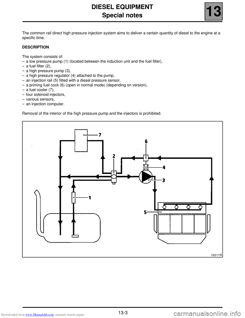
The common rail direct high pressure injection system aims to deliver a certain quantity of diesel to the engine at a
specific time.
DESCRIPTION
The system consists of:
– a low pressure pump (1) (located between the induction unit and the fuel filter),
– a fuel filter (2),
– a high pressure pump (3),
– a high pressure regulator (4) attached to the pump,
– an injection rail (5) fitted with a diesel pressure sensor,
– a priming fuel cock (6) (open in normal mode) (depending on version),
– a fuel cooler (7),
– four solenoid injectors,
– various sensors,
– an injection computer.
Removal of the interior of the high pressure pump and the injectors is prohibited.
16311R
Page 55 of 118

Downloaded from www.Manualslib.com manuals search engine DIESEL EQUIPMENT
Special notes
13
13-4
OPERATION
The common rail direct high pressure injection system is a sequential diesel injection system (based on the
operation of multipoint injection for petrol engines).
This new injection system reduces operating noise, lowers the quantity of polluting gas and particles and produces
significant engine torque at low engine speeds thanks to a pre-injection procedure.
The low pressure pump (also called the supercharging pump) supplies the HP pump, through the filter with pressure
of between 2.5 and 4 bars.
The HP pump generates the high pressure sent to the injection rail. The pressure regulator located on the pump
modulates the value of the high pressure via the computer. The rail supplies each injector through a steel pipe.
The computer:
– determines the value of injection pressure necessary for the engine to operate well and then controls the pressure
regulator. It checks that the pressure value is correct by analysing the value transmitted by the pressure sensor
located on the rail,
– determines the injection time necessary to deliver the right quantity of diesel and the moment when injection should
be started,
– controls each injector electrically and individually after determining these two values.
The injected flow to the engine is determined depending on:
– the duration of injector control,
– the injector opening and closing speed,
– the needle stroke (determined by the type of injector),
– the nominal injector hydraulic flow (determined by the type of injector),
– the high pressure rail pressure controlled by the computer.
FOR ANY INTERVENTION IN THE HIGH PRESSURE INJECTION SYSTEM YOU MUST RESPECT THE
CLEANING AND SAFETY ADVICE SPECIFIED IN THIS DOCUMENT.
Page 56 of 118
Downloaded from www.Manualslib.com manuals search engine DIESEL EQUIPMENT
Special notes
13
13-5
POST-REPAIR CHECK
A fuel cock is fitted to the fuel filter at the level of the diesel return pipe leading to the tank. It should be in open
position for normal operation.
However, to carry out a circuit reignition after an intervention, a filter change or a fuel fault, you should:
– close the fuel cock,
– start the low pressure pump by switching on the ignition several times,
– start the engine,
– OPEN THE FUEL COCK (the valve is open when the two coloured lines are aligned).
NOTE: certain vehicles are not fitted with a fuel cock. In this case, ignore this operation.
IMPORTANT: the engine must not run with diesel containing more than 10 % diester.
The system can inject the diesel into the engine up to a pressure of 1350 bars. Before any intervention, check
that the injector rail is depressurised.
It is absolutely vital that you observe the tightening torque:
– of the high pressure pipes,
– of the injector on the cylinder head,
– of the pressure regulator,
– of the pressure sensor.
When the high pressure pump, injectors, supply, return and high pressure output unions are repaired or
removed, the bores should be fitted with new and appropriate core seals to avoid impurities.
When replacing a high pressure pipe, the following procedure should be observed:
– remove the high pressure pipe,
– fit the cleanliness plugs,
– loosen the high pressure rail and the pump/rail pipe,
– fit the high pressure pipe,
– tighten the injector side union to torque,
– tighten the connection on the high pressure pump side to torque,
– tighten the high pressure rail fastenings to torque.
– tighten the pump/rail pipe to torque (pump side first).
It is prohibited to remove the interior of the pump.
It is vital that you replace the fuel return pipe placed on the injectors during removal.
The diesel temperature sensor is not removable. It is part of the fuel return rail.
It is forbidden to loosen a high pressure pipe connection when the engine is running.After any operation, check that there are no diesel leaks. Start the engine at idling speed until the fan starts up,
then accelerate several times under no load.