check engine RENAULT SCENIC 2000 J64 / 1.G Technical Note 3426A Owner's Guide
[x] Cancel search | Manufacturer: RENAULT, Model Year: 2000, Model line: SCENIC, Model: RENAULT SCENIC 2000 J64 / 1.GPages: 118, PDF Size: 1.5 MB
Page 95 of 118
Downloaded from www.Manualslib.com manuals search engine ANTIPOLLUTION
Oil vapour rebreathing
14
14-1
114ANTIPOLLUTION
Oil vapour rebreathing
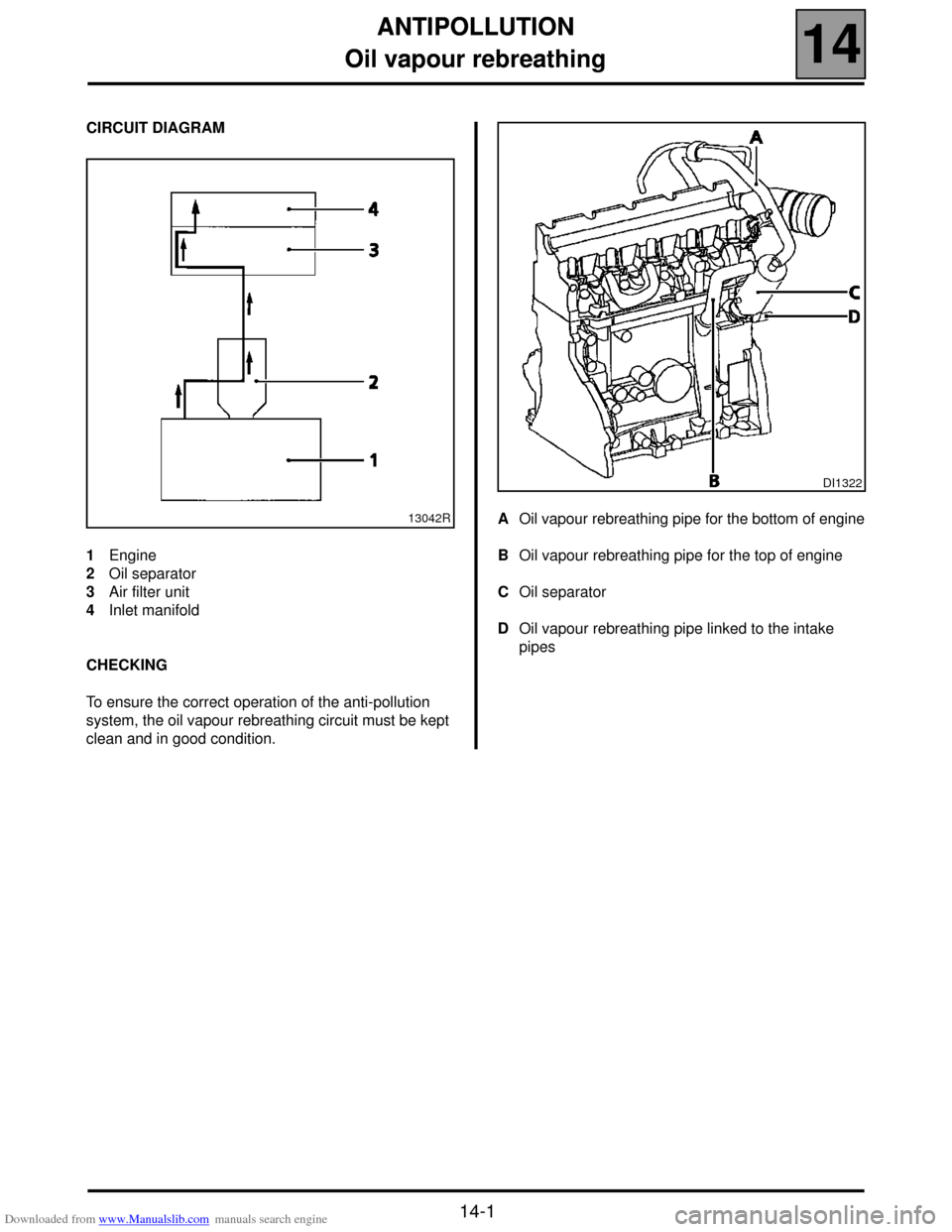
CIRCUIT DIAGRAM
1Engine
2Oil separator
3Air filter unit
4Inlet manifold
CHECKING
To ensure the correct operation of the anti-pollution
system, the oil vapour rebreathing circuit must be kept
clean and in good condition.AOil vapour rebreathing pipe for the bottom of engine
BOil vapour rebreathing pipe for the top of engine
COil separator
DOil vapour rebreathing pipe linked to the intake
pipes
13042R
DI1322
Page 98 of 118

Downloaded from www.Manualslib.com manuals search engine STARTING - CHARGING
Alternator
16
116STARTING - CHARGING
Alternator
IDENTIFICATION
CHECKING
After 15 minutes warming up at a voltage of 13.5 volts. Type Engine Alternator Current
XA0 5 F9Q 732
SG 10 B010
SG 10 B011
A13VI252
A11VI88120 A
80 A
75 A
Rpm. 75 Amps 80 Amps 120 Amps
1 000 40 54 -
1 500 - - 26
2 000 68 75 -
3 000 71 80 -
4 000 72 82 94
6 000 - - 105
16-1
Page 99 of 118
Downloaded from www.Manualslib.com manuals search engine STARTING - CHARGING
Alternator
16
16-2
REMOVAL
Put the vehicle on a 2 post lift.
Disconnect the battery as well as all electrical
connections on the alternator.
Separate the diesel filter from its mounting and
remove.
Unclip the power steering reservoir.
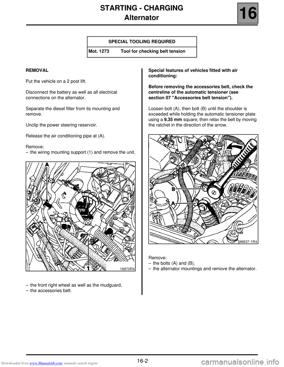
Release the air conditioning pipe at (A).
Remove:
– the wiring mounting support (1) and remove the unit,
– the front right wheel as well as the mudguard,
– the accessories belt.Special features of vehicles fitted with air
conditioning:
Before removing the accessories belt, check the
centreline of the automatic tensioner (see
section 07 "Accessories belt tension").
Loosen bolt (A), then bolt (B) until the shoulder is
exceeded while holding the automatic tensioner plate
using a 9.35 mm square, then relax the belt by moving
the ratchet in the direction of the arrow.
Remove:
– the bolts (A) and (B),
– the alternator mountings and remove the alternator. SPECIAL TOOLING REQUIRED
Mot. 1273 Tool for checking belt tension
16870R4
98837-1R4
Page 102 of 118
Downloaded from www.Manualslib.com manuals search engine STARTING - CHARGING
Starter
16
16-5
REMOVAL
Put the vehicle on a 2 post lift.
Disconnect the battery.
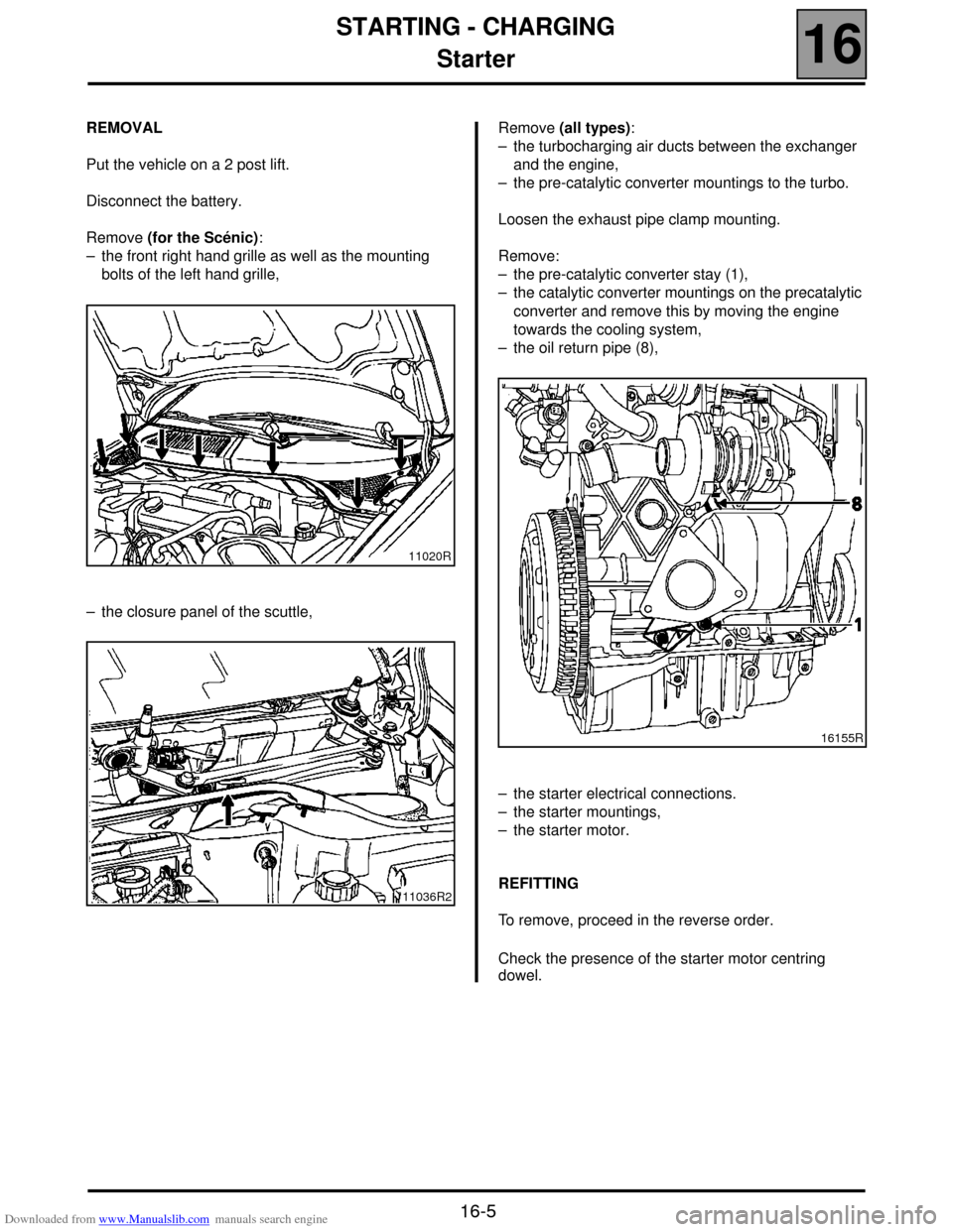
Remove (for the Scénic):
– the front right hand grille as well as the mounting
bolts of the left hand grille,
– the closure panel of the scuttle,Remove (all types):
– the turbocharging air ducts between the exchanger
and the engine,
– the pre-catalytic converter mountings to the turbo.
Loosen the exhaust pipe clamp mounting.
Remove:
– the pre-catalytic converter stay (1),
– the catalytic converter mountings on the precatalytic
converter and remove this by moving the engine
towards the cooling system,
– the oil return pipe (8),
– the starter electrical connections.
– the starter mountings,
– the starter motor.
REFITTING
To remove, proceed in the reverse order.
Check the presence of the starter motor centring
dowel.
11020R
11036R2
16155R
Page 103 of 118

Downloaded from www.Manualslib.com manuals search engine COOLING SYSTEM
Filling and bleeding
19
119 COOLING SYSTEM
Filling and bleeding
There is no heater matrix water control valve.
Water flow is continuous in the heater matrix, which
contributes to the cooling of the engine.
FILLING
It is essential to open the bleed screw on the
cylinder head coolant pipe housing outlet.
Fill the circuit through the expansion bottle opening.
Close the bleed screw as soon as the fluid runs out in
a continuous jet.
Start the engine (2500 rpm).
Adjust the level by overflow for a period of about
4 minutes.
Tighten the expansion bottle cap.
BLEEDING
Let the engine run for 20 minutes at 2500 rpm, until
the engine cooling fan operates (time required for
automatic degassing).
Check the liquid level is at the "Maximum" marker.
DO NOT OPEN THE BLEED SCREW(S) WITH THE
ENGINE RUNNING.
REFIT THE EXPANSION BOTTLE CAP WHILE THE
ENGINE IS WARM.
19-1
Page 111 of 118
Downloaded from www.Manualslib.com manuals search engine MANUAL GEARBOXES
Capacities - Lubricants
21
21-2
521MANUAL GEARBOXES
Capacities - Lubricants
CAPACITY (in litres)
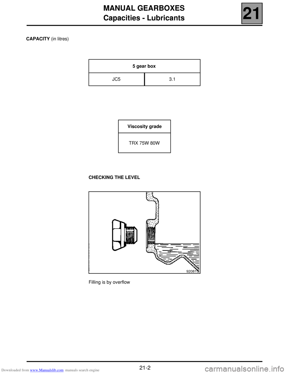
CHECKING THE LEVEL
Filling is by overflow5 gear box
JC5 3.1
Viscosity grade
TRX 75W 80W
92081S
Page 114 of 118
Downloaded from www.Manualslib.com manuals search engine AIR CONDITIONING
Dehydration canister
62
62-3
SCENIC Dehydration canister
REMOVAL
Drain the R134a refrigerant circuit using the filling
equipment (refer to the procedure described in the
"Air Conditioning" manual).
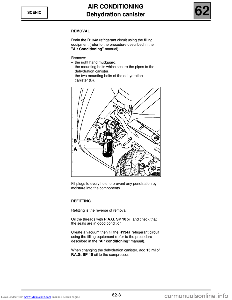
Remove:
– the right hand mudguard,
– the mounting bolts which secure the pipes to the
dehydration canister,
– the two mounting bolts of the dehydration
canister (B).
Fit plugs to every hole to prevent any penetration by
moisture into the components.
REFITTING
Refitting is the reverse of removal.
Oil the threads with P.A.G. SP 10 oil and check that
the seals are in good condition.
Create a vacuum then fill the R134a refrigerant circuit
using the filling equipment (refer to the procedure
described in the "Air conditioning" manual).
When changing the dehydration canister, add 15 ml of
P.A.G. SP 10 oil to the compressor.
16763R
Page 117 of 118
Downloaded from www.Manualslib.com manuals search engine AIR CONDITIONING
Connecting pipes
62
62-6
SCENIC Connecting pipes
Disconnect the battery.
Drain the R134a refrigerant circuit using the filling equipment (refer to the procedure described in the "Air
Conditioning" manual).
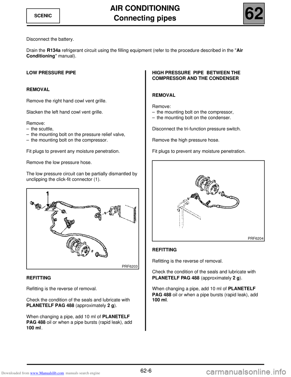
LOW PRESSURE PIPE
REMOVAL
Remove the right hand cowl vent grille.
Slacken the left hand cowl vent grille.
Remove:
– the scuttle,
– the mounting bolt on the pressure relief valve,
– the mounting bolt on the compressor.
Fit plugs to prevent any moisture penetration.
Remove the low pressure hose.
The low pressure circuit can be partially dismantled by
unclipping the click-fit connector (1).
REFITTING
Refitting is the reverse of removal.
Check the condition of the seals and lubricate with
PLANETELF PAG 488 (approximately 2 g).
When changing a pipe, add 10 ml of PLANETELF
PAG 488 oil or when a pipe bursts (rapid leak), add
100 ml.HIGH PRESSURE PIPE BETWEEN THE
COMPRESSOR AND THE CONDENSER
REMOVAL
Remove:
– the mounting bolt on the compressor,
– the mounting bolt on the condenser.
Disconnect the tri-function pressure switch.
Remove the high pressure hose.
Fit plugs to prevent any moisture penetration.
REFITTING
Refitting is the reverse of removal.
Check the condition of the seals and lubricate with
PLANETELF PAG 488 (approximately 2 g).
When changing a pipe, add 10 ml of PLANETELF
PAG 488 oil or when a pipe bursts (rapid leak), add
100 ml.
PRF6203
PRF6204
Page 118 of 118
Downloaded from www.Manualslib.com manuals search engine AIR CONDITIONING
Connecting pipes
62
62-7
SCENIC
Disconnect the battery.
Drain the R134a refrigerant circuit using the filling equipment (refer to the procedure described in the "Air
Conditioning" manual).
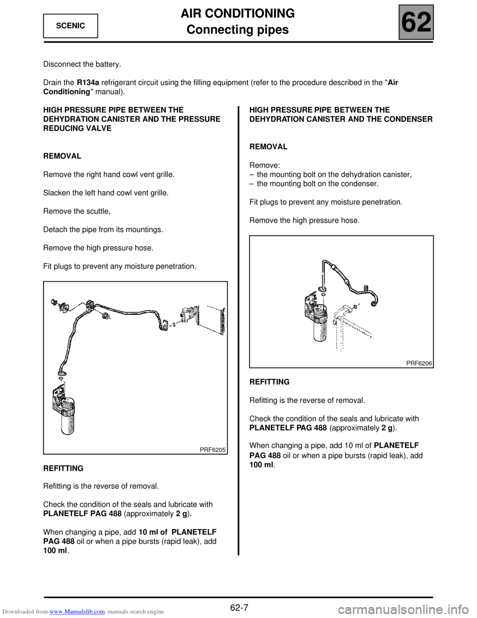
HIGH PRESSURE PIPE BETWEEN THE
DEHYDRATION CANISTER AND THE PRESSURE
REDUCING VALVE
REMOVAL
Remove the right hand cowl vent grille.
Slacken the left hand cowl vent grille.
Remove the scuttle,
Detach the pipe from its mountings.
Remove the high pressure hose.
Fit plugs to prevent any moisture penetration.
REFITTING
Refitting is the reverse of removal.
Check the condition of the seals and lubricate with
PLANETELF PAG 488 (approximately 2 g).
When changing a pipe, add 10 ml of PLANETELF
PAG 488 oil or when a pipe bursts (rapid leak), add
100 ml.HIGH PRESSURE PIPE BETWEEN THE
DEHYDRATION CANISTER AND THE CONDENSER
REMOVAL
Remove:
– the mounting bolt on the dehydration canister,
– the mounting bolt on the condenser.
Fit plugs to prevent any moisture penetration.
Remove the high pressure hose.
REFITTING
Refitting is the reverse of removal.
Check the condition of the seals and lubricate with
PLANETELF PAG 488 (approximately 2 g).
When changing a pipe, add 10 ml of PLANETELF
PAG 488 oil or when a pipe bursts (rapid leak), add
100 ml.
PRF6205
PRF6206