CD changer RENAULT SCENIC 2000 J64 / 1.G Technical Note 3426A Workshop Manual
[x] Cancel search | Manufacturer: RENAULT, Model Year: 2000, Model line: SCENIC, Model: RENAULT SCENIC 2000 J64 / 1.GPages: 118, PDF Size: 1.5 MB
Page 2 of 118
Downloaded from www.Manualslib.com manuals search engine Contents
Page
07
10
11
12
VALUES AND SETTINGS
Capacities - Grades 07-1
Accessories belt tension 07-2
Checking the accessories belt tension 07-3
Tightening the cylinder head 07-5
Tyres and wheels 07-6
Brakes 07-7
Brake compensator 07-8
Underbody height 07-9
Front axle angle checking values 07-11
Rear axle angle checking values 07-13
ENGINE AND PERIPHERALS
Identification 10-1
Oil pressure 10-2
Engine and transmission assembly 10-3
Sump 10-8
TOP AND FRONT OF ENGINE
Timing belt 11-1
Cylinder head gasket 11-6
FUEL MIXTURE
Air inlet 12-1
TURBOCHARGING
Pressure regulating valve 12-2
Pressure adjustment 12-3
Turbocharger 12-4
Air-air exchanger 12-7
Manifolds 12-9
Priming catalytic converter 12-12Page
13
14
DIESEL EQUIPMENT
Technical specifications 13-1
Special features 13-3
Cleanliness 13-6
Location of components 13-9
Injection warning light 13-12
Immobiliser function 13-13
Injection programming/ air conditioning 13-14
Idle speed correction13-16
Pre-postheating control 13-17
Heater plugs 13-18
Thermoplunger 13-19
Low pressure pump (supercharging
pump)13-21
Fuel filter 13-22
High pressure pump 13-23
Injector gallery 13-27
Injectors 13-32
Checking diesel pressure and flow 13-37
Pressure sensor 13-38
Pressure regulator 13-39
Accelerator potentiometer 13-40
Centralised coolant temperature
management 13-41
Computer 13-42
ANTIPOLLUTION
Oil vapour rebreathing 14-1
Exhaust gas recirculation 14-2
Page 21 of 118
Downloaded from www.Manualslib.com manuals search engine ENGINE AND PERIPHERALS
Engine and transmission assembly
10
10-5
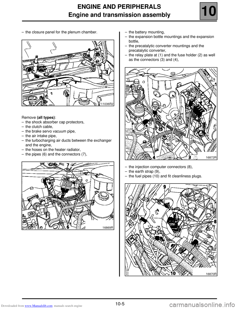
– the closure panel for the plenum chamber.
Remove (all types):
– the shock absorber cap protectors,
– the clutch cable,
– the brake servo vacuum pipe,
– the air intake pipe,
– the turbocharging air ducts between the exchanger
and the engine,
– the hoses on the heater radiator,
– the pipes (6) and the connectors (7),– the battery mounting,
– the expansion bottle mountings and the expansion
bottle,
– the precatalytic converter mountings and the
precatalytic converter,
– the relay plate at (1) and the fuse holder (2) as well
as the connectors (3) and (4),
– the injection computer connectors (8),
– the earth strap (9),
– the fuel pipes (10) and fit cleanliness plugs.
11036R2
16869R
16872R
16870R
Page 39 of 118
Downloaded from www.Manualslib.com manuals search engine FUEL MIXTURE
Air intake
12
112
FUEL MIXTURE
Air intake
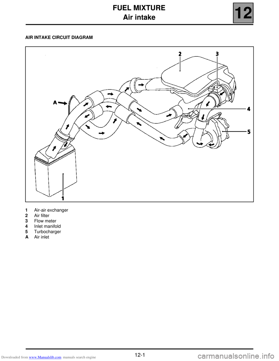
AIR INTAKE CIRCUIT DIAGRAM
1 Air-air exchanger
2 Air filter
3 Flow meter
4 Inlet manifold
5 Turbocharger
A Air inlet
12-1
Page 44 of 118
Downloaded from www.Manualslib.com manuals search engine TURBOCHARGING
Turbocharger
12
12-6
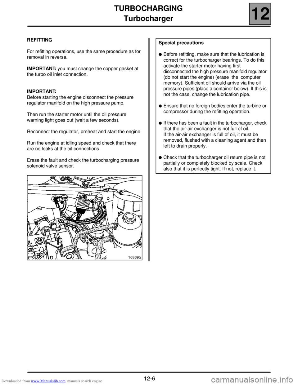
REFITTING
For refitting operations, use the same procedure as for
removal in reverse.
IMPORTANT: you must change the copper gasket at
the turbo oil inlet connection.
IMPORTANT:
Before starting the engine disconnect the pressure
regulator manifold on the high pressure pump.
Then run the starter motor until the oil pressure
warning light goes out (wait a few seconds).
Reconnect the regulator, preheat and start the engine.
Run the engine at idling speed and check that there
are no leaks at the oil connections.
Erase the fault and check the turbocharging pressure
solenoid valve sensor.
16869S
Special precautions
!Before refitting, make sure that the lubrication is
correct for the turbocharger bearings. To do this
activate the starter motor having first
disconnected the high pressure manifold regulator
(do not start the engine) (erase the computer
memory). Sufficient oil should arrive via the oil
pressure pipes (place a container below). If this is
not the case, change the lubrication pipe.
!Ensure that no foreign bodies enter the turbine or
compressor during the refitting operation.
!If there has been a fault in the turbocharger, check
that the air-air exchanger is not full of oil.
If the air-air exchanger is full of oil, it must be
removed, flushed with a cleaning agent and then
left to drain properly.
!Check that the turbocharger oil return pipe is not
partially or completely blocked by scale. Check
also that it is perfectly tight. If not, replace it.
Page 45 of 118
Downloaded from www.Manualslib.com manuals search engine TURBOCHARGING
Air-air exchanger
12
12-7
Air-air exchanger
REMOVAL
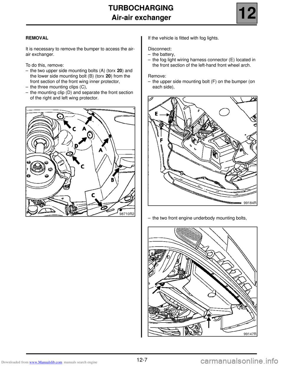
It is necessary to remove the bumper to access the air-
air exchanger.
To do this, remove:
– the two upper side mounting bolts (A) (torx 20) and
the lower side mounting bolt (B) (torx 20) from the
front section of the front wing inner protector,
– the three mounting clips (C),
– the mounting clip (D) and separate the front section
of the right and left wing protector.If the vehicle is fitted with fog lights.
Disconnect:
– the battery,
– the fog light wiring harness connector (E) located in
the front section of the left-hand front wheel arch.
Remove:
– the upper side mounting bolt (F) on the bumper (on
each side),
– the two front engine underbody mounting bolts,
98710R2
99184R
99147R
Page 46 of 118
Downloaded from www.Manualslib.com manuals search engine TURBOCHARGING
Air-air exchanger
12
12-8
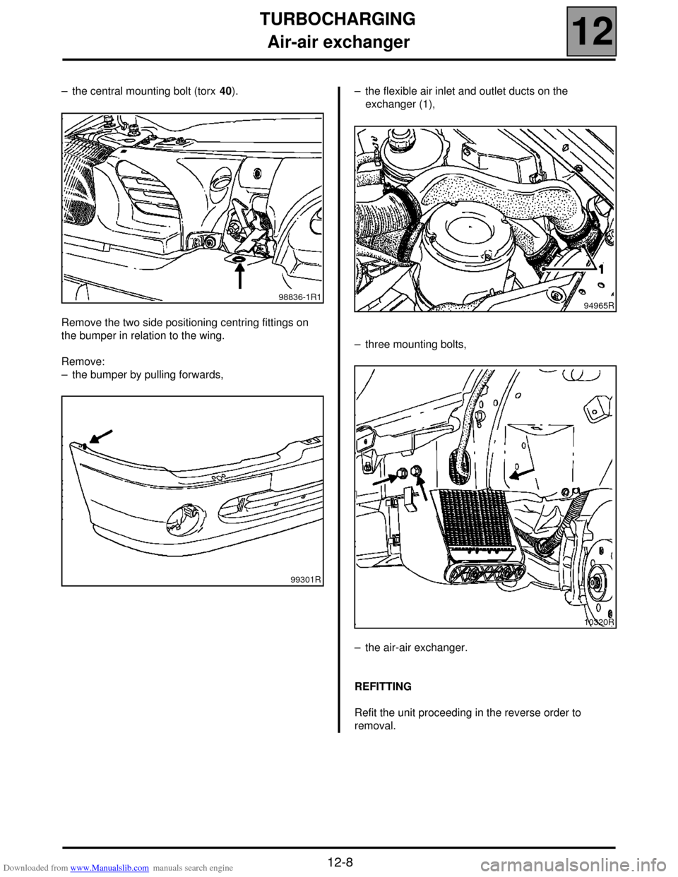
– the central mounting bolt (torx 40).
Remove the two side positioning centring fittings on
the bumper in relation to the wing.
Remove:
– the bumper by pulling forwards,– the flexible air inlet and outlet ducts on the
exchanger (1),
– three mounting bolts,
– the air-air exchanger.
REFITTING
Refit the unit proceeding in the reverse order to
removal.
98836-1R1
99301R94965R
10320R
Page 73 of 118
Downloaded from www.Manualslib.com manuals search engine DIESEL EQUIPMENT
Fuel filter
13
13-22
Fuel filter
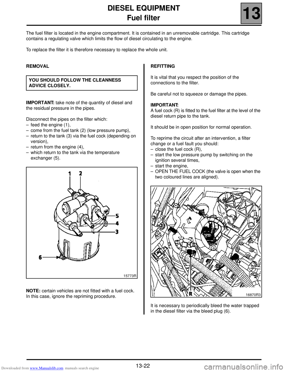
The fuel filter is located in the engine compartment. It is contained in an unremovable cartridge. This cartridge
contains a regulating valve which limits the flow of diesel circulating to the engine.
To replace the filter it is therefore necessary to replace the whole unit.
REMOVAL
IMPORTANT: take note of the quantity of diesel and
the residual pressure in the pipes.
Disconnect the pipes on the filter which:
– feed the engine (1),
– come from the fuel tank (2) (low pressure pump),
– return to the tank (3) via the fuel cock (depending on
version),
– return from the engine (4),
– which return to the tank via the temperature
exchanger (5).
NOTE: certain vehicles are not fitted with a fuel cock.
In this case, ignore the repriming procedure.REFITTING
It is vital that you respect the position of the
connections to the filter.
Be careful not to squeeze or damage the pipes.
IMPORTANT:
A fuel cock (R) is fitted to the fuel filter at the level of the
diesel return pipe to the tank.
It should be in open position for normal operation.
To reprime the circuit after an intervention, a filter
change or a fuel fault you should:
– close the fuel cock (R),
– start the low pressure pump by switching on the
ignition several times,
– start the engine,
– OPEN THE FUEL COCK (the valve is open when the
two coloured lines are aligned).
It is necessary to periodically bleed the water trapped
in the diesel filter via the bleed plug (6). YOU SHOULD FOLLOW THE CLEANNESS
ADVICE CLOSELY.
15773R
16870R3
Page 102 of 118
Downloaded from www.Manualslib.com manuals search engine STARTING - CHARGING
Starter
16
16-5
REMOVAL
Put the vehicle on a 2 post lift.
Disconnect the battery.
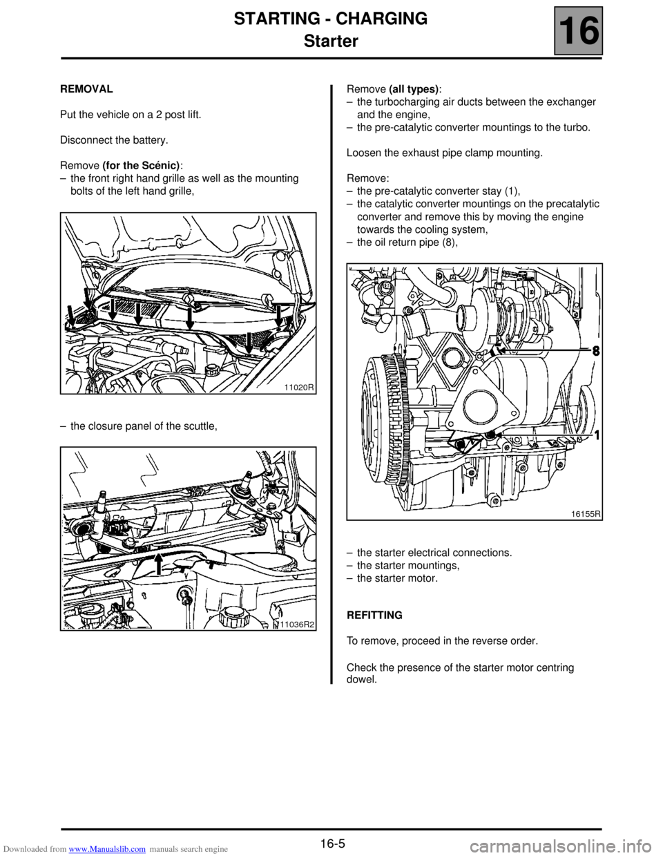
Remove (for the Scénic):
– the front right hand grille as well as the mounting
bolts of the left hand grille,
– the closure panel of the scuttle,Remove (all types):
– the turbocharging air ducts between the exchanger
and the engine,
– the pre-catalytic converter mountings to the turbo.
Loosen the exhaust pipe clamp mounting.
Remove:
– the pre-catalytic converter stay (1),
– the catalytic converter mountings on the precatalytic
converter and remove this by moving the engine
towards the cooling system,
– the oil return pipe (8),
– the starter electrical connections.
– the starter mountings,
– the starter motor.
REFITTING
To remove, proceed in the reverse order.
Check the presence of the starter motor centring
dowel.
11020R
11036R2
16155R
Page 104 of 118
Downloaded from www.Manualslib.com manuals search engine COOLING SYSTEM
Diagram
19
19-2
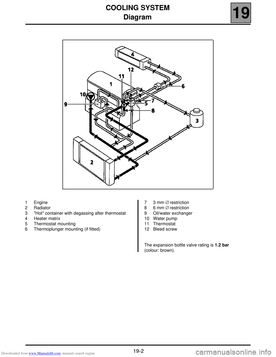
Diagram
1 Engine
2 Radiator
3 "Hot" container with degassing after thermostat
4 Heater matrix
5 Thermostat mounting
6 Thermoplunger mounting (if fitted)7 3 mm ∅ restriction
8 6 mm ∅ restriction
9 Oil/water exchanger
10 Water pump
11 Thermostat
12 Bleed screw
The expansion bottle valve rating is 1.2 bar
(colour: brown).
Page 106 of 118
Downloaded from www.Manualslib.com manuals search engine COOLING SYSTEM
Radiator
19
19-4
Radiator
REMOVAL
Put the vehicle on a two post lift.
Disconnect the battery.
Remove the engine undertray.
Drain the cooling circuit through the lower radiator
hose.
Disconnect the wiring of the fan unit.
Unclip the power steering reservoir and remove it.
Remove:
– the upper cross member,
– the upper radiator mountings,
– the upper hoses on the radiator,
– the inlet manifold-air exchanger duct,
– the fan unit mountings on the radiator and remove
the fan,
– the radiator mountings on the condenser and remove
the radiator.REFITTING
Refitting is the reverse of removal.
Fill and bleed the cooling circuit (see section 19
"Filling and bleeding").
NOTE: ensure that the fins of the radiator or of the
condenser (if fitted) are not damaged when
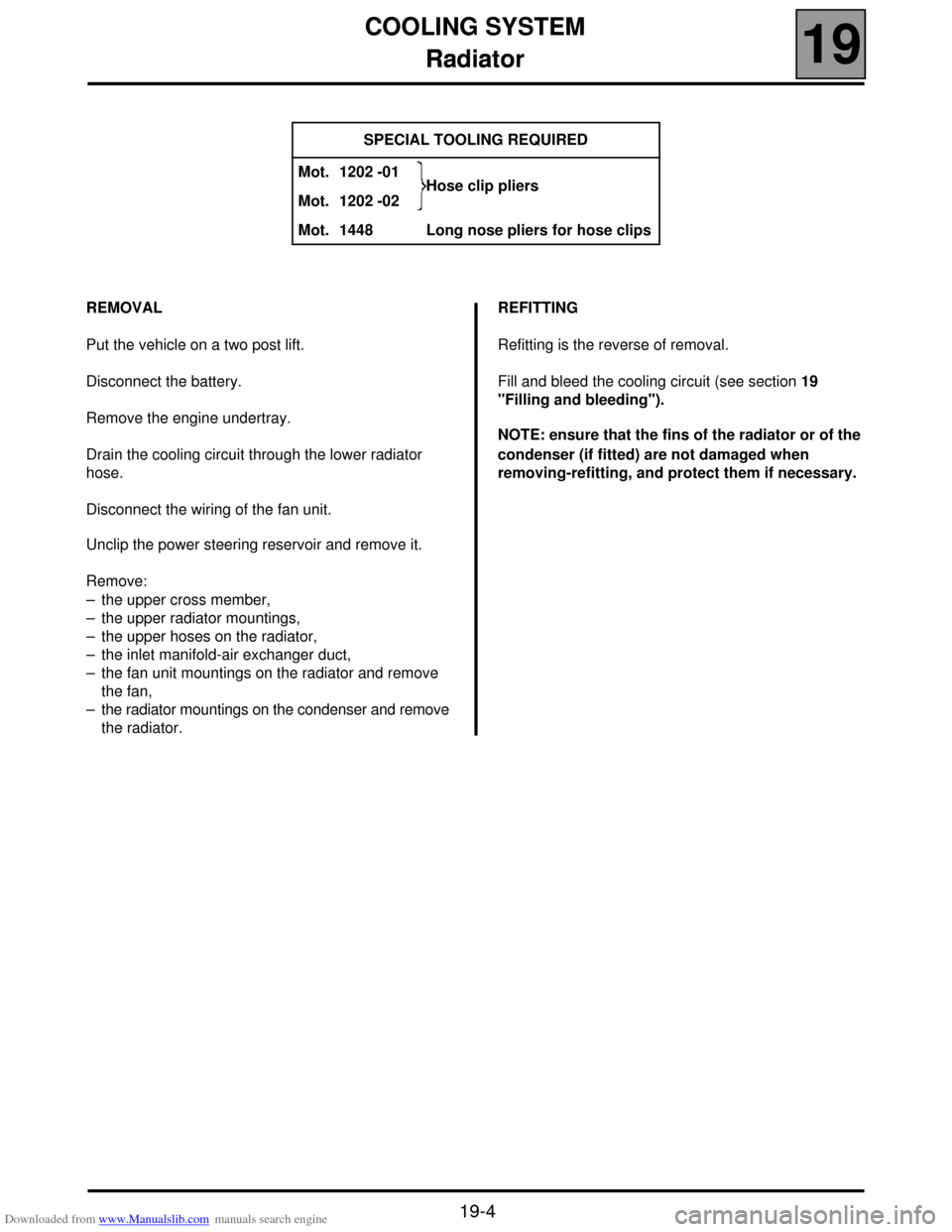
removing-refitting, and protect them if necessary. SPECIAL TOOLING REQUIRED
Mot. 1202 -01
Hose clip pliers
Mot. 1202 -02
Mot. 1448 Long nose pliers for hose clips