fuse chart RENAULT SCENIC 2007 J84 / 2.G Automatic Transmission Siemens TA2005 Workshop Manual
[x] Cancel search | Manufacturer: RENAULT, Model Year: 2007, Model line: SCENIC, Model: RENAULT SCENIC 2007 J84 / 2.GPages: 139, PDF Size: 0.43 MB
Page 128 of 139

Fault finding - Fault Finding Chart23A
23A -128V5 MR-372-J84-23A100$928.mif
SIEMENS TA2005
Vdiag No.: 14-18AUTOMATIC TRANSMISSION
Fault finding - Fault Finding Chart
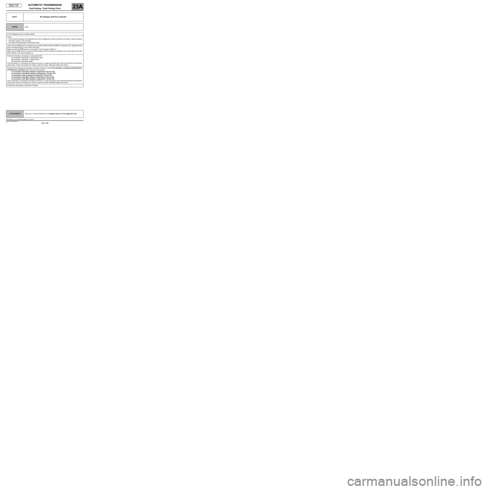
ALP1 No dialogue with the computer
NOTESNone.
Try the diagnostic tool on another vehicle.
Check:
–the connection between the diagnostic tool and the diagnostic socket (connection and cable in good condition),
–the power supply to the computer,
–the engine and passenger compartment fuses.
Check that the CLIP sensor is supplied by connections BP32, MAN and NAM of component 225, displayed when
both red indicator lights on the sensor illuminate.
Make sure that the CLIP sensor is connected to the computer's USB port.
Make sure the CLIP sensor is communicating properly with the vehicle's computers; this can be seen by the two
green diodes on the sensor lighting up.
Check the following connections on component 225:
●connection code AP43 (+ after ignition feed),
●connection code BP32 (+ battery feed),
●connection code MAN (earth).
If the connection or connections are faulty and there is a repair procedure (see Technical Note 6015A, Electrical
wiring repair, Wiring: Precautions for repair), repair the wiring. Otherwise replace the wiring.
Disconnect the automatic transmission computer connector to check the insulation, continuity and the absence
of interference resistance of the following connections:
●connection code AP4, between components 119 and 1337,
●connection code BP42, between components 119 and 1337,
●connection code N, between components 119 and 107,
●connection code 3MT, between components 119 and 120,
●connection code 3MS, between components 119 and 120,
If the connection or connections are faulty and there is a repair procedure (see Technical Note 6015A, Electrical
wiring repair, Wiring: Precautions for repair), repair the wiring. Otherwise replace the wiring.
If the fault is still present, contact the Techline.
AFTER REPAIRCarry out a road test followed by a complete check with the diagnostic tool.
DP0TA2005_V14_ALP01/DP0TA2005_V18_ALP01
MR-372-J84-23A100$928.mif
Page 135 of 139

AUTOMATIC TRANSMISSION
Fault finding - Fault Finding Chart23A
23A -135V5 MR-372-J84-23A100$928.mif
SIEMENS TA2005
Vdiag No.: 14-18
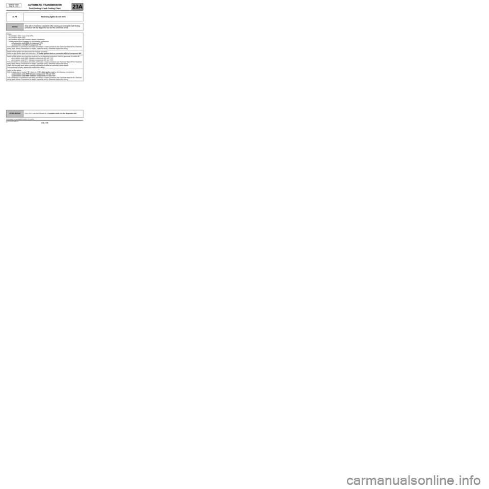
ALP6 Reversing lights do not work
NOTESOnly refer to Customer complaints after carrying out a complete fault finding
procedure with the diagnostic tool and the conformity check.
Check:
–the condition of the fuses in the UPC.
–the condition of the bulbs.
–the condition of the bulb contacts. Repair if necessary.
–Check that the earth is present for the following connections:
●connection code MAQ of component 172,
●connection code MZ of component 173.
If the connection or connections are faulty and there is a repair procedure (see Technical Note 6015A, Electrical
wiring repair, Wiring: Precautions for repair), repair the wiring. Otherwise replace the wiring.
Switch off the ignition and disconnect the modular connector.
Switch on the ignition again and check for + 12 V after ignition feed on connection AP11 of component 485.
Switch off the ignition and check the continuity on the following connections, with the gear lever in position R:
●connection code H66P, between components 485 and 1337,
●connection code AP11, between components 485 and 1337.
If the connection or connections are faulty and there is a repair procedure (see Technical Note 6015A, Electrical
wiring repair, Wiring: Precautions for repair), repair the wiring. Otherwise replace the wiring.
Check that the gear lever cable is correctly adjusted and check the instrument panel display.
If the continuity is faulty, replace the multifunction switch.
Switch on the ignition.
With the gear lever in position "R", check for + 12 V after ignition feed on the following connections:
●connection code H66P between components 172 and 1337,
●connection code H66P, between components 173 and 1337.
If the connection or connections are faulty and there is a repair procedure (see Technical Note 6015A, Electrical
wiring repair, Wiring: Precautions for repair), repair the wiring. Otherwise replace the wiring.
AFTER REPAIRCarry out a road test followed by a complete check with the diagnostic tool.
DP0TA2005_V14_ALP06/DP0TA2005_V18_ALP06