86D-11V1 MR-372-J84-86D050$040.mif
86D
BIC
Vdiag No.: 14
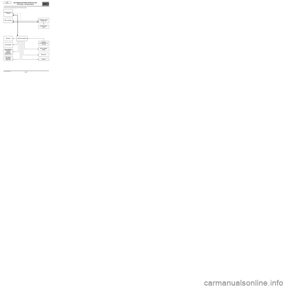
Layout of the main components of the LPN* Radio system:
Diagnostic socket
V M CAN
Other computersMultimedia network
interface unit
Steering column
control
GPS aerial LPN radio navigation
Passenger
compartment fuse box
and relay
Aerial amplifier
Radio navigation
display
ABS, ABS/ESP or
wheel speed
computer
depending on
equipment level
Microphone
CD changer
(depending on
equipment)Speakers
MULTIMEDIA NETWORK INTERFACE UNIT
Fault finding – Operating diagram
86D-37
AFTER REPAIRWhen communication is established, deal with any faults indicated.
V1 MR-372-J84-86D050$160.mif
86D
BIC
Vdiag No.: 14
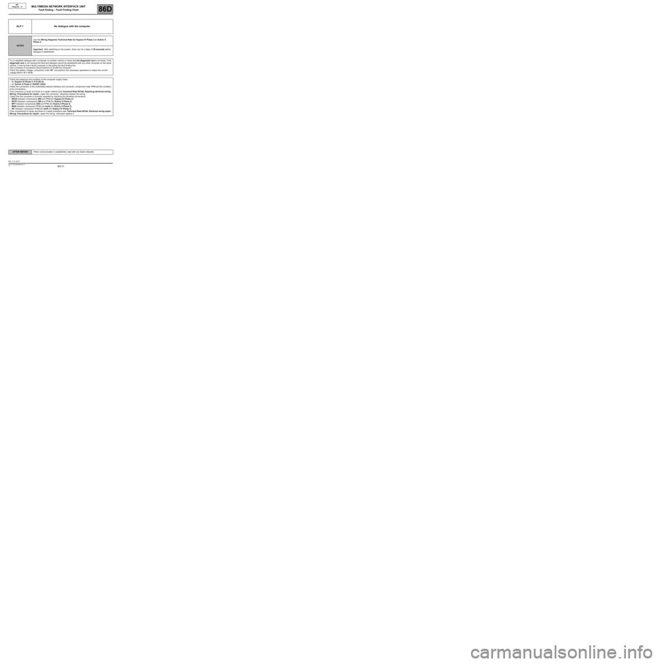
ALP 1 No dialogue with the computer
NOTESUse the Wiring Diagrams Technical Note for Espace IV Phase 2 or Scénic II
Phase 2.
Important: After switching on the system, there can be a delay of 20 seconds before
dialogue is established.
Try to establish dialogue with a computer on another vehicle to check that the diagnostic tool is not faulty. If the
diagnostic tool is not causing the fault and dialogue cannot be established with any other computer on the same
vehicle, it may be that a faulty computer is disrupting the fault finding line.
Use a process of successive disconnections to locate this computer.
Check the battery voltage, component code 107, and perform the necessary operations to obtain the correct
voltage (12 V < X < 15 V).
Check the presence and condition of the computer supply fuses:
–for Espace IV Phase 2: F15 (30 A),
–for Scénic II Phase 2: SHUNT (2AA).
Check the connection of the multimedia network interface unit connector, component code 1714 and the condition
of its connections.
If the connector is faulty and there is a repair method (see Technical Note 6015A, Repairing electrical wiring,
Wiring: Precautions for repair), repair the connector, otherwise replace the wiring.
Check that the computer is correctly supplied by checking the following connections:
•BP3A between components 260 and 1714 (for Espace IV Phase 2),
•BCP3 between components 260 and 1714 (for Scénic II Phase 2),
•BPT between components 645 and 1714 (for Scénic II Phase 2),
•MAN between component 1714 and earth (for Scénic II Phase 2),
•NC between component 1714 and earth (for Espace IV Phase 2).
If the connection(s) is faulty and there is a repair procedure (see Technical Note 6015A, Electrical wiring repair,
Wiring: Precautions for repair), repair the wiring, otherwise replace it.
BIC_V14_ALP1
MULTIMEDIA NETWORK INTERFACE UNIT
Fault finding – Fault Finding Chart

