alternator RENAULT SCENIC 2008 J84 / 2.G Engine And Peripherals - Starting Charging Workshop Manual
[x] Cancel search | Manufacturer: RENAULT, Model Year: 2008, Model line: SCENIC, Model: RENAULT SCENIC 2008 J84 / 2.GPages: 21, PDF Size: 0.08 MB
Page 2 of 21
16A-2V1 MR-372-J84-16A000$010.mif
16A
Scénic II ph 2
•Battery
The principal purpose of the battery is to provide the powerful current briefly required by the starter motor to start the
engine. For optimum starting, the current supplied by the battery must be sent to the starter motor with minimum
loss. To achieve this, the electrical connections (wires, terminals, connectors, etc.) must be in good condition.
When the engine is not running, the battery must feed the accessories that operate constantly, even with the ignition
switched off, such as the alarm, radio codes, computers, etc.
•Starter
This turns the engine over to make it start, and requires a very powerful electric current, which the battery must be
able to supply.
•Alternator
The alternator only operates when the engine is running. Its function is to recharge the battery, and at the same time
to supply the electrical power required to operate all the electrical accessories on the vehicle.
The alternator on Mégane II phase 2 is a controlled alternator. The UPC* controls the regulation via a serial
connection.
•Engine Compartment Connection Unit or Protection and Switching Unit
The UPC* is connected to the alternator by a serial connection. The UPC* intelligently manages the alternator
regulation voltage according to the engine phase, the battery charge, and the temperature.
•The UCH
The UCH* interprets the starting request and analyses if the starting conditions are satisfied, in order to transmit the
request to the UPC*.
*UPC: Engine Compartment Connection Unit or Protection and Switching Unit
*UCH: Passenger Compartment Central Unit
STARTING - CHARGING
Fault finding – Role of components
Page 3 of 21
16A-3V1 MR-372-J84-16A000$020.mif
16A
Scénic II ph 2
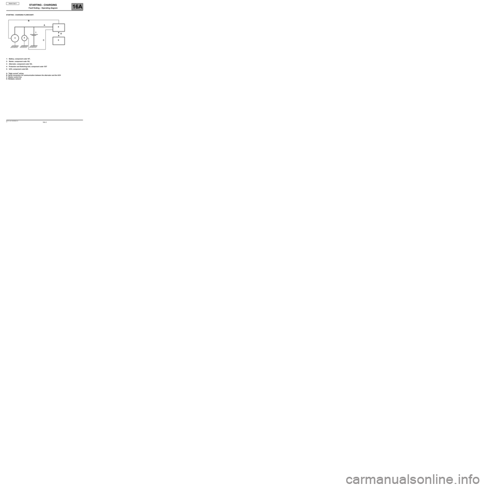
STARTING - CHARGING FLOWCHART:
1- Battery, component code 107,
2- Starter, component code 163,
3- Alternator, component code 103,
4- Protection and Switching Unit, component code 1337
5- UCH, component code 645.
A. "High current" wiring
B. Serial connection for communication between the alternator and the UCH
C. Starter control line
D. Multiplex network
4
5D
C 1A
2
3B
STARTING - CHARGING
Fault finding – Operating diagram
Page 4 of 21
16A-4V1 MR-372-J84-16A000$030.mif
16A
Scénic II ph 2
The function of the charging circuit is to:
•Ensure that electrical energy is supplied to the vehicle whilst respecting the dynamic performance constraints of
the engine and transmission assembly: the alternator resisting torques and the torque gradients measured must
be managed.
•To control alternator loading and load shedding during engine management authorisation or variation of the
electrical load.
•To ensure the quality of the on board network voltage in terms of the voltage level and variation (voltage gradient
management).
•To optimise the battery charge by applying a voltage to its terminals correlating to its initial charge status (in sleep
mode) and to its internal temperature.
•To inform the engine management about the mechanical power taken from the accessories pulley, the alternator
charge rate and the rotor excitation current value.
•To run fault finding on the charging circuit: "Battery" warning light display.
The function of the starting circuit is to:
•start the vehicle when there is a starting request from the ignition key.
STARTING - CHARGING
Fault finding – Features
Page 15 of 21
16A-15V1 MR-372-J84-16A000$060.mif
16A
Scénic II ph 2
NOTESPerform this test only after running complete fault finding on the Engine compartment
connection unit using the diagnostic tool (see 87G, Engine compartment
connection unit).
Because the Engine compartment connection unit houses the CHARGING CIRCUIT
function (sub-function: alternator) and checks the alternator via a serial connection.
CHARGING
ALTERNATOR SUPPLY TESTTEST 1
POWER FUSE AND WIRING
TEST THE CONDITION OF THE POWER FUSE AND THE CAUSE OF ITS FAULT TEST 2
WIRING HARNESS CHECKTEST 3
STARTING - CHARGING
Fault finding – Tests
Page 16 of 21
16A-16V1 MR-372-J84-16A000$060.mif
STARTING - CHARGING
Fault finding – Tests16A
Scénic II ph 2
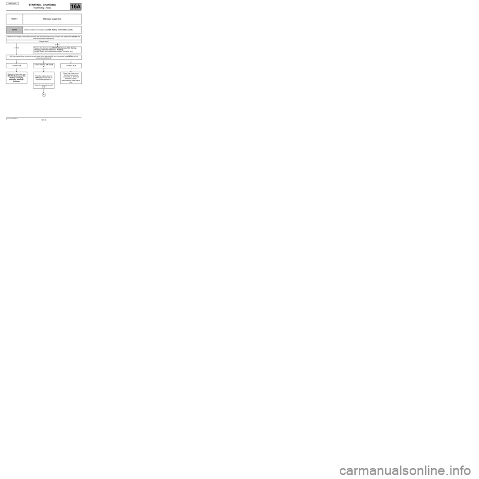
TEST 1 Alternator supply test
NOTESTest the condition of the battery (see 80A, Battery, Test 1 Battery check).
Measure the voltage at the battery terminals with the engine warm and running at idle speed for 2 minutes and
with all consumers switched off.
Voltage value?
Replace the alternator (see MR 370, Mechanical, 16A, Starting -
Charging, Alternator: Removal - Refitting).
Visually inspect the consequences (battery, corrosion, etc.).
With the engine idling, connect a current clamp to the alternator B+ wire, connection code BPDA, with all
consumers switched off.
Current < 5 ACurrent between 5 A and 35
ACurrent > 35 A
Replace the alternator (see
MR 370, Mechanical, 16A,
Starting - Charging,
Alternator: Removal -
Refitting).Keep the engine speed at
3000 rpm and still with no
consumers switched on.Check that there are no
electrical components
consuming an abnormal
amount of current.
Disconnect the fuses one by
one.
Value of measured current?
(i 1)
< 16 V
≥ 16 V
A
Page 17 of 21
16A-17V1 MR-372-J84-16A000$060.mif
STARTING - CHARGING
Fault finding – Tests16A
Scénic II ph 2
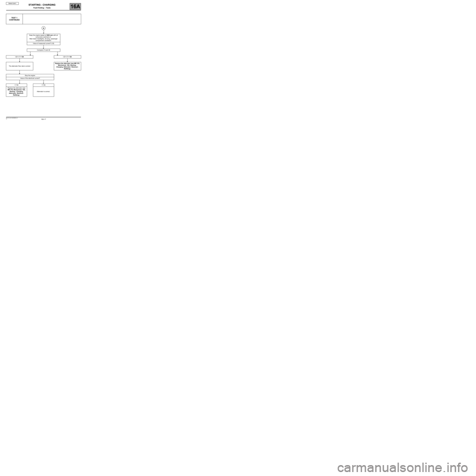
TEST 1
CONTINUED
Keep the engine speed at 3000 rpm with all
consumers switched on.
Main beam headlights, de-icing, passenger
compartment ventilation.
Value of measured current? (i 2)
Compare i 1 and i 2
i 2 > i 1 + 5A i 2 < i 1 + 5A
The alternator flow rate is correctReplace the alternator (see MR 370,
Mechanical, 16A, Starting -
Charging, Alternator: Removal -
Refitting).
Stop the engine
Value of the electrical current?
> 1 A < 1 A
Replace the alternator (see
MR 370, Mechanical, 16A,
Starting - Charging,
Alternator: Removal -
Refitting).Alternator is correct.
A
Page 18 of 21
16A-18V1 MR-372-J84-16A000$060.mif
STARTING - CHARGING
Fault finding – Tests16A
Scénic II ph 2
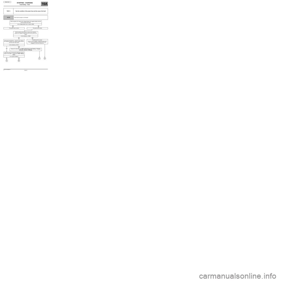
TEST 2 Test the condition of the power fuse and the cause of its fault
NOTESCheck that the engine is not blocked.
With the ignition off, measure the voltage between the negative battery terminal
and the power fuse output
Is the voltage greater than or equal to 10V?
The power fuse is correct The power fuse is faulty
With the battery disconnected, measure the resistance
between the negative battery terminal and the power fuse
output
Is the resistance
≥ 10 ΩΩ Ω Ω
?
Disconnect the alternator + terminal, then measure
the resistance between the negative battery terminal
and the power fuse outputPossible external causes:
use of a "starter charger", excessively long use of
starter (e.g.: activating the starter with the gear
engaged to move the vehicle) etc.
Is the resistance
≥ 10 Ω?
Replace the alternator (see MR 370, Mechanical, 16A, Starting - Charging,
Alternator: Removal - Refitting).
Check the wiring connecting the alternator and the
starter to the battery + terminal (see TEST 3 Wiring
check).
Is it in good condition?
YESNO
NOYES
D
NO
YES
CNO
A
YES
B
Page 21 of 21
16A-21V1 MR-372-J84-16A000$060.mif
STARTING - CHARGING
Fault finding – Tests16A
Scénic II ph 2
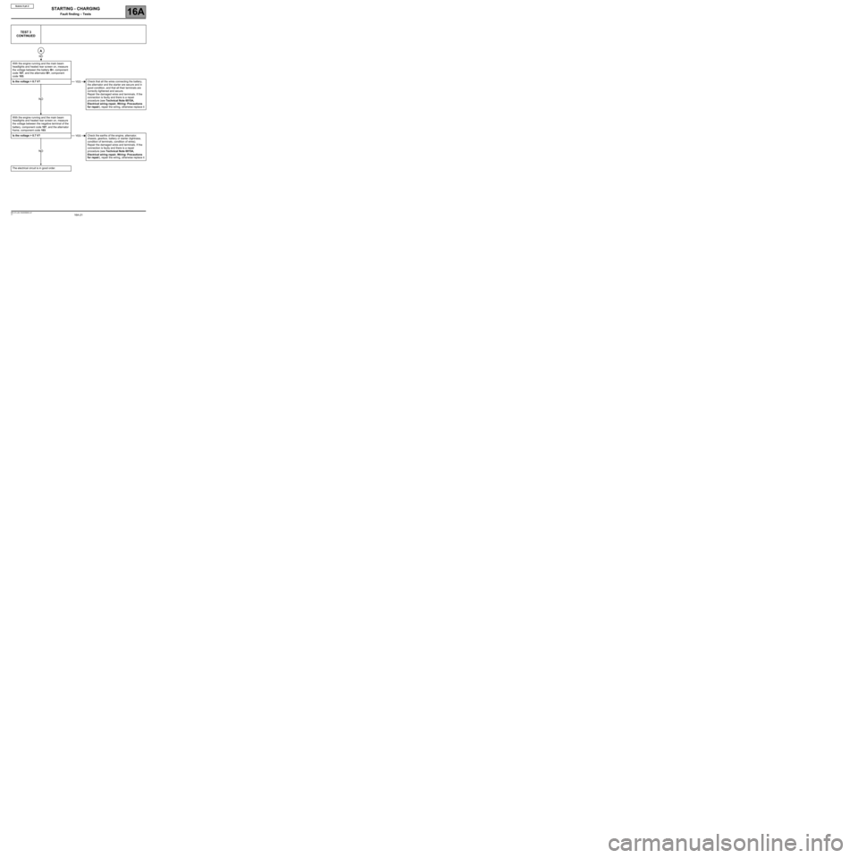
TEST 3
CONTINUED
With the engine running and the main beam
headlights and heated rear screen on, measure
the voltage between the battery B+, component
code 107, and the alternator B+, component
code 103.
Is the voltage > 0.7 V?Check that all the wires connecting the battery,
the alternator and the starter are secure and in
good condition, and that all their terminals are
correctly tightened and secure.
Repair the damaged wires and terminals. If the
connection is faulty and there is a repair
procedure (see Technical Note 6015A,
Electrical wiring repair, Wiring: Precautions
for repair), repair the wiring, otherwise replace it
With the engine running and the main beam
headlights and heated rear screen on, measure
the voltage between the negative terminal of the
battery, component code 107, and the alternator
frame, component code 103.
Is the voltage > 0.7 V?Check the earths of the engine, alternator,
chassis, gearbox, battery or starter (tightness,
condition of terminals, condition of wires).
Repair the damaged wires and terminals. If the
connection is faulty and there is a repair
procedure (see Technical Note 6015A,
Electrical wiring repair, Wiring: Precautions
for repair), repair the wiring, otherwise replace it
The electrical circuit is in good order.
A
NO
YES
NO
YES
NO