RENAULT SCENIC 2009 J84 / 2.G Engine And Peripherals EDC16 Workshop Manual
Manufacturer: RENAULT, Model Year: 2009, Model line: SCENIC, Model: RENAULT SCENIC 2009 J84 / 2.GPages: 273
Page 141 of 273
DIESEL INJECTION
Fault finding – Conformity check13B
13B - 141V3 MR-372-J84-13B250$450.mif
EDC16
PROGRAM NO.: C1
Vdiag No.: 51
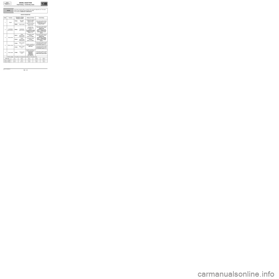
DRIVER PARAMETERS
NOTESOnly check conformity after a complete check using the diagnostic tool. The values
shown in this conformity check are given as a guide.
Test conditions: ENGINE OFF, IGNITION ON.
Order FunctionParameter or Status
checked or ActionDisplay and Notes Fault finding
1EnginePR190:Idle speed
setpointIndicates the engine's
rotational speed
setpoint in rpm.In the event of a fault, refer to
the interpretation for fault
DF005 Engine speed
sensor circuit.
PR055:Engine speedGives the engine's
speed in rpm
2Accelerator
pedal position *PR030:Accelerator
pedal positionIndicates the
accelerator pedal
position.
If no pressure is being
applied to the pedal
PR030 = 0 %In the event of a fault, refer to
the interpretation of fault
DF008 Pedal
potentiometer circuit
gang 1 or DF009 Pedal
potentiometer circuit
gang 2.
3Sensor feedPR147:Pedal
potentiometer
voltage gang 1Accelerator pedal
released
0.70 < X < 0.80 VIn the event of a fault, refer to
the interpretation of fault
DF008 Pedal
potentiometer voltage
track 1 or DF009 Pedal
potentiometer voltage
track 2. PR148:Pedal
potentiometer
voltage gang 2Accelerator pedal
released
0.35 < X < 0.40 V
4Brake contactET704:Brake contact
no. 1
Indicates recognition of
brake pedal contacts
INACTIVEIn the event of a fault, consult
the interpretation of status
ET704 Brake switch no. 1.
ET705:Brake contact
no. 2In the event of a fault, consult
the interpretation for status
ET705 Brake switch no. 2.
5Clutch pedalET405:Clutch pedal
switchIndicates recognition of
clutch pedal contacts
RELEASED
(MANUAL)
or WITHOUT
(AUTOMATIC)In the event of a fault, consult
the interpretation of status
ET405 Clutch pedal switch.
(*) Pedal voltages - cold, ignition on (average values stated for information only).
Pedal load 0 % 25 % 50 % 100 % 120 %
Gang 1 voltage 0.74 V 1.52 V 2.09 V 3.23 V 3.67 V
Gang 2 voltage 0.37 V 0.77 V 1.06 V 1.64 V 1.87 V
Page 142 of 273
DIESEL INJECTION
Fault finding – Conformity check13B
13B - 142V3 MR-372-J84-13B250$450.mif
EDC16
PROGRAM NO.: C1
Vdiag No.: 51
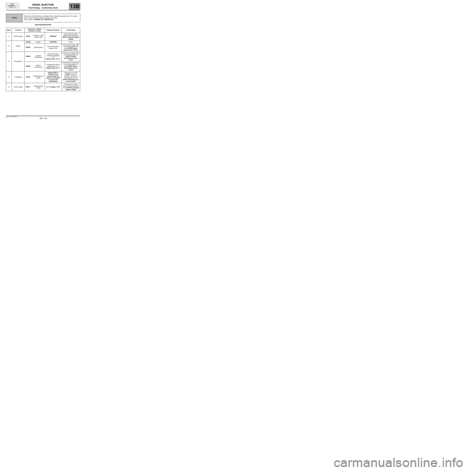
IGNITION/PREHEATING
NOTESOnly check conformity after a complete check using the diagnostic tool. The values
shown in this conformity check are given as a guide.
Test conditions: ENGINE OFF, IGNITION ON.
Order FunctionParameter or Status
checked or ActionDisplay and Notes Fault finding
1Power supplyET001:Computer + after
ignition feedPRESENTIn the event of a fault,
perform fault finding for
DF047 Computer supply
voltage.
2EngineET038:EngineSTOPPEDNone
PR055:Engine speedGives the engine's
speed in rpmIn the event of a fault, refer
to the interpretation for
fault DF005 Engine
speed sensor circuit.
3TemperaturePR064:Coolant
temperatureShows the engine
coolant temperature
in ˚C
Default value: 119 ˚CIn the event of a fault, refer
to the interpretation of
DF001 Coolant
temperature sensor
circuit.
PR059:Inlet air
temperatureIndicates the inlet air
temperature in ˚C
Default value: 20 ˚CIn the event of a fault, refer
to the interpretation of
fault DF039 Inlet air
temperature sensor
circuit
4PreheatingET007:Preheating unit
controlStatus ET007 is
ACTIVE a few
seconds after the
ignition is switched
on and for the
postheatingIn the event of a fault
(ET007 locked on
ACTIVE), consult the
interpretation of fault
DF017 Preheating unit
control circuit.
5Power supplyPR071:Computer feed
voltage9 V < voltage < 16 VIn the event of a fault,
consult the interpretation
of fault DF047 computer
supply voltage.
Page 143 of 273
DIESEL INJECTION
Fault finding – Conformity check13B
13B - 143V3 MR-372-J84-13B250$450.mif
EDC16
PROGRAM NO.: C1
Vdiag No.: 51
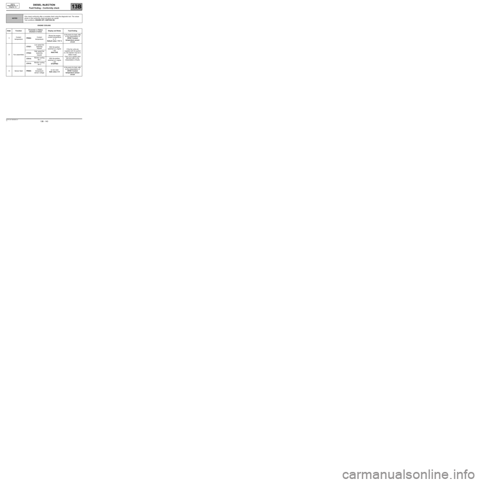
ENGINE COOLING
NOTESOnly check conformity after a complete check using the diagnostic tool. The values
shown in this conformity check are given as a guide.
Test conditions: ENGINE OFF, IGNITION ON.
Order FunctionParameter or Status
checked or ActionDisplay and Notes Fault finding
1Coolant
temperaturePR064:Coolant
temperatureShows the engine
coolant temperature
in ˚C
Default value: 119 ˚CIn the event of a fault, refer
to the interpretation of
DF001 Coolant
temperature sensor
circuit.
2Fan assembliesET021:Low speed fan
assembly
requestWith the ignition
switched on, engine
< 80˚
INACTIVEIf the fan units are
supplied with the ignition
on, the injection may be in
defect mode.
Carry out a system fault
test and refer to the
interpretation of faults. ET022:High speed fan
assembly
request
ET014:Monitor cooling
fan 1With the ignition
switched on, engine
< 80˚
STOPPED ET015:Monitor cooling
fan 2
3Sensor feedPR084:Coolant
temperature
sensor voltage3 < X < 4 V
Safe value: 5 VIn the event of a fault, refer
to the interpretation of
DF001 Coolant
temperature sensor
circuit.
Page 144 of 273
DIESEL INJECTION
Fault finding – Conformity check13B
13B - 144V3 MR-372-J84-13B250$450.mif
EDC16
PROGRAM NO.: C1
Vdiag No.: 51
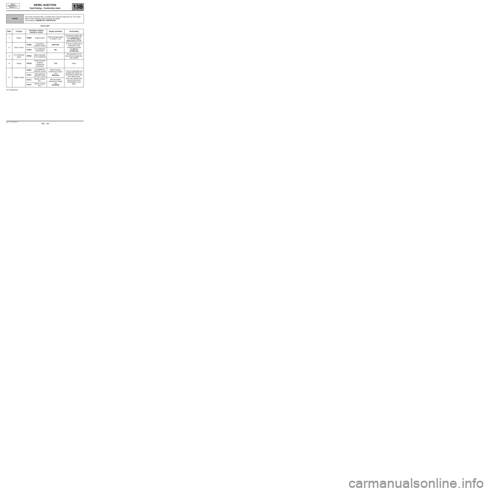
COLD LOOP
*Air Conditioning
NOTESOnly check conformity after a complete check using the diagnostic tool. The values
shown in this conformity check are given as a guide.
Test conditions: ENGINE OFF, IGNITION ON.
Order FunctionParameter or Status
checked or ActionDisplay and Notes Fault finding
1EnginePR055:Engine speedGives the engine speed
of rotation in rpmIn the event of a fault, refer
to the interpretation for
fault DF005 Engine
speed sensor circuit.
2Driver controlET088:Compressor
actuation requestINACTIVEIf the air conditioning is
authorised or the
compressor actuated
see 62A air
conditioning. ET004:Air conditioning
authorisationNO
3Air conditioning
speedPR053:Speed requested
by air conditioningThis parameter is only
valid when the engine has
been started
4OutputPR125:Power absorbed
by the air
conditioning
compressor*0 WNone
5Engine coolingET022:Low speed fan
assembly requestWith the ignition
switched on, engine
< 80˚
INACTIVEIf the fan assemblies are
supplied with ignition on,
the injection system may
be in defect mode.
Carry out a system fault
test and refer to the
interpretation of any
faults. ET021:High speed fan
assembly request
ET014:Monitor cooling
fan 1With the ignition
switched on, engine
< 80˚
STOPPED ET015:Monitor cooling
fan 2
Page 145 of 273
DIESEL INJECTION
Fault finding – Conformity check13B
13B - 145V3 MR-372-J84-13B250$450.mif
EDC16
PROGRAM NO.: C1
Vdiag No.: 51
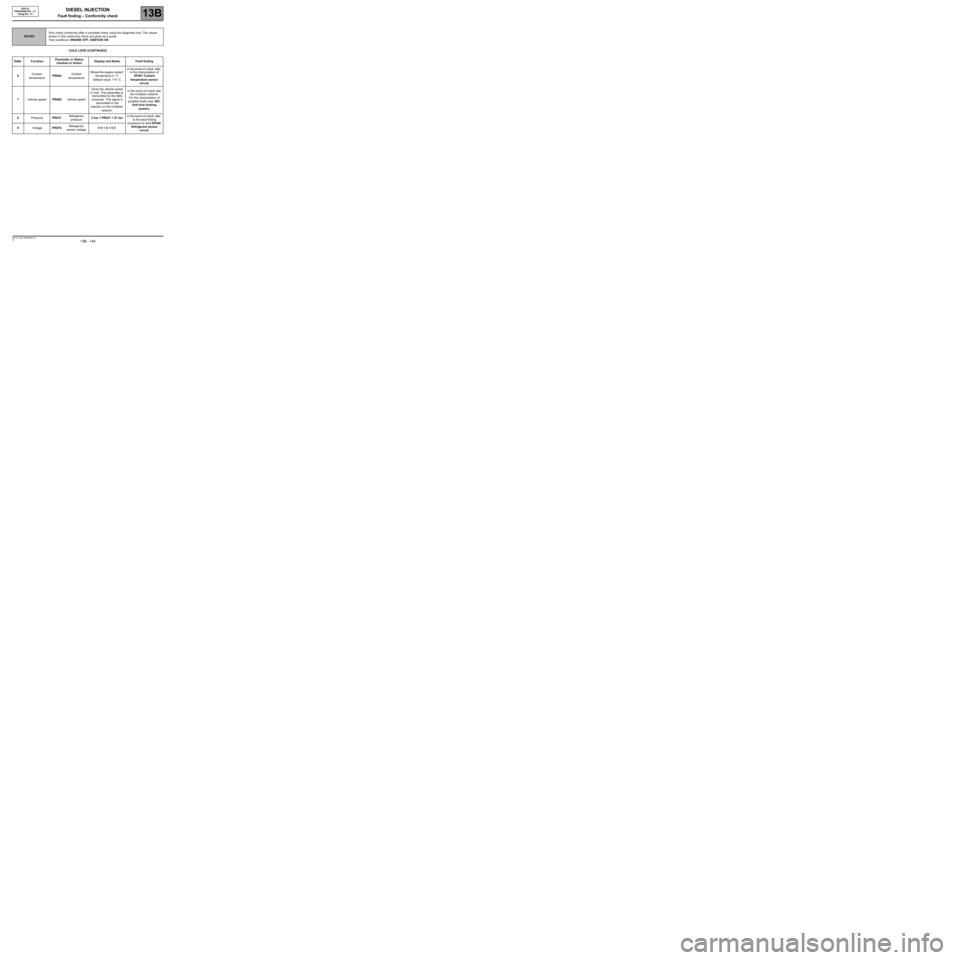
COLD LOOP (CONTINUED)
NOTESOnly check conformity after a complete check using the diagnostic tool. The values
shown in this conformity check are given as a guide.
Test conditions: ENGINE OFF, IGNITION ON.
Order FunctionParameter or Status
checked or ActionDisplay and Notes Fault finding
6Coolant
temperaturePR064:Coolant
temperatureShows the engine coolant
temperature in ˚C
Default value: 119 ˚CIn the event of a fault, refer
to the interpretation of
DF001 Coolant
temperature sensor
circuit.
7Vehicle speedPR089:Vehicle speedGives the vehicle speed
in mph. This parameter is
transmitted by the ABS
computer. This signal is
transmitted to the
injection on the multiplex
network.In the event of a fault, test
the multiplex network.
For the interpretation of
possible faults (see 38C,
Anti-lock braking
system).
8PressurePR037:Refrigerant
pressure2 bar < PR037 < 27 barIn the event of a fault, refer
to the fault finding
procedure for fault DF049
Refrigerant sensor
circuit. 9VoltagePR076:Refrigerant
sensor voltage0 V < X < 5 V
Page 146 of 273
DIESEL INJECTION
Fault finding – Conformity check13B
13B - 146V3 MR-372-J84-13B250$450.mif
EDC16
PROGRAM NO.: C1
Vdiag No.: 51
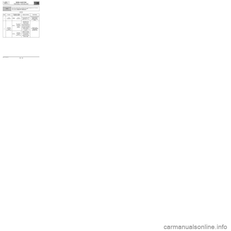
HEATING
NOTESOnly check conformity after a complete check using the diagnostic tool. The values
shown in this conformity check are given as a guide.
Test conditions: ENGINE OFF, IGNITION ON.
Order FunctionParameter or Status
checked or ActionDisplay and Notes Fault finding
1Coolant
temperaturePR064:Coolant
temperatureShows the engine coolant
temperature in ˚C
Default value: 119 ˚CIn the event of a fault, refer
to the interpretation of
DF001 Coolant
temperature sensor
circuit.
2Passenger
Compartment
Heating
Resistors (RCH)ET111:Set number of
Passenger
Compartment
Heating
ResistorsDepending on the
requirements of the
injection system
(e.g. torque reduction,
power requirements), the
injection computer sets
the number of activated
passenger compartment
heating resistors
(no more or no fewer than
required)If there is a fault,
(see 87B, Passenger
compartment
connection unit).
ET112:Passenger
Compartment
Heating
Resistor cut-offStatus ET112 shows
whether the injection
computer has requested
the passenger
compartment heating
resistors to be cut out
ET112 = YES
Page 147 of 273
DIESEL INJECTION
Fault finding – Conformity check13B
13B - 147V3 MR-372-J84-13B250$450.mif
EDC16
PROGRAM NO.: C1
Vdiag No.: 51
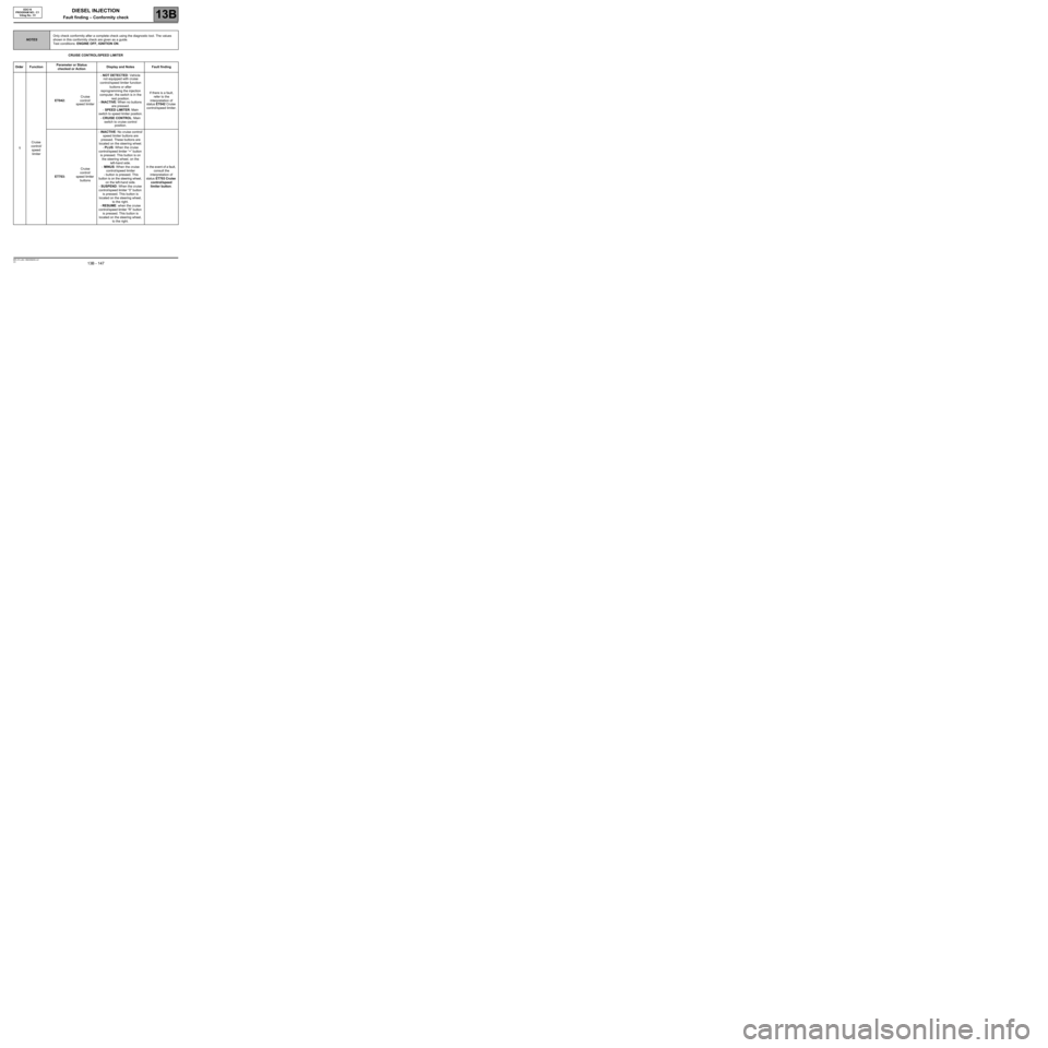
CRUISE CONTROL/SPEED LIMITER
NOTESOnly check conformity after a complete check using the diagnostic tool. The values
shown in this conformity check are given as a guide.
Test conditions: ENGINE OFF, IGNITION ON.
Order FunctionParameter or Status
checked or ActionDisplay and Notes Fault finding
1Cruise
control/
speed
limiterET042: Cruise
control/
speed limiter- NOT DETECTED: Vehicle
not equipped with cruise
control/speed limiter function
buttons or after
reprogramming the injection
computer, the switch is in the
rest position.
- INACTIVE: When no buttons
are pressed.
- SPEED LIMITER: Main
switch to speed limiter position.
- CRUISE CONTROL: Main
switch to cruise control
position.If there is a fault,
refer to the
interpretation of
status ET042 Cruise
control/speed limiter.
ET703: Cruise
control/
speed limiter
buttons- INACTIVE: No cruise control/
speed limiter buttons are
pressed. These buttons are
located on the steering wheel.
- PLUS: When the cruise
control/speed limiter “+” button
is pressed. This button is on
the steering wheel, on the
left-hand side.
- MINUS: When the cruise
control/speed limiter
- button is pressed. This
button is on the steering wheel,
on the left-hand side.
- SUSPEND: When the cruise
control/speed limiter “0” button
is pressed. This button is
located on the steering wheel,
to the right.
- RESUME: when the cruise
control/speed limiter “R” button
is pressed. This button is
located on the steering wheel,
to the right.In the event of a fault,
consult the
interpretation of
status ET703 Cruise
control/speed
limiter button.
Page 148 of 273
DIESEL INJECTION
Fault finding – Conformity check13B
13B - 148V3 MR-372-J84-13B250$450.mif
EDC16
PROGRAM NO.: C1
Vdiag No.: 51
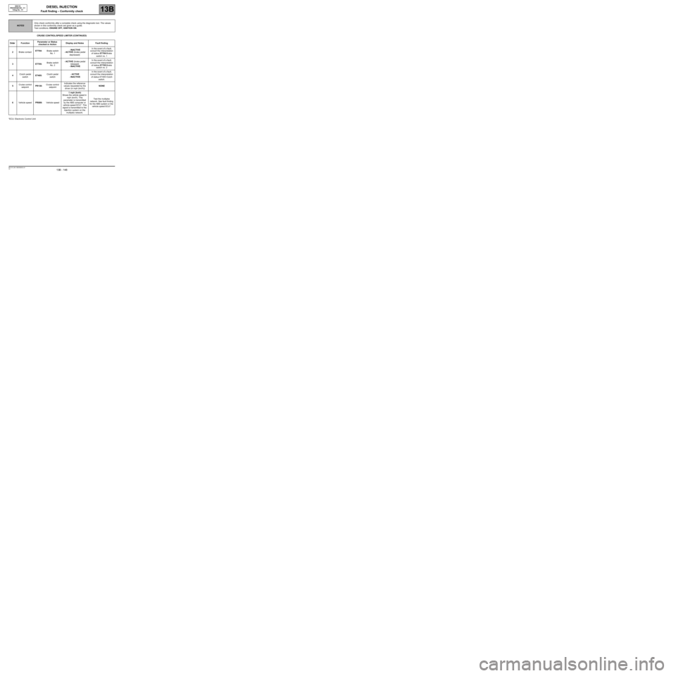
CRUISE CONTROL/SPEED LIMITER (CONTINUED)
*ECU: Electronic Control Unit
NOTESOnly check conformity after a complete check using the diagnostic tool. The values
shown in this conformity check are given as a guide.
Test conditions: ENGINE OFF, IGNITION ON.
Order FunctionParameter or Status
checked or ActionDisplay and Notes Fault finding
2Brake contactET704:Brake switch
No. 1- INACTIVE
- ACTIVE (brake pedal
depressed)In the event of a fault,
consult the interpretation
of status ET704 Brake
switch no. 1
3ET705: Brake switch
No. 2- ACTIVE (brake pedal
released)
- INACTIVEIn the event of a fault,
consult the interpretation
of status ET705 Brake
switch no. 2
4Clutch pedal
switchET405:Clutch pedal
switch- ACTIVE
- INACTIVEIn the event of a fault,
consult the interpretation
of status ET405 Clutch
switch.
5Cruise control
setpointPR130:Cruise control
setpointIndicates the reference
values requested by the
driver (in mph (km/h))NONE
6Vehicle speedPR089:Vehicle speed0 mph (kmh)
Shows the vehicle speed in
mph (km/h). This
parameter is transmitted
by the ABS computer or
vehicle speed ECU*. This
signal is transmitted to the
injection system on the
multiplex network.Test the multiplex
network. See fault finding
for the ABS system or the
vehicle speed ECU*.
Page 149 of 273
DIESEL INJECTION
Fault finding – Conformity check13B
13B - 149V3 MR-372-J84-13B250$450.mif
EDC16
PROGRAM NO.: C1
Vdiag No.: 51
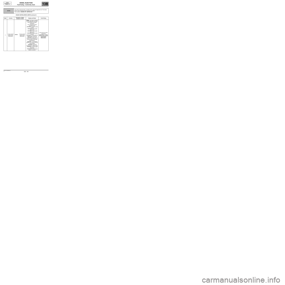
CRUISE CONTROL/SPEED LIMITER (continued 2)
NOTESOnly check conformity after a complete check using the diagnostic tool. The values
shown in this conformity check are given as a guide.
Test conditions: ENGINE OFF, IGNITION ON.
Order FunctionParameter or Status
checked or ActionDisplay and Notes Fault finding
7Cruise control/
speed limiter
deactivationET415:Cruise control/
speed limiter
deactivationNONE: This status is present
on the diagnostic tool when:
the computer has been
reinitialised,
The computer has been
reprogrammed.
- STATUS 1: Traction control
request
- STATUS 2: Brake pedal
depressed.
- STATUS 3: Clutch pedal
depressed.
- STATUS 4: Cancel button
pressed
- STATUS 5: Cruise control or
speed limiter monitoring.
- STATUS 6: Gear lever in
neutral (manual gearbox) or
neutral position (automatic
transmission).
- STATUS 7: Inconsistency
between the request and the
vehicle speed.
- STATUS 8: Automatic
transmission in defect mode.
- STATUS 9: Vehicle speed
monitoring.
- STATUS 10: Monitoring by
injection computer.In the event of a fault,
consult the
interpretation of status
ET415 Cruise control/
speed limiter
deactivation.
Page 150 of 273
DIESEL INJECTION
Fault finding – Conformity check13B
13B - 150V3 MR-372-J84-13B250$450.mif
EDC16
PROGRAM NO.: C1
Vdiag No.: 51
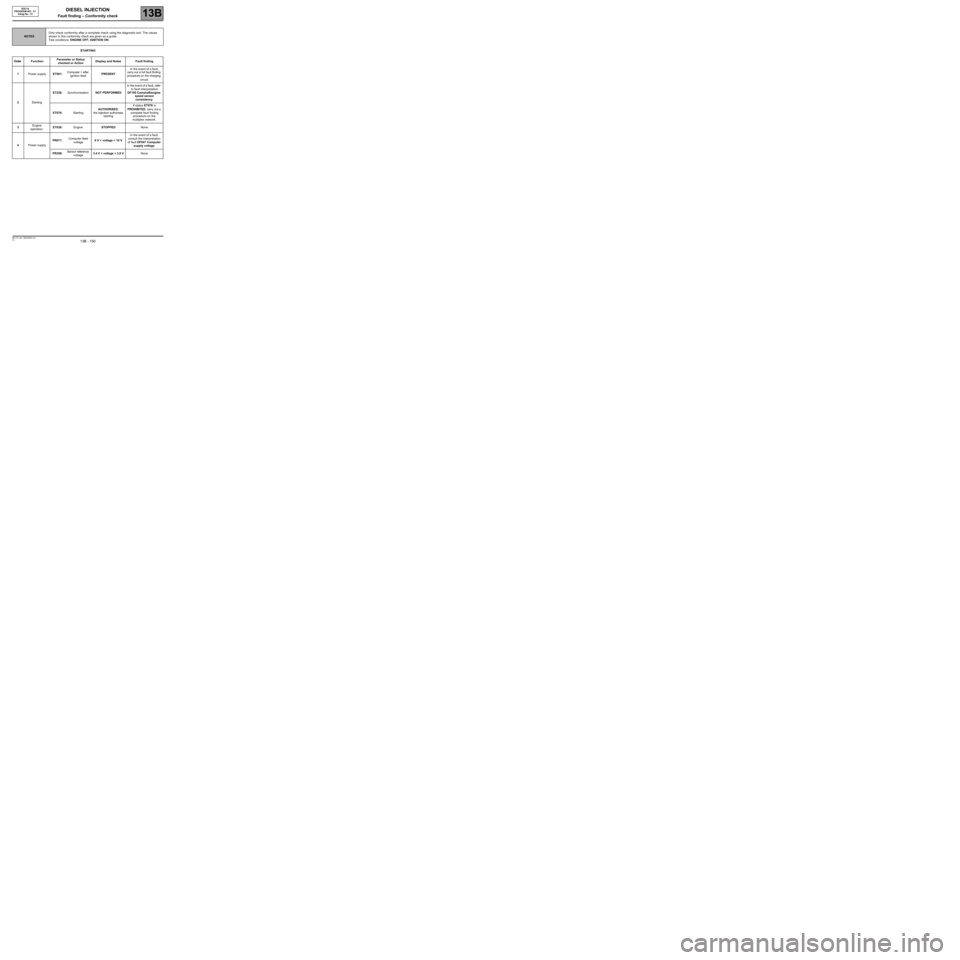
STARTING
NOTESOnly check conformity after a complete check using the diagnostic tool. The values
shown in this conformity check are given as a guide.
Test conditions: ENGINE OFF, IGNITION ON.
Order FunctionParameter or Status
checked or ActionDisplay and Notes Fault finding
1Power supplyET001:Computer + after
ignition feedPRESENTIn the event of a fault,
carry out a full fault finding
procedure on the charging
circuit.
2StartingET238:SynchronisationNOT PERFORMEDIn the event of a fault, refer
to fault interpretation
DF195 Camshaft/engine
speed sensor
consistency.
ET076:StartingAUTHORISED:
the injection authorises
startingIf status ET076 is
PROHIBITED, carry out a
complete fault finding
procedure on the
multiplex network.
3Engine
operation.ET038:EngineSTOPPEDNone
4Power supplyPR071:Computer feed
voltage9 V < voltage < 16 VIn the event of a fault,
consult the interpretation
of fault DF047 Computer
supply voltage.
PR358:Sensor reference
voltage3.4 V < voltage < 3.8 VNone