RENAULT SCENIC 2009 J84 / 2.G Engine And Peripherals EDC16 Workshop Manual
Manufacturer: RENAULT, Model Year: 2009, Model line: SCENIC, Model: RENAULT SCENIC 2009 J84 / 2.GPages: 273
Page 131 of 273
DIESEL INJECTION
Fault finding – Interpretation of faults13B
13B -131V3 MR-372-J84-13B250$450.mif
EDC16
PROGRAM No.: C1
Vdiag No.: 51
DF778
CONTINUED
Check the continuity, the absence of interference resistance, and the insulation to +5 V and +12 V of the
following connections:
–connection code 3ABS,
–connection code 3ABT.
Between components 120 and 1589.
Check the continuity, the absence of interference resistance, and the insulation to earth of connection 3ABS
between components 120 and 1589.
Check for earth on connection 3ABT of the turbine upstream temperature sensor.
If the connection or connections are faulty and there is a repair method (see Technical Note 6015A, Repairing
electrical wiring, Wiring: Precautions for repair), repair the wiring, otherwise replace it.
If the fault is still present, replace the turbine upstream temperature sensor.
AFTER REPAIRDeal with any faults.
Carry out a road test followed by another check with the diagnostic tool.
Page 132 of 273
DIESEL INJECTION
Fault finding – Interpretation of faults13B
13B -132V3 MR-372-J84-13B250$450.mif
EDC16
PROGRAM No.: C1
Vdiag No.: 51
DF1070
PRESENT
OR
STOREDCOLD LOOP
NOTESConditions for applying the fault finding procedure to a stored fault:
The fault is declared present with the engine running and with a heating and air
conditioning system request.
Priorities when dealing with a number of faults:
–DF049 Refrigerant sensor circuit if it is present or stored.
When the fault is present or stored, the heating and air conditioning system is inhibited.
Check fuse F22 (10A) of the UPC and the condition of the air conditioning compressor connector.
If the connector is faulty and there is a repair method (see Technical Note 6015A, Repairing electrical wiring,
Wiring: Precautions for repair), repair the connector, otherwise replace the wiring.
Check the air conditioning compressor wiring.
If the wiring is faulty and there is a repair procedure (see Technical Note 6015A, Repairing electrical wiring,
Wiring: Precautions for repair), repair the wiring, otherwise replace the wiring.
Manually check if the compressor is jammed (turn the clutch plate manually to check that there is no point of
resistance). In the event of sticking, replace the air conditioning compressor (see MR 364 (Mégane II) or 370
(Scénic II), Mechanical, Heating and air conditioning system, 62A, Air conditioning, Compressor: Removal
- Refitting).
Top up the refrigerant, check for any leaks and repair if necessary (see MR 364 (Mégane II) or 370 (Scénic II),
Mechanical, Heating and air conditioning system, 62A, Air conditioning, Refrigerant circuit: check,
Refrigerant circuit: Draining - Filling).
AFTER REPAIRDeal with any faults.
Carry out a road test followed by another check with the diagnostic tool.
EDC16_V51_DF1070
Page 133 of 273
DIESEL INJECTION
Fault finding – Conformity check13B
13B - 133V3 MR-372-J84-13B250$450.mif
EDC16
PROGRAM NO.: C1
Vdiag No.: 51DIESEL INJECTION
Fault finding – Conformity check
MAIN COMPUTER STATUSES AND PARAMETERS
NOTESOnly check conformity after a complete check using the diagnostic tool. The values
shown in this conformity check are given as a guide.
Test conditions: ENGINE OFF, IGNITION ON.
Order FunctionParameter or Status
checked or ActionDisplay and Notes Fault finding
1Vehicle impactET077:Impact
detectedNOIn the event of a fault, refer
to the interpretation of
fault DF069 Impact
detected signal.
2Power supplyET001:Computer
+ after ignition
feedPRESENTIn the event of a fault, refer
to the interpretation of
DF015 Main relay
control circuit.
PR071:Computer
feed voltage9 V < X < 16 VIn the event of a fault,
carry out a fault finding
procedure on the charging
circuit and refer to the
interpretation for DF047
Computer supply
voltage.
PR358:Sensor
reference
voltage3.4 V < X <3.8 VNone
3SpeedPR190:Engine idle
speed
setpoint.Indicates the engine's
rotational speed setpoint
in rpm.In the event of a fault, refer
to the interpretation for
fault DF005 Engine
speed sensor circuit.
PR055:Engine speedGives the engine's rotational
speed in rpm.
With the ignition on
at 0 rpm
4Speed signalPR089:Vehicle
speedGives the vehicle speed in
mph. This parameter is
transmitted by the ABS
computer. This signal is
transmitted to the injection
on the multiplex network.In the event of a fault, test
the multiplex network.
(See 88B, Multiplexing).
EDC16_V51_CCONF
MR-372-J84-13B250$450.mif
Page 134 of 273
DIESEL INJECTION
Fault finding – Conformity check13B
13B - 134V3 MR-372-J84-13B250$450.mif
EDC16
PROGRAM NO.: C1
Vdiag No.: 51
MAIN COMPUTER STATUSES AND PARAMETERS (CONTINUED)
NOTESOnly check conformity after a complete check using the diagnostic tool. The values
shown in this conformity check are given as a guide.
Test conditions: ENGINE OFF, IGNITION ON.
Order FunctionParameter or Status
checked or ActionDisplay and Notes Fault finding
5Injection
configurationET104:Injector code useYESThis status indicates that
the IMA function is
activated. In the event of a
fault, consult the
interpretation of DF276
Injector code
programming.
6PressurePR035:Atmospheric
pressureIndicates the
atmospheric pressure
in mbar.
The sensor is built
into the computer.
Default value:
750 mbar.In the event of a fault,
consult the interpretation
of DF003 Atmospheric
pressure sensor circuit.
PR038:Rail pressure0 < X < 30 barIn the event of a fault,
consult the interpretation
of fault DF007 Rail
pressure sensor circuit.
7
TemperaturePR059:Inlet air
temperatureShows the inlet air
temperature
Ignition on PR061 =
PR059
Default value: 20 ˚CIn the event of a fault, refer
to the interpretation for
DF039 Inlet air
temperature circuit
sensor
8PR064:Coolant
temperatureShows the engine
coolant temperature
in ˚C
Default value: 119 ˚CIn the event of a fault, refer
to the interpretation of
DF001 Coolant
temperature sensor
circuit.
9TorquePR015:Engine torqueThis parameter is only
valid when the engine has
been started.
10Charging circuitPR016:Alternator flow0 mAIn the event of a fault,
check the charging circuit.
Page 135 of 273
DIESEL INJECTION
Fault finding – Conformity check13B
13B - 135V3 MR-372-J84-13B250$450.mif
EDC16
PROGRAM NO.: C1
Vdiag No.: 51
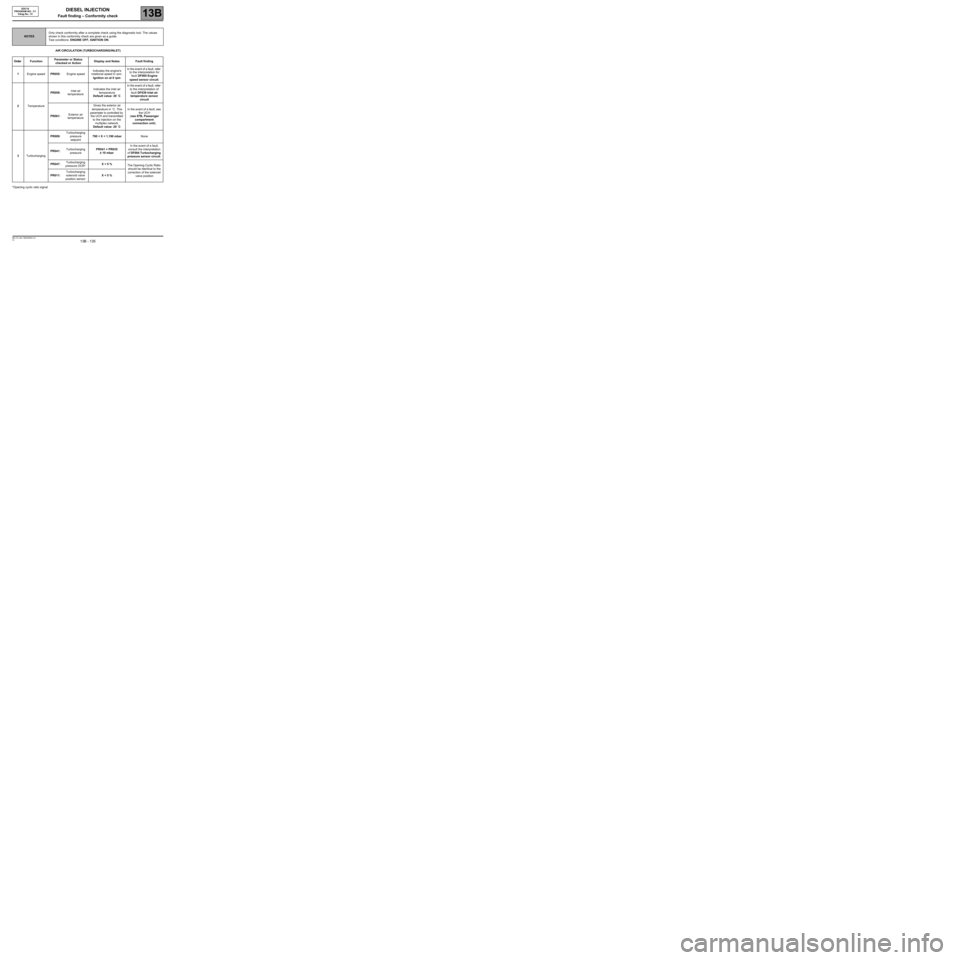
AIR CIRCULATION (TURBOCHARGING/INLET)
*Opening cyclic ratio signal
NOTESOnly check conformity after a complete check using the diagnostic tool. The values
shown in this conformity check are given as a guide.
Test conditions: ENGINE OFF, IGNITION ON.
Order FunctionParameter or Status
checked or ActionDisplay and Notes Fault finding
1Engine speedPR055:Engine speedIndicates the engine's
rotational speed in rpm.
Ignition on at 0 rpmIn the event of a fault, refer
to the interpretation for
fault DF005 Engine
speed sensor circuit.
2TemperaturePR059:Inlet air
temperatureIndicates the inlet air
temperature
Default value: 20 ˚CIn the event of a fault, refer
to the interpretation of
fault DF039 Inlet air
temperature sensor
circuit
PR061:Exterior air
temperatureGives the exterior air
temperature in ˚C. This
parameter is controlled by
the UCH and transmitted
to the injection on the
multiplex network.
Default value: 20 ˚CIn the event of a fault, see
the UCH
(see 87B, Passenger
compartment
connection unit).
3TurbochargingPR009:Turbocharging
pressure
setpoint790 < X < 1,190 mbarNone
PR041:Turbocharging
pressurePR041 = PR035
± 10 mbarIn the event of a fault,
consult the interpretation
of DF004 Turbocharging
pressure sensor circuit.
PR047:Turbocharging
pressure OCR*X < 5 %
The Opening Cyclic Ratio
should be identical to the
correction of the solenoid
valve position PR011:Turbocharging
solenoid valve
position sensorX < 5 %
Page 136 of 273
DIESEL INJECTION
Fault finding – Conformity check13B
13B - 136V3 MR-372-J84-13B250$450.mif
EDC16
PROGRAM NO.: C1
Vdiag No.: 51
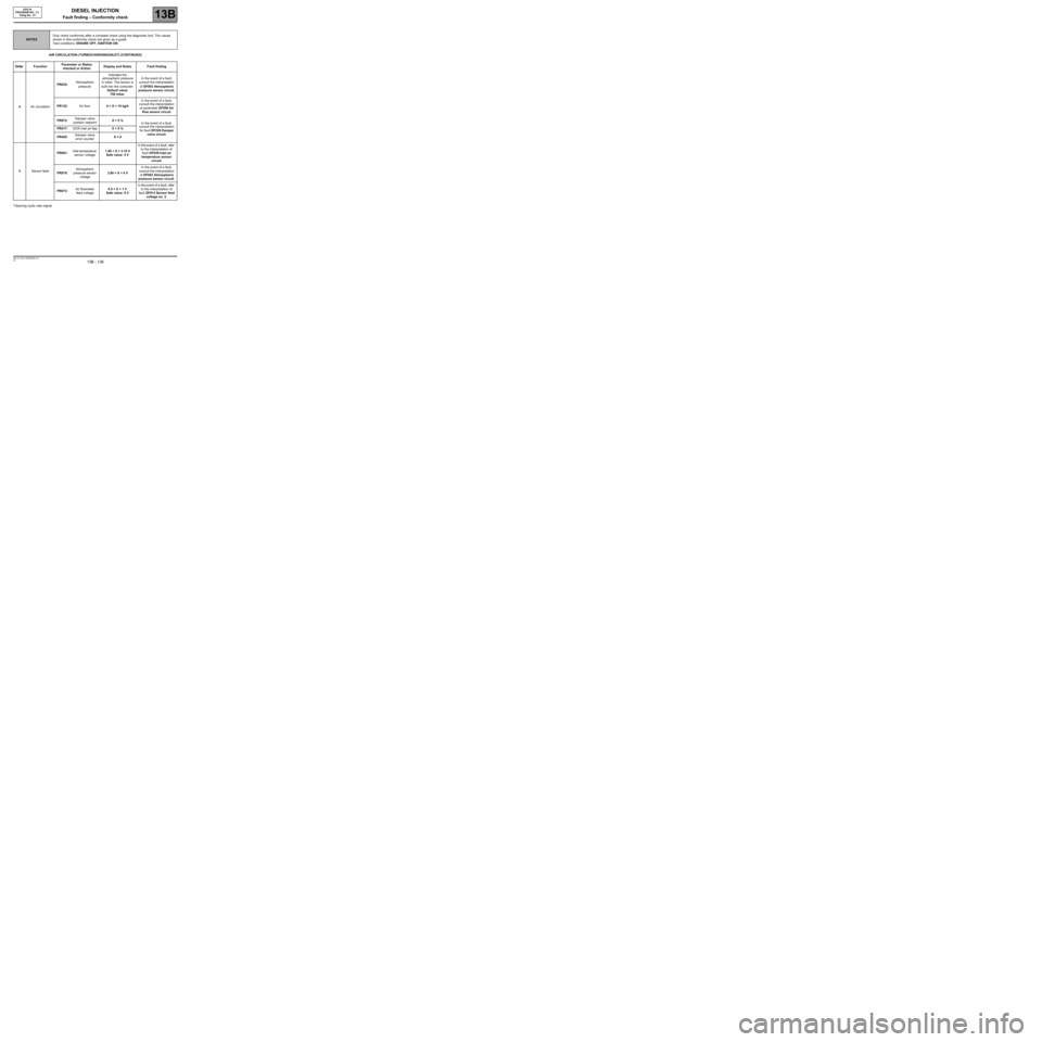
AIR CIRCULATION (TURBOCHARGING/INLET) (CONTINUED)
*Opening cyclic ratio signal
NOTESOnly check conformity after a complete check using the diagnostic tool. The values
shown in this conformity check are given as a guide.
Test conditions: ENGINE OFF, IGNITION ON.
Order FunctionParameter or Status
checked or ActionDisplay and Notes Fault finding
4Air circulationPR035:Atmospheric
pressureIndicates the
atmospheric pressure
in mbar. The sensor is
built into the computer.
Default value:
750 mbar.In the event of a fault,
consult the interpretation
of DF003 Atmospheric
pressure sensor circuit.
PR132:Air flow0 < X < 10 kg/hIn the event of a fault,
consult the interpretation
of parameter DF056 Air
flow sensor circuit.
PR672:Damper valve
position setpointX < 5 %
In the event of a fault,
consult the interpretation
for fault DF226 Damper
valve circuit. PR417:OCR inlet air flapX < 5 %
PR420:Damper valve
error counterX = 0
5Sensor feedPR081:Inlet temperature
sensor voltage1.90 < X < 3.10 V
Safe value: 5 VIn the event of a fault, refer
to the interpretation of
fault DF039 Inlet air
temperature sensor
circuit.
PR079:Atmospheric
pressure sensor
voltage3.80 < X < 4 VIn the event of a fault,
consult the interpretation
of DF003 Atmospheric
pressure sensor circuit.
PR073:Air flowmeter
feed voltage0.5 < X < 1 V
Safe value: 0 VIn the event of a fault, refer
to the interpretation of
fault DF013 Sensor feed
voltage no. 3.
Page 137 of 273
DIESEL INJECTION
Fault finding – Conformity check13B
13B - 137V3 MR-372-J84-13B250$450.mif
EDC16
PROGRAM NO.: C1
Vdiag No.: 51
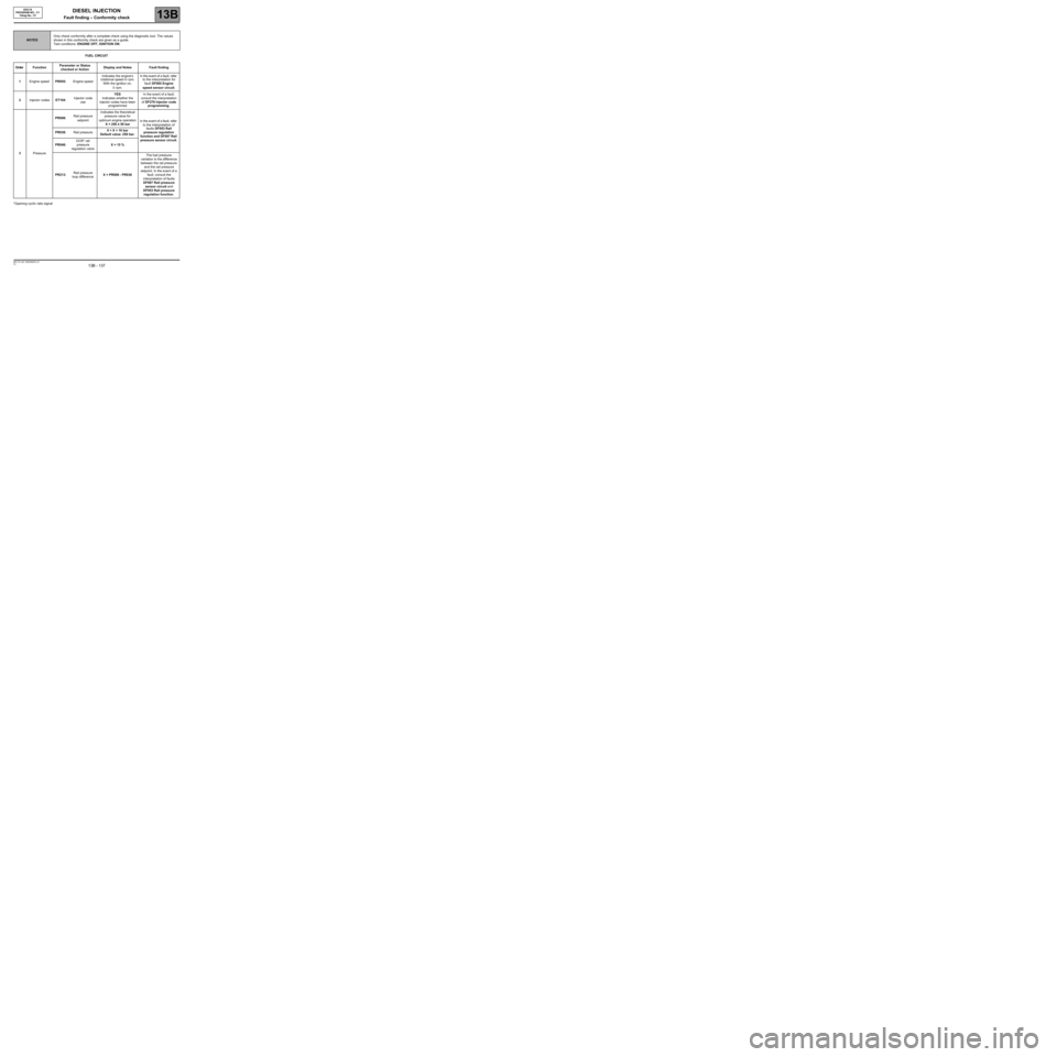
FUEL CIRCUIT
*Opening cyclic ratio signal
NOTESOnly check conformity after a complete check using the diagnostic tool. The values
shown in this conformity check are given as a guide.
Test conditions: ENGINE OFF, IGNITION ON.
Order FunctionParameter or Status
checked or ActionDisplay and Notes Fault finding
1Engine speedPR055:Engine speedIndicates the engine's
rotational speed in rpm.
With the ignition on,
0 rpm.In the event of a fault, refer
to the interpretation for
fault DF005 Engine
speed sensor circuit.
2Injector codesET104:Injector code
useYES
Indicates whether the
injector codes have been
programmedIn the event of a fault,
consult the interpretation
of DF276 Injector code
programming.
3PressurePR008:Rail pressure
setpointIndicates the theoretical
pressure value for
optimum engine operation
X = 250 ± 50 barIn the event of a fault, refer
to the interpretation of
faults DF053 Rail
pressure regulation
function and DF007 Rail
pressure sensor circuit. PR038:Rail pressure0 < X < 10 bar
Default value: 250 bar.
PR048:OCR* rail
pressure
regulation valveX = 15 %
PR213:Rail pressure
loop differenceX = PR008 - PR038The fuel pressure
variation is the difference
between the rail pressure
and the rail pressure
setpoint. In the event of a
fault, consult the
interpretation of faults
DF007 Rail pressure
sensor circuit and
DF053 Rail pressure
regulation function.
Page 138 of 273
DIESEL INJECTION
Fault finding – Conformity check13B
13B - 138V3 MR-372-J84-13B250$450.mif
EDC16
PROGRAM NO.: C1
Vdiag No.: 51
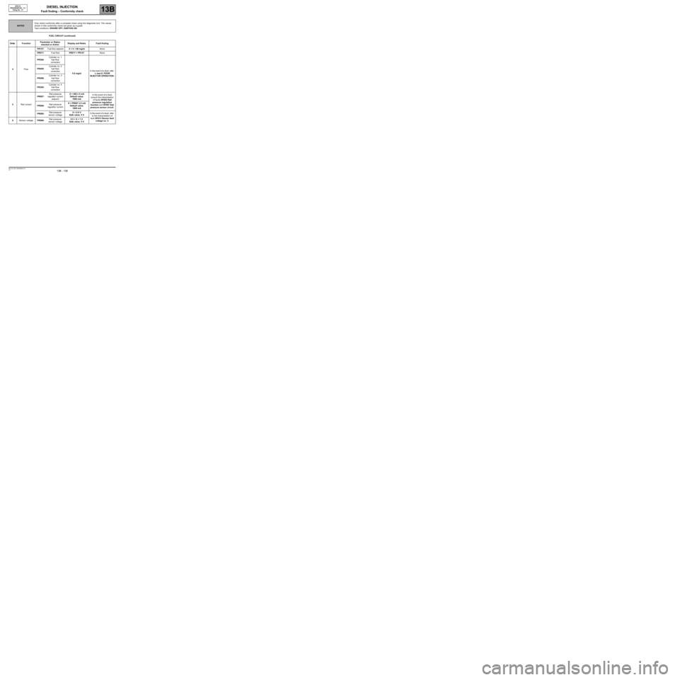
FUEL CIRCUIT (continued)
NOTESOnly check conformity after a complete check using the diagnostic tool. The values
shown in this conformity check are given as a guide.
Test conditions: ENGINE OFF, IGNITION ON.
Order FunctionParameter or Status
checked or ActionDisplay and Notes Fault finding
4FlowPR157:Fuel flow setpoint0 < X < 60 mg/stNone
PR017:Fuel flowPR017 = PR157None
PR364:Cylinder no. 1
fuel flow
correction
0.0 mg/stIn the event of a fault, refer
to test 8: POOR
INJECTOR OPERATION. PR405:Cylinder no. 2
fuel flow
correction
PR406:Cylinder no. 3
fuel flow
correction
PR365:Cylinder no. 4
fuel flow
correction
5Rail currentPR007:Rail pressure
regulator current
setpointX = 400 ± 5 mA
Default value:
1600 mAIn the event of a fault,
consult the interpretation
of faults DF053 Rail
pressure regulation
function and DF007 Rail
pressure sensor circuit. PR006:Rail pressure
regulator currentX = PR007 ± 5 mA
Default value:
1600 mA
PR080:Rail pressure
sensor voltageX = 0.5 V
Safe value: 5 VIn the event of a fault, refer
to the interpretation of
fault DF013 Sensor feed
voltage no. 3. 6Sensor voltagePR080:Rail pressure
sensor voltage0.5 < X < 1 V
Safe value: 5 V
Page 139 of 273
DIESEL INJECTION
Fault finding – Conformity check13B
13B - 139V3 MR-372-J84-13B250$450.mif
EDC16
PROGRAM NO.: C1
Vdiag No.: 51
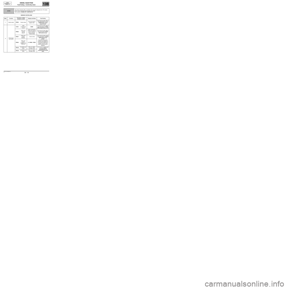
EMISSION CONTROL/OBD
NOTESOnly check conformity after a complete check using the diagnostic tool. The values
shown in this conformity check are given as a guide.
Test conditions: ENGINE OFF, IGNITION ON.
Order FunctionParameter or Status
checked or ActionDisplay and Notes Fault finding
1Engine speedPR055:Engine speedGives the engine's
speed in rpmIn the event of a fault, refer to
the interpretation for fault
DF005 Engine speed
sensor circuit.
2Exhaust gas
recirculationET651:EGR
programming
cut-offNONEIn the event of a fault, refer to
the interpretation of ET651
EGR programming cut-off.
PR005:EGR valve
opening
setpointGives a theoretical
EGR valve opening
value for optimum
engine operation.
- 10 < X < 0 %In the event of a fault, refer to
fault interpretation DF272
EGR control circuit.
PR051:EGR valve
position
feedback- 10 < X < 0 %In the event of a fault, consult
the interpretation of DF118
EGR solenoid valve
control
The EGR valve position
feedback loop difference
must equal the difference
between the EGR valve
position and the position
feedback. PR022:EGR valve
position
feedback loop
differenceX = PR005 - PR051
PR128:First EGR valve
offset10 % < X < 40 %
(average value)In the event of a fault, apply
command SC036
Reinitialisation of
programming and EGR
valve. PR129:Last EGR valve
offset10 % < X < 40 %
(average value)
Page 140 of 273
DIESEL INJECTION
Fault finding – Conformity check13B
13B - 140V3 MR-372-J84-13B250$450.mif
EDC16
PROGRAM NO.: C1
Vdiag No.: 51
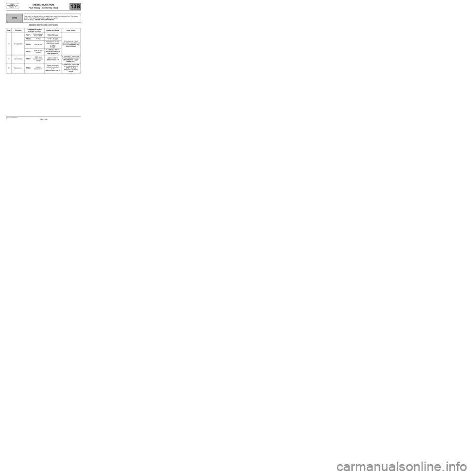
EMISSION CONTROL/OBD (CONTINUED)
NOTESOnly check conformity after a complete check using the diagnostic tool. The values
shown in this conformity check are given as a guide.
Test conditions: ENGINE OFF, IGNITION ON.
Order FunctionParameter or Status
checked or ActionDisplay and Notes Fault finding
3Air regulationPR171:Air flow setpoint
for the EGR750 ± 200 mg/st
In the event of a fault,
consult the interpretation of
parameter DF056 Air flow
sensor circuit. PR132:Air flow0 < X < 10 kg/h
PR146:Inlet air flowIndicates the air flow
entering the engine
in mg/st
0 mg/st
PR131:EGR air flow
variationX = PR146 - PR171
should be close to 0
with ignition on
4Sensor feedPR077:EGR valve
position sensor
voltage0.5 < X < 1.5 V
default value: 0 VIn the event of a fault, refer
to the interpretation of fault
DF012 Sensor supply
voltage no. 2.
5TemperaturePR064:Coolant
temperatureShows the engine
coolant temperature
in ˚C
Default value: 119 ˚CIn the event of a fault, refer
to the interpretation of
DF001 Coolant
temperature sensor
circuit.