charging RENAULT SCENIC 2009 J84 / 2.G Engine And Peripherals EDC16 User Guide
[x] Cancel search | Manufacturer: RENAULT, Model Year: 2009, Model line: SCENIC, Model: RENAULT SCENIC 2009 J84 / 2.GPages: 273
Page 33 of 273
DIESEL INJECTION
Fault finding – Interpretation of faults13B
13B-33V3 MR-372-J84-13B250$315.mif
EDC16
PROGRAM No.: C1
Vdiag No.: 51
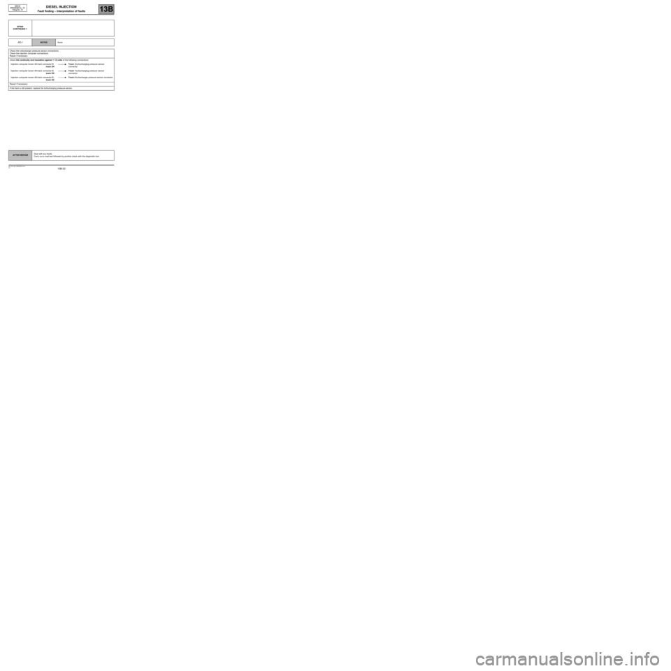
DF004
CONTINUED 1
CC.1
NOTESNone
Check the turbocharger pressure sensor connections.
Check the injection computer connections.
Repair if necessary.
Check the continuity and insulation against + 12 volts of the following connections:
Injection computer brown 48-track connector B,
track G4Track 3 turbocharging pressure sensor
connector
Injection computer brown 48-track connector B,
track D4Track 1 turbocharging pressure sensor
connector
Injection computer brown 48-track connector B,
track K2Track 4 turbocharger pressure sensor connector
Repair if necessary.
If the fault is still present, replace the turbocharging pressure sensor.
AFTER REPAIRDeal with any faults.
Carry out a road test followed by another check with the diagnostic tool.
Page 34 of 273
DIESEL INJECTION
Fault finding – Interpretation of faults13B
13B-34V3 MR-372-J84-13B250$315.mif
EDC16
PROGRAM No.: C1
Vdiag No.: 51
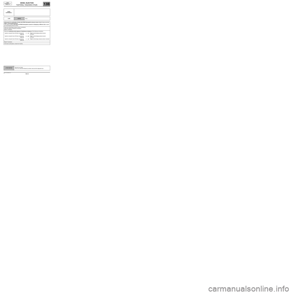
DF004
CONTINUED 2
1.DEF
NOTESNone
In the event of a combination of faults with DF003 Atmospheric pressure sensor circuit, display parameter
PR041 Turbocharging pressure.
If this value is locked at 750 mbar and PR035 Atmospheric pressure is displaying a different value, replace
the turbocharging pressure sensor.
Check the turbocharger pressure sensor connections.
Check the injection computer connections.
Repair if necessary.
Check the continuity and the absence of interference resistance of the following connections:
Injection computer brown 48-track connector B,
track G4Track 3 turbocharging pressure sensor
connector
Injection computer brown 48-track connector B,
track D4Track 1 turbocharging pressure sensor
connector
Injection computer brown 48-track connector B,
track K2Track 4 turbocharger pressure sensor connector
Repair if necessary.
If the fault is still present, contact the Techline.
AFTER REPAIRDeal with any faults.
Carry out a road test followed by another check with the diagnostic tool.
Page 39 of 273
DIESEL INJECTION
Fault finding – Interpretation of faults13B
13B-39V3 MR-372-J84-13B250$315.mif
EDC16
PROGRAM No.: C1
Vdiag No.: 51
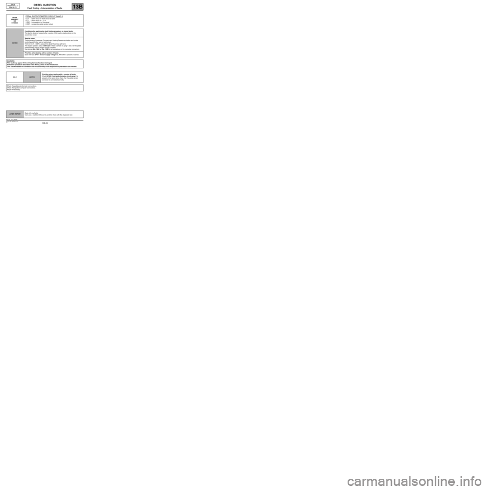
DF008
PRESENT
OR
STOREDPEDAL POTENTIOMETER CIRCUIT GANG 1
CO.0 : Open circuit or short circuit to earth
CC.1 : Short circuit to + 12 V
1.DEF : Inconsistency of the signal
2.DEF : Accelerator pedal sensor locked
NOTESConditions for applying the fault finding procedure to stored faults:
The fault is declared present after a series of full-load/no-load actions on the
accelerator pedal.
Special notes:
Turbocharging, Passenger Compartment Heating Resistor activation and cruise
control/speed limiter are not authorised.
If CO.0, CC.1, 1.DEF is present the level 1 warning light is lit.
The engine speed is set at 1,400 rpm if there is a fault on gang 1 and 2 of the pedal
potentiometer and the engine torque is limited.
Use bornier Ele. 1681 or Ele. 1590 for all operations on the computer connectors.
Priorities when dealing with a number of faults:
Deal with fault DF011 Sensor supply voltage no. 1 first if it is present or stored.
WARNING
This fault may appear if the wiring harness has been damaged.
Follow the procedure described in the Wiring Check in the Introduction.
This check enables the condition and the conformity of the engine wiring harness to be checked.
CO.0
NOTESPriorities when dealing with a number of faults:
If fault DF009 Pedal potentiometer circuit gang 2 is
present at the same time, check that the pedal sensor
connector is connected correctly.
Check the pedal potentiometer connections.
Check the injection computer connections.
Repair if necessary.
AFTER REPAIRDeal with any faults.
Carry out a road test followed by another check with the diagnostic tool.
EDC16_V51_DF008
Page 43 of 273
DIESEL INJECTION
Fault finding – Interpretation of faults13B
13B-43V3 MR-372-J84-13B250$315.mif
EDC16
PROGRAM No.: C1
Vdiag No.: 51
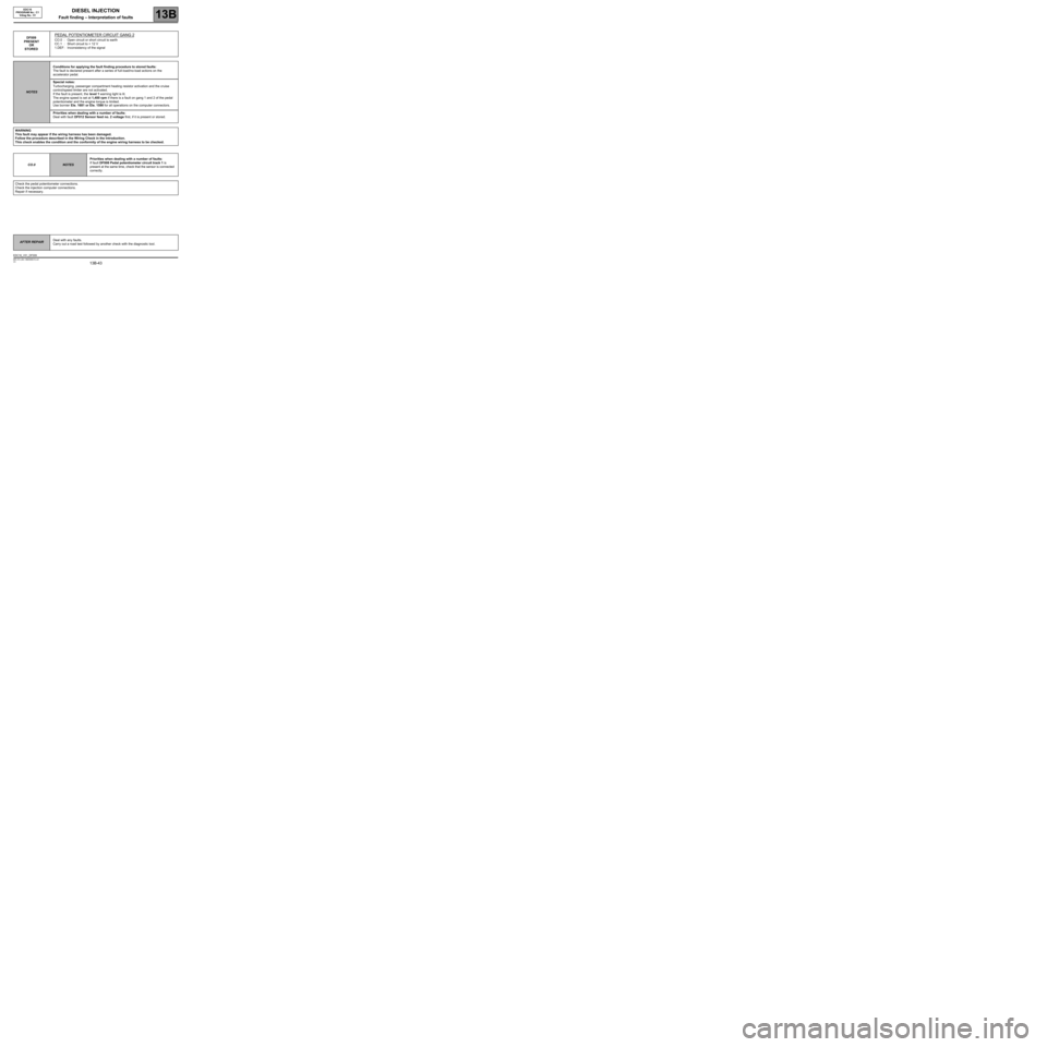
DF009
PRESENT
OR
STOREDPEDAL POTENTIOMETER CIRCUIT GANG 2
CO.0 : Open circuit or short circuit to earth
CC.1 : Short circuit to + 12 V
1.DEF : Inconsistency of the signal
NOTESConditions for applying the fault finding procedure to stored faults:
The fault is declared present after a series of full-load/no-load actions on the
accelerator pedal.
Special notes:
Turbocharging, passenger compartment heating resistor activation and the cruise
control/speed limiter are not activated.
If the fault is present, the level 1 warning light is lit.
The engine speed is set at 1,400 rpm if there is a fault on gang 1 and 2 of the pedal
potentiometer and the engine torque is limited.
Use bornier Ele. 1681 or Ele. 1590 for all operations on the computer connectors.
Priorities when dealing with a number of faults:
Deal with fault DF012 Sensor feed no. 2 voltage first, if it is present or stored.
WARNING
This fault may appear if the wiring harness has been damaged.
Follow the procedure described in the Wiring Check in the Introduction.
This check enables the condition and the conformity of the engine wiring harness to be checked.
CO.0
NOTESPriorities when dealing with a number of faults:
If fault DF008 Pedal potentiometer circuit track 1 is
present at the same time, check that the sensor is connected
correctly.
Check the pedal potentiometer connections.
Check the injection computer connections.
Repair if necessary.
AFTER REPAIRDeal with any faults.
Carry out a road test followed by another check with the diagnostic tool.
EDC16_V51_DF009
Page 46 of 273
DIESEL INJECTION
Fault finding – Interpretation of faults13B
13B-46V3 MR-372-J84-13B250$315.mif
EDC16
PROGRAM No.: C1
Vdiag No.: 51
DF011
PRESENT
OR
STOREDSENSOR SUPPLY VOLTAGE NO. 1
1.DEF : Sensor reference voltage too low
2.DEF : Sensor reference voltage too high
NOTESConditions for applying the fault finding procedure to stored faults:
The fault is declared present after carrying out a road test or after several attempts at
starting the engine.
Special notes:
If the fault is present:
–the cruise control/speed limiter function is inhibited,
–turbocharging is inhibited,
–the engine speed is limited,
–the level 1 warning light is lit,
–the OBD warning light will come on after three consecutive driving cycles (starting
+ 5 seconds + switching off the ignition and waiting 1 minute).
Use bornier Ele. 1681 or Ele. 1590 for any operation on the injection computer
connectors.
WARNING
This fault may appear if the wiring harness has been damaged.
Follow the procedure described in the Wiring Check in the Introduction.
This check enables the condition and the conformity of the engine wiring harness to be checked.
1.DEF
2.DEF
NOTESPriorities when dealing with a number of faults:
If fault DF008 Pedal potentiometer circuit track 1 is
present at the same time, check that the sensor is connected
correctly.
In the event of the simultaneous presence of fault DF004
Turbocharging pressure sensor circuit, check that the
turbocharger pressure sensor circuit connector is connected
correctly.
The sensors connected to supply no. 1 are:
–Turbocharger pressure sensor.
–Accelerator pedal potentiometer sensor, gang 1.
To locate a faulty sensor and/or connection, disconnect one of these sensors then check whether the fault
becomes stored.
If the fault is still present, start the operation again with the other sensor.
(Wait a few seconds after each disconnection so that the computer can carry out the check).
If the fault is stored after a disconnection, replace the faulty sensor or repair its connection.
Clear the faults created by the multiple disconnections.
AFTER REPAIRDeal with any faults.
Carry out a road test followed by another check with the diagnostic tool.
EDC16_V51_DF011
Page 47 of 273

DIESEL INJECTION
Fault finding – Interpretation of faults13B
13B-47V3 MR-372-J84-13B250$315.mif
EDC16
PROGRAM No.: C1
Vdiag No.: 51
DF011
CONTINUED
If the fault is still present when both these sensors have been disconnected:
1. Check the earth insulation of the following connections:
Injection computer brown 48-track connector B,
track G4Track 3 of the turbocharger pressure sensor
Injection computer brown 48-track connector B,
track K2Track 4 of the turbocharger pressure sensor
Injection computer black 32-track connector A,
track G2Track 3 of the accelerator pedal potentiometer
gang 1
Injection computer black 32-track connector A,
track H2Track 4 of the accelerator pedal potentiometer
gang 1
Repair if necessary.
2. Check the insulation from + 12 V of the following connections:
Injection computer brown 48-track connector B,
track K2Track 4 of the turbocharger pressure sensor
Injection computer brown 48-track connector B,
track D4Track 1 of the turbocharger pressure sensor
Injection computer brown 48-track connector B,
track G4Track 3 of the turbocharger pressure sensor
Injection computer black 32-track connector A,
track H3Track 5 of the accelerator pedal potentiometer
gang 1
Injection computer black 32-track connector B,
track H2Track 4 of the accelerator pedal potentiometer
gang 1
Injection computer black 32-track connector B,
track G2Track 3 of the accelerator pedal potentiometer
gang 1
Repair if necessary.
3. Check the insulation between the following connections after disconnecting the sensors and the
injection computer:
–tracks 1 and 3 of the turbocharging pressure sensor connector,
–tracks 3 and 5 of the pedal track 1 sensor connector.
If these checks do not produce the correct results, replace the faulty sensor(s).
If the fault is still present, contact the Techline.
AFTER REPAIRDeal with any faults.
Carry out a road test followed by another check with the diagnostic tool.
Page 84 of 273
DIESEL INJECTION
Fault finding – Interpretation of faults13B
13B-84V3 MR-372-J84-13B250$360.mif
EDC16
PROGRAM No.: C1
Vdiag No.: 51
DF054
PRESENT
OR
STORED
TURBOCHARGING SOLENOID VALVE CONTROL CIRCUIT
CC.1 : Short circuit to + 12 V
CC.0 : Short circuit to earth
CO : Open circuit
1.DEF : Internal electronic fault
2.DEF : Inconsistent signal
3.DEF : Below minimum threshold
4.DEF : Above maximum threshold
5.DEF : Permanent high signal
NOTESConditions for applying the fault finding procedure to stored faults:
The fault is declared present after:
–the engine is started,
–a road test,
–actuator command AC004 Turbocharging solenoid valve.
Special notes:
If the fault is present:
–turbocharging is no longer authorised,
–the EGR function is inhibited,
–the vehicle performance is reduced,
–the level 1 warning light is lit,
–If CC.0 is present, the OBD warning light will come on after three consecutive driving
cycles (starting + 5 seconds + switching off the ignition and waiting for 1 minute).
Use bornier Ele. 1681 or Ele. 1590 for any operation on the injection computer
connectors.
CC.1
4.DEF
5.DEF
NOTESNone
Check the turbocharging solenoid valve connections.
Check the injection computer connections.
Repair if necessary.
Measure the resistance of the turbocharging solenoid valve between tracks 1 and 2:
If the resistance displayed is not 15.4 ± 0.7 Ω at 20˚C, replace the turbocharger solenoid valve.
Check the continuity and insulation from the + 12 V feed of the following connection:
Injection computer grey 32-track connector C,
track E1Track 1 turbocharging solenoid valve
Repair if necessary.
If the fault is still present, replace the turbocharging solenoid valve.
AFTER REPAIRDeal with any faults.
Carry out a road test followed by another check with the diagnostic tool.
EDC16_V51_DF054
Page 85 of 273
DIESEL INJECTION
Fault finding – Interpretation of faults13B
13B-85V3 MR-372-J84-13B250$360.mif
EDC16
PROGRAM No.: C1
Vdiag No.: 51
DF054
CONTINUED 1
CC.0
CO
3.DEF
NOTESNone
Check the turbocharging solenoid valve connections.
Check the injection computer connections.
Repair if necessary.
Measure the resistance of the turbocharging solenoid valve between tracks 1 and 2:
If the resistance displayed is not 15.4 ± 0.7 Ω at 20˚C, replace the turbocharger solenoid valve.
Check the continuity and insulation against earth of the following connections:
Injection computer grey 32-track
connector C, track E1Track 1 turbocharging solenoid valve
UPC PPM1 connector Track 1 Track 2 turbocharger solenoid valve
Repair if necessary.
If the fault is still present, replace the turbocharging solenoid valve.
AFTER REPAIRDeal with any faults.
Carry out a road test followed by another check with the diagnostic tool.
Page 86 of 273
DIESEL INJECTION
Fault finding – Interpretation of faults13B
13B-86V3 MR-372-J84-13B250$360.mif
EDC16
PROGRAM No.: C1
Vdiag No.: 51
*Opening cyclic ratioDF054
CONTINUED 2
1.DEF
2.DEF
NOTESNone
Check the turbocharging solenoid valve connections.
Check the injection computer connections.
Repair if necessary.
Measure the resistance of the turbocharging solenoid valve between tracks 1 and 2:
If the resistance displayed is not 15.4 ± 0.7 Ω at 20˚C, replace the turbocharger solenoid valve.
Check the continuity and insulation against earth of the following connections:
Injection computer grey 32-track
connector C, track E1Track 1 turbocharging solenoid valve
UPC PPM1 connector Track 1 Track 2 Turbocharger solenoid valve
If the fault is still present, check that the computer output is working correctly.
With the turbocharging solenoid valve connected:
Using a voltmeter:
–Connect the negative terminal of the voltmeter to track 1 of the solenoid valve and the negative terminal to
track 2.
–Clear any solenoid valve faults and run command AC004 Turbocharger solenoid valve.
The voltmeter should display ten cycles of two successive voltages: ~ 2.5 V (opening cyclic ratio* of 20%) then
~ 8.75 V (opening cyclic ratio* of 70%).
Or using an oscilloscope (at 5 V range/division and 1 ms/div time base):
–Connect the negative terminal of the oscilloscope to the battery earth and the positive terminal to track 2 of the
solenoid valve.
–Clear any solenoid valve faults and run command AC004 Turbocharging solenoid valve.
The oscilloscope should display a square wave signal with an amplitude of 12.5V (~ battery voltage) at a frequency
of 140 Hz (with an OCR changing successively from ~ 20 to ~ 70%).
–if the measurement is correct, replace the solenoid valve.
–if the measurement does not show any control or continuous voltage, contact the techline.
AFTER REPAIRDeal with any faults.
Carry out a road test followed by another check with the diagnostic tool.
Page 87 of 273
DIESEL INJECTION
Fault finding – Interpretation of faults13B
13B-87V3 MR-372-J84-13B250$360.mif
EDC16
PROGRAM No.: C1
Vdiag No.: 51
DF055
PRESENT
OR
STOREDTURBOCHARGING PRESSURE REGULATION CIRCUIT
1.DEF : Pressure too low
2.DEF : Pressure too high
NOTESConditions for applying the fault finding procedure to a stored fault:
The fault is declared present after the engine is started or following a road test.
Special notes:
If the fault is present:
–turbocharging is no longer authorised,
–the EGR function is inhibited,
–the level 1 warning light is lit.
Use bornier Ele. 1681 or Ele. 1590 for any operation on the injection computer
connectors.
1.DEF
NOTESNone
Check the turbocharger pressure sensor connections.
Check the connections of the turbocharging pressure relief solenoid valve.
Check the injection computer connections.
Repair if necessary.
Check the sealing of the high pressure air circuit:
–disconnected or pierced pipes,
–pressure sensor disconnected or poorly fitted (seal present),
–intercooler pierced (to check the intercooler: with the vehicle stationary, stabilise the engine speed between
3,500 and 4,000 rpm and check that there are no leaks).
Check the conformity of the turbocharger pressure signal and apply test 9 Air line at the turbocharger, then test
5 Turbocharger control solenoid valve check and test 6 Turbocharger.
AFTER REPAIRDeal with any faults.
Carry out a road test followed by another check with the diagnostic tool.
EDC16_V51_DF055