df053 RENAULT SCENIC 2009 J84 / 2.G Engine And Peripherals EDC16 User Guide
[x] Cancel search | Manufacturer: RENAULT, Model Year: 2009, Model line: SCENIC, Model: RENAULT SCENIC 2009 J84 / 2.GPages: 273
Page 224 of 273

DIESEL INJECTION
Fault finding – Fault Finding Chart13B
13B -224V3 MR-372-J84-13B250$855.mif
EDC16
PROGRAM No.: C1
Vdiag No.: 51
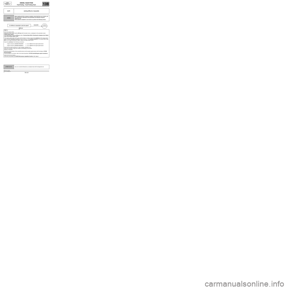
ALP2 starting difficult or impossible
NOTESBefore dealing with this customer complaint, check that there are no faults, and
the conformity (or otherwise) of the parameters and statuses using the
diagnostic tool.
If the customer complaint is not ironed out, perform the following checks:
Is it difficult or impossible to start the engine?impossible(Go to
continued 2)
difficult
PART A:
Check the engine earths.
Ensure that engine speed reaches 250 rpm with the starter motor, as displayed on the parameter screen
(PR055 Engine speed).
If the engine speed is less than 250 rpm, refer to Technical Note 6014A, Checking the charging circuit, Starter
motor fault finding, Starter motor.
If the engine speed under CLIP is zero and the engine is running, measure the resistance of the engine speed
sensor between terminals A and B of its black connector. If the winding resistance is not between 510 Ω and
850 Ω at an engine temperature of 20˚C, replace the engine speed sensor.
Check the continuity of the following connections:
–engine computer, connector B track D1 track A of the engine speed sensor
–engine computer, connector B track C1 track B of the engine speed sensor
Check that the engine earthing is in order (oxidation, tightness, etc.).
Check the mounting, air gap and condition (overheating) of the sensor.
Replace if necessary.
Check the synchronisation of the camshaft sensors and the engine speed sensors with the display of ET238
Synchronisation.
If synchronisation is not active, refer to the checks described in DF195 Camshaft/engine speed consistency.
check the fuel circuit sealing.
If the fault is still present, see DF053 Rail pressure regulation function 2.def, stage 4.
AFTER REPAIRcarry out a road test followed by a complete check with the diagnostic tool.
EDC16_V51_ALP2
Page 229 of 273

DIESEL INJECTION
Fault finding – Fault Finding Chart13B
13B -229V3 MR-372-J84-13B250$855.mif
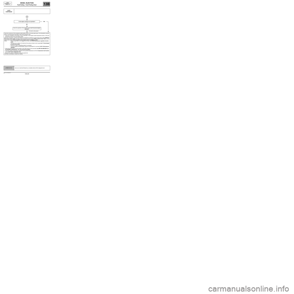
ALP4
CONTINUED
Is the engine running on all cylinders?
NO
Check the operation of the injectors: apply test 8 Incorrect injector
operation.
If the fault is still present
Check the conformity of the accelerator pedal position sensor, the brake pedal sensor, the atmospheric pressure
sensor, the exhaust gas recirculation valve and the damper valve.
–Check the consistency of the signal: of the air flowmeter, of the engine coolant temperature sensor, of the fuel
temperature sensor and of the engine speed.
Check the connections, continuity and absence of interference resistance on the air flow sensor (apply DF056 Air
flow sensor circuit, 2.def), the engine coolant temperature sensor (apply DF001 Coolant circuit, 1.def), and the
engine speed (apply DF195 Camshaft sensor/engine speed consistency, 2.def).
Check: – That the diesel filter is not clogged (for the test, see DF053 Rail pressure regulation function
2.def).
–That there are no leaks on the high and low pressure diesel circuits: apply test 3 Turbocharged
air inlet circuit check.
–That the oil vapour rebreathing system is connected.
–The flow regulator (blocked/seized, apply the interpretation for command: AC011 Rail pressure
regulator).
–Check the timing setting (and the position of the high pressure pump sprocket) (see MR 364 (MEGANE II) or
370 (SCENIC II), Mechanical, 11A, Top and front of engine).
–Check the cylinder compressions (balance of the cylinder compressions with the Compression test function
on the CLIP Technic diagnostic tool).
–Measure the engine compressions using the special tool.
If the fault is still present, contact the Techline.YES
EDC16
PROGRAM No.: C1
Vdiag No.: 51
AFTER REPAIRcarry out a road test followed by a complete check with the diagnostic tool.