air condition RENAULT SCENIC 2010 J95 / 3.G Petrol Injection S3000 Injection Workshop Manual
[x] Cancel search | Manufacturer: RENAULT, Model Year: 2010, Model line: SCENIC, Model: RENAULT SCENIC 2010 J95 / 3.GPages: 230, PDF Size: 0.92 MB
Page 148 of 230

PETROL INJECTION
Fault finding - Conformity check
17B
17B-148
PETROL INJECTION
Fault finding - Conformity check
17B
17B-148V9 MR-372-J84-17B050$517.mif
S3000 Injection
Program No.: AD
Vdiag No.: 4C / 54
SUB-FUNCTION: FUEL CIRCUIT (continued 1):
OCR: Opening Cycle Ratio
NOTESOnly perform this conformity check after a complete check with the diagnostic tool.
The values shown in this conformity check are given as a guide.
Application conditions: Engine warm, idling.
Order FunctionParameter or Status
Checked or ActionDisplay and notes Fault finding
5
Motorised
throttlePR090:Idle speed
regulation
programming
valuePR090≈ 0%
PR090, an adaptive built-in
action, is a stored parameter
designed to program variation
and engine ageing for the idle
speed regulator. These are
programmed only when the
engine is idling and warm, and
no electrical consumers
(electrical windscreen, air
conditioning, GMV, power
steering) have been selected.
Therefore it adjusts slowly.WITHOUT
6 PR091:Theoretical idle
speed regulation
OCR5%
regulation are met, the idle
regulator continually
repositions the motorised
throttle to keep the engine
speed at the idling speed
setting. The motorised throttle
opening ratio required to adhere
to the engine speed setpoint is
then given by parameter PR091.
Page 160 of 230

PETROL INJECTION
Fault finding - Conformity check
17B
17B-160
PETROL INJECTION
Fault finding - Conformity check
17B
17B-160V9 MR-372-J84-17B050$517.mif
S3000 Injection
Program No.: AD
Vdiag No.: 4C / 54
COLD LOOP SUB-FUNCTION:
NOTESOnly perform this conformity check after a complete check with the diagnostic tool.
The values shown in this conformity check are given as a guide.
Application conditions: Engine warm, idling.
Order FunctionParameter or Status
Checked or ActionDisplay and notes Fault finding
1
Air conditioningET079:Air conditioning
presentShows whether or not
the vehicle is equipped
with air conditioning.
YES: Air conditioning is
detected by the injection
computer.
NO: Air conditioning is not
detected by the injection
computer.If inconsistent with
the vehicle
equipment, carry out
a multiplex network
test and apply the
relevant procedure.
2 ET088:Compressor
actuation
requestThe injection requests
the UCH (via the
multiplex network) to
start the compressor.
ACTIVE: The multiplex
network must not be faulty
on the automatic gearbox,
fuse and relay box or UCH
systems. The UCH must
send a compressor
starting request to the
injection. The coolant
pressure sensor must not
be defective. Satisfactory
engine operating
conditions (coolant
temperature, engine load,
etc.).
INACTIVE: One of the
above conditions has not
been met.WITHOUT
3 ET004:Air conditioning
authorisationYES
NO
Page 161 of 230

PETROL INJECTION
Fault finding - Conformity check
17B
17B-161
PETROL INJECTION
Fault finding - Conformity check
17B
17B-161V9 MR-372-J84-17B050$517.mif
S3000 Injection
Program No.: AD
Vdiag No.: 4C / 54
SUB-FUNCTION: COLD LOOP (continued 1):
NOTESOnly perform this conformity check after a complete check with the diagnostic tool.
The values shown in this conformity check are given as a guide.
Application conditions: Engine warm, idling.
Order FunctionParameter or Status
Checked or ActionDisplay and notes Fault finding
4 ET023:Fast idle speed
requestUCH requests the
injection system to
increase the idling
speed.
INACTIVE: The UCH
has not formulated a
request.
ACTIVE: The UCH has
formulated a requestIf ET023 is
inconsistent, run a
multiplex network
test using the
diagnostic tool; then
if the test is in order,
consult the UCH.
5 Engine speed PR055:Engine speedShows the speed of
rotation in rpm.
700 rpm < PR055
< 800 rpmIn the event of a fault,
apply the
interpretation for
DF154 Flywheel
signal sensor
circuit.
6
Air conditioningPR037:Refrigerant
pressure2Bar
Default value: 0 Bar.If 1.DEF, apply
interpretation of
PR037 Coolant
pressure.
7 ET674:Refrigerant
pressure statusCORRECT
TOO LOW
8PR125:Power used by the
AC compressor0 < PR125 < 300 W WITHOUT
9Coolant
temperaturePR064:Coolant
temperature- 40°C < PR064
< 120°C
Safe value: - 39°CIn the event of a fault,
apply the
interpretation of
DF001 Coolant
temperature sensor
circuit.
10 Vehicle speed PR089:Vehicle speedGives the vehicle
speed in mph (km/h).
This parameter is
sent to the injection
by the ABS computer
via the multiplex
network.In the event of a fault,
apply the
interpretation of
DF091 Vehicle speed
signal.
Page 166 of 230

PETROL INJECTION
Fault finding - Conformity check
17B
17B-166
PETROL INJECTION
Fault finding - Conformity check
17B
17B-166V9 MR-372-J84-17B050$517.mif
S3000 Injection
Program No.: AD
Vdiag No.: 4C / 54
STARTING SUB-FUNCTION:
NOTESOnly perform this conformity check after a complete check with the diagnostic tool.
The values shown in this conformity check are given as a guide.
Application conditions: Engine warm, idling.
Order FunctionParameter or Status
Checked or ActionDisplay and notes Fault finding
1StartingET076:StartingAUTHORISEDAuthorisation to start is
given once the petrol
pump is pressurised
and if the motorised
throttle has emerged
from the stop and limp-
home position
programming phase.
2Actuator relay
controlET048:Actuator relay
controlACTIVEIf INACTIVE, apply the
interpretation of DF084
Actuator relay control
circuit.
3 Battery voltage PR074:Battery voltage11 V < PR074 < 15 VIn the event of a fault,
apply the interpretation of
DF046 Battery voltage.
4 Impact signal ET077:Impact
detectedNOIn the event of a fault,
run a multiplex network
test using the
diagnostic tool; then, if
the test is OK, carry out
fault finding on the
airbag computer.
Page 168 of 230

PETROL INJECTION
Fault finding - Status summary table
17B
17B - 168
PETROL INJECTION
Fault finding - Status summary table
17B
17B - 168V9 MR-372-J84-17B050$564.mif
S3000 Injection
Program No.: AD
Vdiag No.: 4C / 54PETROL INJECTION
Fault finding - Status summary table
Tool status Diagnostic tool title
ET001+ After ignition computer feed
ET003Engine immobiliser
ET004Air conditioning authorisation
ET006Code programmed
ET021High speed fan assembly request
ET022Low speed fan assembly request
ET023Fast idle speed request
ET042Cruise control/speed limiter
ET047Fuel pump control circuit
ET048Actuator relay control
ET050Canister bleed control
ET051Throttle stop programming
ET052Upstream O
2 sensor heating
ET053Downstream O
2 sensor heating
ET054Idle speed regulation
ET056Richness double loop
ET057Misfiring on cylinder 1
ET058Misfiring on cylinder 2
ET059Misfiring on cylinder 3
ET060Misfiring on cylinder 4
ET061Cylinder 1 recognition
ET062Flywheel signal
ET063Park/Neutral position
ET064Level 1 injection fault
ET065Level 2 Injection fault
ET066LPG fault
ET067LPG ready
ET068LPG tank empty
ET071Transition from petrol mode to LPG mode
ET072Transition from LPG mode to petrol mode
ET073Conditions for switching to LPG mode
ET075Pedal released and throttle closed
MR-372-J84-17B050$564.mif
Page 169 of 230

PETROL INJECTION
Fault finding - Status summary table
17B
17B - 169
PETROL INJECTION
Fault finding - Status summary table
17B
17B - 169V9 MR-372-J84-17B050$564.mif
S3000 Injection
Program No.: AD
Vdiag No.: 4C / 54
Tool status Diagnostic tool title
ET076Starting
ET077Impact detected
ET079Air conditioning present
ET081Accelerator pedal position
ET082Motorised throttle position
ET083Camshaft dephaser in defect mode
ET086Camshaft dephaser control
ET088Compressor actuation request
ET089Flywheel target programming
ET111RCH number set
ET112RCH cut-off
ET300Richness regulation
ET340Request by automatic transmission to light up the OBD warning light
ET405Clutch pedal switch
ET415Deactivation of cruise control/speed limiter
ET561Operating mode
ET564Type 1 defect mode
ET565Type 2 defect mode
ET566Type 3 defect mode
ET567Type 4 defect mode
ET568Type 5 defect mode
ET569Type 6 defect mode
ET581Petrol combustion misfiring fault finding
ET582LPG combustion misfire fault finding
ET583LPG cylinder 1 combustion misfire
ET584LPG cylinder 2 combustion misfire
ET585LPG cylinder 3 combustion misfire
ET586LPG cylinder 4 combustion misfire
ET617Upstream oxygen sensor OBD fault finding
ET619Fuel circuit OBD fault finding
ET674Refrigerant pressure
ET703Cruise control/speed limiter buttons
ET704Brake switch no. 1
ET705Brake switch no. 2
Page 174 of 230

PETROL INJECTION
Fault finding - Interpretation of statuses
17B
17B - 174
PETROL INJECTION
Fault finding - Interpretation of statuses
17B
17B - 174V9 MR-372-J84-17B050$611.mif
S3000 Injection
Program No.: AD
Vdiag No.: 4C / 54
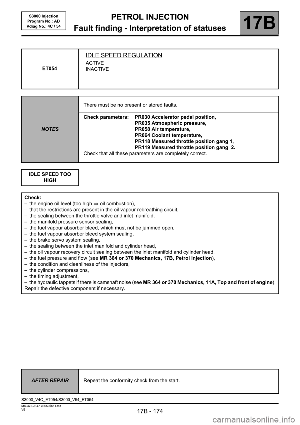
ET054
IDLE SPEED REGULATION
ACTIVE
INACTIVE
NOTESThere must be no present or stored faults.
Check parameters: PR030 Accelerator pedal position,
PR035 Atmospheric pressure,
PR058 Air temperature,
PR064 Coolant temperature,
PR118 Measured throttle position gang 1,
PR119 Measured throttle position gang 2.
Check that all these parameters are completely correct.
IDLE SPEED TOO
HIGH
Check:
– the engine oil level (too high ⇒ oil combustion),
– that the restrictions are present in the oil vapour rebreathing circuit,
– the sealing between the throttle valve and inlet manifold,
– the manifold pressure sensor sealing,
– the fuel vapour absorber bleed, which must not be jammed open,
– the fuel vapour absorber bleed system sealing,
– the brake servo system sealing,
– the sealing between the inlet manifold and cylinder head,
– the oil vapour recovery circuit sealing between the inlet manifold and cylinder head,
– the fuel pressure and flow (see MR 364 or 370 Mechanics, 17B, Petrol injection),
– the condition and cleanliness of the injectors,
– the cylinder compressions,
– the timing adjustment,
– the hydraulic tappets if there is camshaft noise (see MR 364 or 370 Mechanics, 11A, Top and front of engine).
Repair the defective component if necessary.
AFTER REPAIRRepeat the conformity check from the start.
S3000_V4C_ET054/S3000_V54_ET054
Page 175 of 230

PETROL INJECTION
Fault finding - Interpretation of statuses
17B
17B - 175
PETROL INJECTION
Fault finding - Interpretation of statuses
17B
17B - 175V9 MR-372-J84-17B050$611.mif
S3000 Injection
Program No.: AD
Vdiag No.: 4C / 54
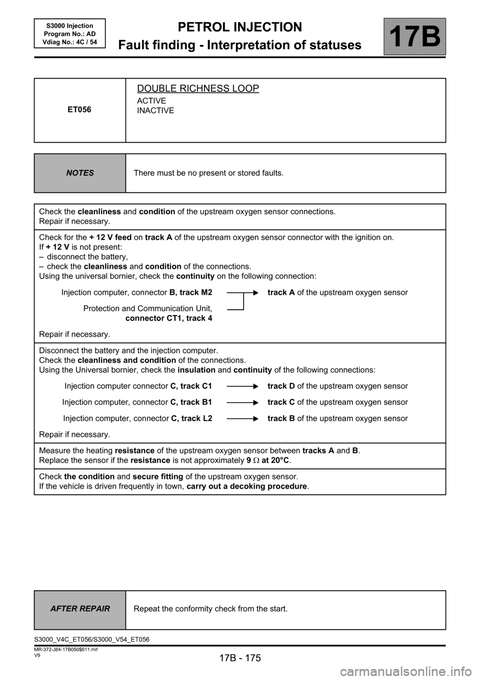
ET056
DOUBLE RICHNESS LOOP
ACTIVE
INACTIVE
NOTESThere must be no present or stored faults.
Check the cleanliness and condition of the upstream oxygen sensor connections.
Repair if necessary.
Check for the + 12 V feed on track A of the upstream oxygen sensor connector with the ignition on.
If +12V is not present:
– disconnect the battery,
– check the cleanliness and condition of the connections.
Using the universal bornier, check the continuity on the following connection:
Injection computer, connectorB, track M2 track A of the upstream oxygen sensor
Protection and Communication Unit,
connector CT1, track 4
Repair if necessary.
Disconnect the battery and the injection computer.
Check the cleanliness and condition of the connections.
Using the Universal bornier, check the insulation and continuity of the following connections:
Injection computer connectorC, track C1 track D of the upstream oxygen sensor
Injection computer, connectorC, track B1 track C of the upstream oxygen sensor
Injection computer, connectorC, track L2 track B of the upstream oxygen sensor
Repair if necessary.
Measure the heating resistance of the upstream oxygen sensor between tracks A and B.
Replace the sensor if the resistance is not approximately 9Ω at 20°C.
Check the condition and secure fitting of the upstream oxygen sensor.
If the vehicle is driven frequently in town, carry out a decoking procedure.
AFTER REPAIRRepeat the conformity check from the start.
S3000_V4C_ET056/S3000_V54_ET056
Page 176 of 230

PETROL INJECTION
Fault finding - Interpretation of statuses
17B
17B - 176
PETROL INJECTION
Fault finding - Interpretation of statuses
17B
17B - 176V9 MR-372-J84-17B050$611.mif
S3000 Injection
Program No.: AD
Vdiag No.: 4C / 54
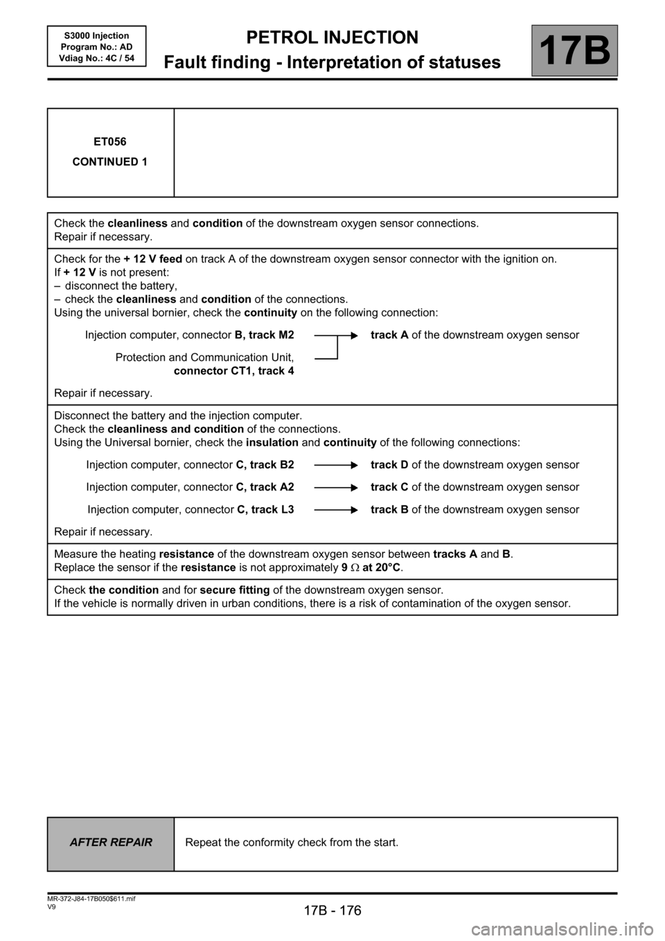
ET056
CONTINUED 1
Check the cleanliness and condition of the downstream oxygen sensor connections.
Repair if necessary.
Check for the + 12 V feed on track A of the downstream oxygen sensor connector with the ignition on.
If +12V is not present:
– disconnect the battery,
– check the cleanliness and condition of the connections.
Using the universal bornier, check the continuity on the following connection:
Injection computer, connectorB, track M2 track A of the downstream oxygen sensor
Protection and Communication Unit,
connector CT1, track 4
Repair if necessary.
Disconnect the battery and the injection computer.
Check the cleanliness and condition of the connections.
Using the Universal bornier, check the insulation and continuity of the following connections:
Injection computer, connectorC, track B2 track D of the downstream oxygen sensor
Injection computer, connectorC, track A2 track C of the downstream oxygen sensor
Injection computer, connectorC, track L3 track B of the downstream oxygen sensor
Repair if necessary.
Measure the heating resistance of the downstream oxygen sensor between tracks A and B.
Replace the sensor if the resistance is not approximately 9Ω at 20°C.
Check the condition and for secure fitting of the downstream oxygen sensor.
If the vehicle is normally driven in urban conditions, there is a risk of contamination of the oxygen sensor.
AFTER REPAIRRepeat the conformity check from the start.
Page 177 of 230

PETROL INJECTION
Fault finding - Interpretation of statuses
17B
17B - 177
PETROL INJECTION
Fault finding - Interpretation of statuses
17B
17B - 177V9 MR-372-J84-17B050$611.mif
S3000 Injection
Program No.: AD
Vdiag No.: 4C / 54
ET056
CONTINUED 2
Check:
– the condition of the air filter,
– that the air inlet circuit is not blocked,
– the condition and conformity of the spark plugs,
– the sealing between the throttle valve and inlet manifold,
– the manifold pressure sensor sealing,
– the fuel vapour absorber bleed, which must not be jammed open,
– the fuel vapour absorber bleed system sealing,
– the brake servo system sealing,
– the cylinder head oil vapour recovery system sealing,
– the sealing between the inlet manifold and cylinder head,
– the exhaust pipe sealing between the cylinder head and catalytic converter.
– the fuel flow rate and pressure.
If the idle speed is not stable, check:
– the timing adjustment,
– the hydraulic tappets if there is camshaft noise (see MR 364 or 370 Mechanics, 11A, Top and front of engine),
– the cylinder compressions.
Drive the vehicle to check the repair.
Repair the defective components.
AFTER REPAIRRepeat the conformity check from the start.