warning RENAULT SCENIC 2010 J95 / 3.G Petrol Injection S3000 Injection Owner's Guide
[x] Cancel search | Manufacturer: RENAULT, Model Year: 2010, Model line: SCENIC, Model: RENAULT SCENIC 2010 J95 / 3.GPages: 230, PDF Size: 0.92 MB
Page 72 of 230

PETROL INJECTION
Fault finding - Interpretation of faults
17B
17B-72
PETROL INJECTION
Fault finding - Interpretation of faults
17B
17B-72V9 MR-372-J84-17B050$376.mif
S3000 Injection
Program No.: AD
Vdiag No.: 4C / 54
DF091
PRESENT
OR
STOREDVEHICLE SPEED SIGNAL
1.DEF: Multiplex network
2.DEF: Non-compliance with emission control standards
NOTESConditions for applying the fault finding procedure to stored faults:
The fault is declared present with the engine running.
Special note:
–OBD warning light illuminated.
Run a multiplex network test (see88B, Multiplexing).
Disconnect the battery and the injection computer.
Check the cleanliness and condition of the battery and the injection computer connections.
Repair if necessary.
If the fault is still present, carry out fault finding on the ABS - ESP system (see38C, Anti-lock braking system).
AFTER REPAIRFollow the instructions to confirm repair.
Deal with any other faults.
Clear the stored faults.
S3000_V4C_DF091/S3000_V54_DF091
Page 73 of 230
PETROL INJECTION
Fault finding - Interpretation of faults
17B
17B-73
PETROL INJECTION
Fault finding - Interpretation of faults
17B
17B-73V9 MR-372-J84-17B050$376.mif
S3000 Injection
Program No.: AD
Vdiag No.: 4C / 54
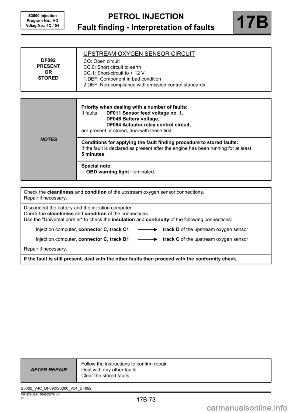
DF092
PRESENT
OR
STORED
UPSTREAM OXYGEN SENSOR CIRCUIT
CO: Open circuit
CC.0: Short circuit to earth
CC.1: Short-circuit to + 12 V
1.DEF: Component in bad condition
2.DEF: Non-compliance with emission control standards
NOTESPriority when dealing with a number of faults:
If faults DF011 Sensor feed voltage no. 1,
DF046 Battery voltage,
DF084 Actuator relay control circuit,
are present or stored, deal with these first.
Conditions for applying the fault finding procedure to stored faults:
If the fault is declared as present after the engine has been running for at least
5 minutes.
Special note:
–OBD warning light illuminated.
Check the cleanliness and condition of the upstream oxygen sensor connections.
Repair if necessary.
Disconnect the battery and the injection computer.
Check the cleanliness and condition of the connections.
Use the "Universal bornier" to check the insulation and continuity of the following connections:
Injection computer, connector C, track C1 track D of the upstream oxygen sensor
Injection computer, connector C, track B1 track C of the upstream oxygen sensor
Repair if necessary.
If the fault is still present, deal with the other faults then proceed with the conformity check.
AFTER REPAIRFollow the instructions to confirm repair.
Deal with any other faults.
Clear the stored faults.
S3000_V4C_DF092/S3000_V54_DF092
Page 74 of 230
PETROL INJECTION
Fault finding - Interpretation of faults
17B
17B-74
PETROL INJECTION
Fault finding - Interpretation of faults
17B
17B-74V9 MR-372-J84-17B050$376.mif
S3000 Injection
Program No.: AD
Vdiag No.: 4C / 54
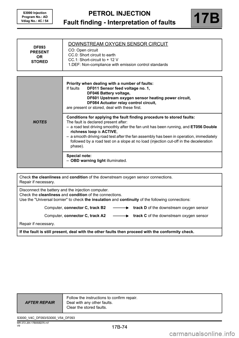
DF093
PRESENT
OR
STOREDDOWNSTREAM OXYGEN SENSOR CIRCUIT
CO: Open circuit
CC.0: Short circuit to earth
CC.1: Short-circuit to + 12 V
1.DEF: Non-compliance with emission control standards
NOTESPriority when dealing with a number of faults:
If faults DF011 Sensor feed voltage no. 1,
DF046 Battery voltage,
DF601 Upstream oxygen sensor heating power circuit,
DF084 Actuator relay control circuit,
are present or stored, deal with these first.
Conditions for applying the fault finding procedure to stored faults:
The fault is declared present after:
– a road test driving smoothly after the fan unit has been running, and ET056 Double
richness loop is ACTIVE,
– a smooth driving road test after the fan assembly has been in operation, immediately
followed by a road test on a slope at no load (injection cut-off in the deceleration
phase).
Special note:
–OBD warning light illuminated.
Check the cleanliness and condition of the downstream oxygen sensor connections.
Repair if necessary.
Disconnect the battery and the injection computer.
Check the cleanliness and condition of the connections.
Use the "Universal bornier" to check the insulation and continuity of the following connections:
Computer, connector C, track B2 track D of the downstream oxygen sensor
Computer, connector C, track A2 track C of the downstream oxygen sensor
Repair if necessary.
If the fault is still present, deal with the other faults then proceed with the conformity check.
AFTER REPAIRFollow the instructions to confirm repair.
Deal with any other faults.
Clear the stored faults.
S3000_V4C_DF093/S3000_V54_DF093
Page 75 of 230
PETROL INJECTION
Fault finding - Interpretation of faults
17B
17B-75
PETROL INJECTION
Fault finding - Interpretation of faults
17B
17B-75V9 MR-372-J84-17B050$376.mif
S3000 Injection
Program No.: AD
Vdiag No.: 4C / 54
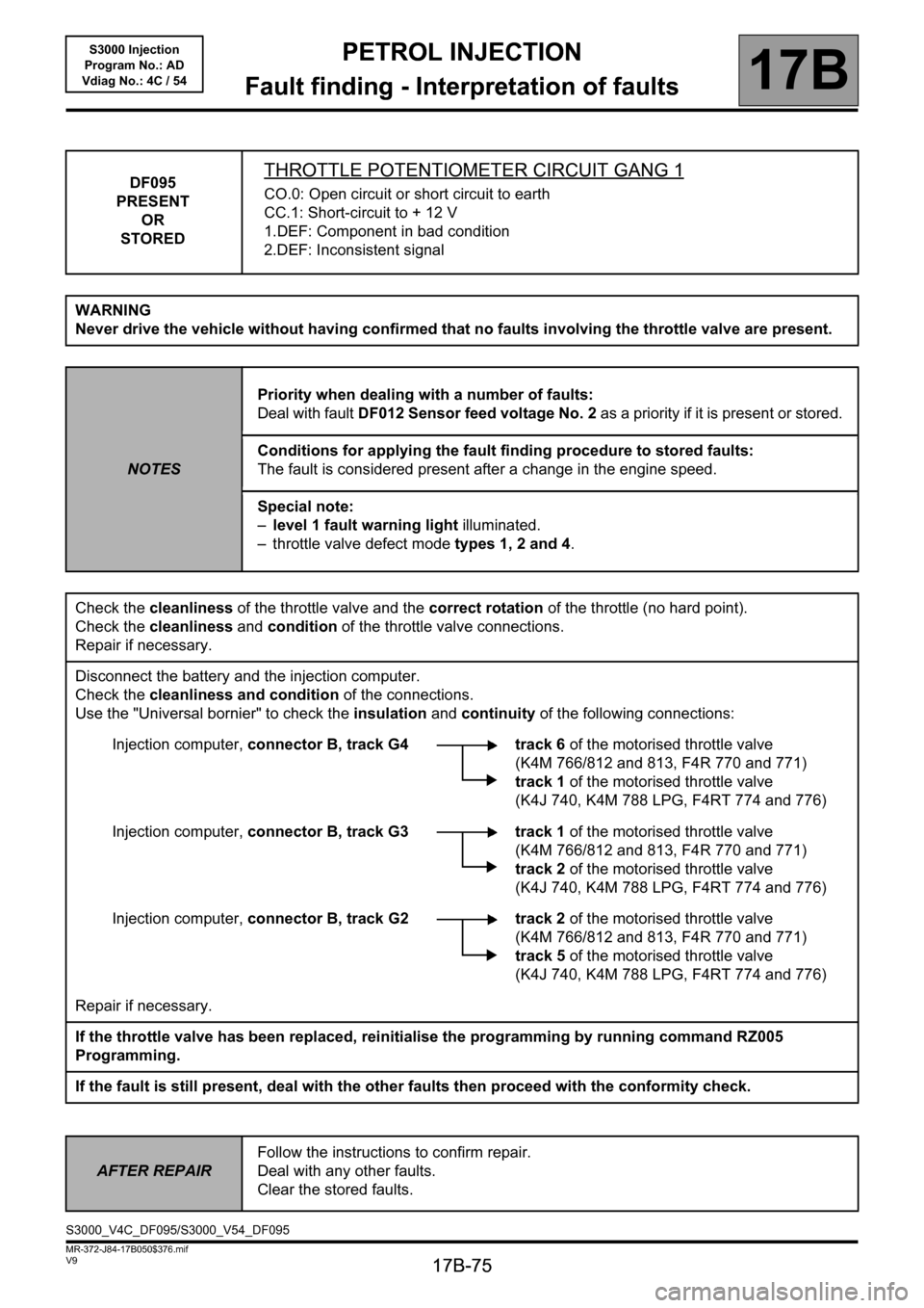
DF095
PRESENT
OR
STOREDTHROTTLE POTENTIOMETER CIRCUIT GANG 1
CO.0: Open circuit or short circuit to earth
CC.1: Short-circuit to + 12 V
1.DEF: Component in bad condition
2.DEF: Inconsistent signal
WARNING
Never drive the vehicle without having confirmed that no faults involving the throttle valve are present.
NOTESPriority when dealing with a number of faults:
Deal with fault DF012 Sensor feed voltage No. 2 as a priority if it is present or stored.
Conditions for applying the fault finding procedure to stored faults:
The fault is considered present after a change in the engine speed.
Special note:
–level 1 fault warning light illuminated.
– throttle valve defect mode types 1, 2 and 4.
Check the cleanliness of the throttle valve and the correct rotation of the throttle (no hard point).
Check the cleanliness and condition of the throttle valve connections.
Repair if necessary.
Disconnect the battery and the injection computer.
Check the cleanliness and condition of the connections.
Use the "Universal bornier" to check the insulation and continuity of the following connections:
Injection computer, connector B, track G4 track 6 of the motorised throttle valve
(K4M 766/812 and 813, F4R 770 and 771)
track 1 of the motorised throttle valve
(K4J 740, K4M 788 LPG, F4RT 774 and 776)
Injection computer, connector B, track G3 track 1 of the motorised throttle valve
(K4M 766/812 and 813, F4R 770 and 771)
track 2 of the motorised throttle valve
(K4J 740, K4M 788 LPG, F4RT 774 and 776)
Injection computer, connector B, track G2 track 2 of the motorised throttle valve
(K4M 766/812 and 813, F4R 770 and 771)
track 5 of the motorised throttle valve
(K4J 740, K4M 788 LPG, F4RT 774 and 776)
Repair if necessary.
If the throttle valve has been replaced, reinitialise the programming by running command RZ005
Programming.
If the fault is still present, deal with the other faults then proceed with the conformity check.
AFTER REPAIRFollow the instructions to confirm repair.
Deal with any other faults.
Clear the stored faults.
S3000_V4C_DF095/S3000_V54_DF095
Page 76 of 230
PETROL INJECTION
Fault finding - Interpretation of faults
17B
17B-76
PETROL INJECTION
Fault finding - Interpretation of faults
17B
17B-76V9 MR-372-J84-17B050$376.mif
S3000 Injection
Program No.: AD
Vdiag No.: 4C / 54
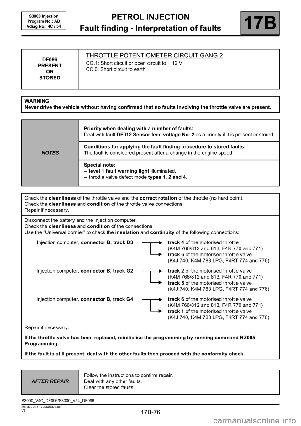
DF096
PRESENT
OR
STOREDTHROTTLE POTENTIOMETER CIRCUIT GANG 2
CO.1: Short circuit or open circuit to + 12 V
CC.0: Short circuit to earth
WARNING
Never drive the vehicle without having confirmed that no faults involving the throttle valve are present.
NOTESPriority when dealing with a number of faults:
Deal with fault DF012 Sensor feed voltage No. 2 as a priority if it is present or stored.
Conditions for applying the fault finding procedure to stored faults:
The fault is considered present after a change in the engine speed.
Special note:
–level 1 fault warning light illuminated.
– throttle valve defect mode types 1, 2 and 4.
Check the cleanliness of the throttle valve and the correct rotation of the throttle (no hard point).
Check the cleanliness and condition of the throttle valve connections.
Repair if necessary.
Disconnect the battery and the injection computer.
Check the cleanliness and condition of the connections.
Use the "Universal bornier" to check the insulation and continuity of the following connections:
Injection computer, connector B, track D3 track 4of the motorised throttle
(K4M 766/812 and 813, F4R 770 and 771)
track 6 of the motorised throttle valve
(K4J 740, K4M 788 LPG, F4RT 774 and 776)
Injection computer, connector B, track G2 track 2 of the motorised throttle valve
(K4M 766/812 and 813, F4R 770 and 771)
track 5 of the motorised throttle valve
(K4J 740, K4M 788 LPG, F4RT 774 and 776)
Injection computer, connector B, track G4 track 6 of the motorised throttle valve
(K4M 766/812 and 813, F4R 770 and 771)
track 1 of the motorised throttle valve
(K4J 740, K4M 788 LPG, F4RT 774 and 776)
Repair if necessary.
If the throttle valve has been replaced, reinitialise the programming by running command RZ005
Programming.
If the fault is still present, deal with the other faults then proceed with the conformity check.
AFTER REPAIRFollow the instructions to confirm repair.
Deal with any other faults.
Clear the stored faults.
S3000_V4C_DF096/S3000_V54_DF096
Page 82 of 230
PETROL INJECTION
Fault finding - Interpretation of faults
17B
17B-82
PETROL INJECTION
Fault finding - Interpretation of faults
17B
17B-82V9 MR-372-J84-17B050$376.mif
S3000 Injection
Program No.: AD
Vdiag No.: 4C / 54
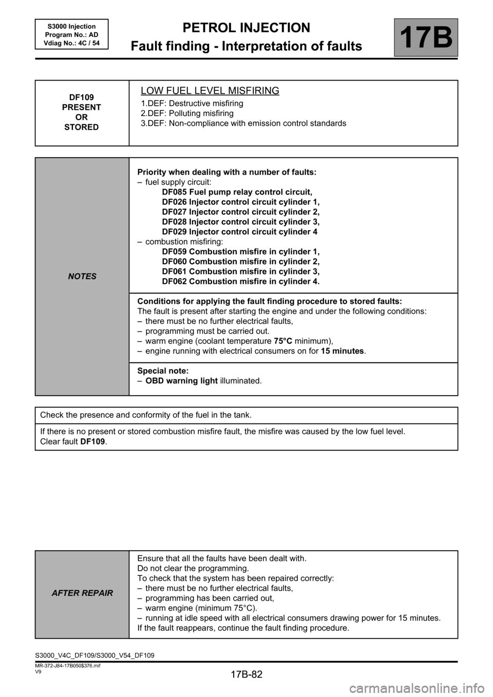
DF109
PRESENT
OR
STOREDLOW FUEL LEVEL MISFIRING
1.DEF: Destructive misfiring
2.DEF: Polluting misfiring
3.DEF: Non-compliance with emission control standards
NOTESPriority when dealing with a number of faults:
– fuel supply circuit:
DF085 Fuel pump relay control circuit,
DF026 Injector control circuit cylinder 1,
DF027 Injector control circuit cylinder 2,
DF028 Injector control circuit cylinder 3,
DF029 Injector control circuit cylinder 4
– combustion misfiring:
DF059 Combustion misfire in cylinder 1,
DF060 Combustion misfire in cylinder 2,
DF061 Combustion misfire in cylinder 3,
DF062 Combustion misfire in cylinder 4.
Conditions for applying the fault finding procedure to stored faults:
The fault is present after starting the engine and under the following conditions:
– there must be no further electrical faults,
– programming must be carried out.
– warm engine (coolant temperature 75°C minimum),
– engine running with electrical consumers on for 15 minutes.
Special note:
–OBD warning light illuminated.
Check the presence and conformity of the fuel in the tank.
If there is no present or stored combustion misfire fault, the misfire was caused by the low fuel level.
Clear fault DF109.
AFTER REPAIREnsure that all the faults have been dealt with.
Do not clear the programming.
To check that the system has been repaired correctly:
– there must be no further electrical faults,
– programming has been carried out,
– warm engine (minimum 75°C).
– running at idle speed with all electrical consumers drawing power for 15 minutes.
If the fault reappears, continue the fault finding procedure.
S3000_V4C_DF109/S3000_V54_DF109
Page 88 of 230
PETROL INJECTION
Fault finding - Interpretation of faults
17B
17B-88
PETROL INJECTION
Fault finding - Interpretation of faults
17B
17B-88V9 MR-372-J84-17B050$376.mif
S3000 Injection
Program No.: AD
Vdiag No.: 4C / 54
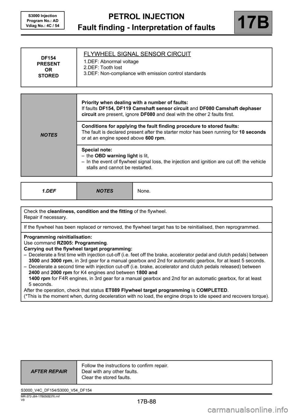
DF154
PRESENT
OR
STOREDFLYWHEEL SIGNAL SENSOR CIRCUIT
1.DEF: Abnormal voltage
2.DEF: Tooth lost
3.DEF: Non-compliance with emission control standards
NOTESPriority when dealing with a number of faults:
If faults DF154, DF119 Camshaft sensor circuit and DF080 Camshaft dephaser
circuit are present, ignore DF080 and deal with the other 2 faults first.
Conditions for applying the fault finding procedure to stored faults:
The fault is declared present after the starter motor has been running for 10 seconds
or at an engine speed above 600 rpm.
Special note:
–the OBD warning light is lit,
– In the event of flywheel signal loss, the injection and ignition are cut off: the vehicle
stalls and cannot be restarted.
1.DEF
NOTESNone.
Check the cleanliness, condition and the fitting of the flywheel.
Repair if necessary.
If the flywheel has been replaced or removed, the flywheel target has to be reinitialised, then reprogrammed.
Programming reinitialisation:
Use command RZ005: Programming.
Carrying out the flywheel target programming:
– Decelerate a first time with injection cut-off (i.e. feet off the brake, accelerator pedal and clutch pedals) between
3500 and 3000 rpm, in 3rd gear for a manual gearbox and 2nd for automatic gearbox, for at least 5 seconds.
– Decelerate a second time with injection cut-off (i.e. brake, accelerator and clutch pedals released) between
2400and 2000 rpm for K4 engines and between 1800 and
1400 rpm for F4R engines, in 3rd gear for a manual gearbox and 2nd for an automatic gearbox, for at least
5 seconds.
After the operation, check that status ET089 Flywheel target programming is COMPLETED.
(*This is the moment when, during deceleration with no load, the engine drops to idle speed and recovers torque).
AFTER REPAIRFollow the instructions to confirm repair.
Deal with any other faults.
Clear the stored faults.
S3000_V4C_DF154/S3000_V54_DF154
Page 90 of 230
PETROL INJECTION
Fault finding - Interpretation of faults
17B
17B-90
PETROL INJECTION
Fault finding - Interpretation of faults
17B
17B-90V9 MR-372-J84-17B050$376.mif
S3000 Injection
Program No.: AD
Vdiag No.: 4C / 54
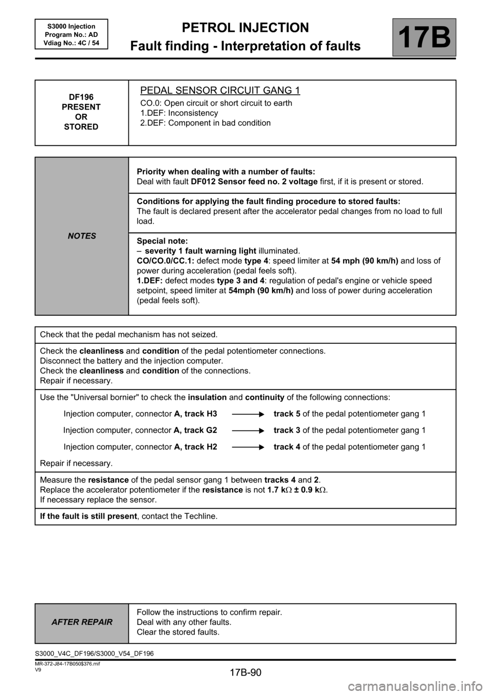
DF196
PRESENT
OR
STOREDPEDAL SENSOR CIRCUIT GANG 1
CO.0: Open circuit or short circuit to earth
1.DEF: Inconsistency
2.DEF: Component in bad condition
NOTESPriority when dealing with a number of faults:
Deal with fault DF012 Sensor feed no. 2 voltage first, if it is present or stored.
Conditions for applying the fault finding procedure to stored faults:
The fault is declared present after the accelerator pedal changes from no load to full
load.
Special note:
–severity 1 fault warning light illuminated.
CO/CO.0/CC.1: defect mode type 4: speed limiter at 54 mph (90 km/h) and loss of
power during acceleration (pedal feels soft).
1.DEF: defect modes type 3 and 4: regulation of pedal's engine or vehicle speed
setpoint, speed limiter at 54mph (90 km/h) and loss of power during acceleration
(pedal feels soft).
Check that the pedal mechanism has not seized.
Check the cleanliness and condition of the pedal potentiometer connections.
Disconnect the battery and the injection computer.
Check the cleanliness and condition of the connections.
Repair if necessary.
Use the "Universal bornier" to check the insulation and continuity of the following connections:
Injection computer, connectorA, track H3 track 5 of the pedal potentiometer gang 1
Injection computer, connectorA, track G2 track 3 of the pedal potentiometer gang 1
Injection computer, connectorA, track H2 track 4 of the pedal potentiometer gang 1
Repair if necessary.
Measure the resistance of the pedal sensor gang 1 between tracks 4 and 2.
Replace the accelerator potentiometer if the resistance is not 1.7 kΩ ± 0.9 kΩ.
If necessary replace the sensor.
If the fault is still present, contact the Techline.
AFTER REPAIRFollow the instructions to confirm repair.
Deal with any other faults.
Clear the stored faults.
S3000_V4C_DF196/S3000_V54_DF196
Page 91 of 230

PETROL INJECTION
Fault finding - Interpretation of faults
17B
17B-91
PETROL INJECTION
Fault finding - Interpretation of faults
17B
17B-91V9 MR-372-J84-17B050$376.mif
S3000 Injection
Program No.: AD
Vdiag No.: 4C / 54
DF198
PRESENT
OR
STOREDPEDAL SENSOR CIRCUIT GANG 2
CO.0: Open circuit or short circuit to earth
CC.1: Short-circuit to + 12 V
NOTESPriority when dealing with a number of faults:
Deal with fault DF011 Sensor supply voltage no. 1 first if it is present or stored.
Conditions for applying the fault finding procedure to stored faults:
The fault is declared present after the accelerator pedal changes from no load to full
load.
Special note:
–level 1 or 2 fault warning light lit,
– defect mode types 3 and 4: regulation of pedal's engine or vehicle speed setpoint,
speed limiter at 54mph (90 km/h) and loss of power during acceleration (pedal feels
soft).
Check that the pedal mechanism has not seized.
Check the cleanliness and condition of the pedal potentiometer connections.
Disconnect the battery and the injection computer.
Check the cleanliness and condition of the connections.
Repair if necessary.
Use the "Universal bornier" to check the insulation and continuity of the following connections:
Injection computer, connectorA, track F4 track 6 of the pedal potentiometer gang 2
Injection computer, connectorA, track F2 track 2 of the pedal potentiometer gang 2
Injection computer, connectorA, track F3 track 1 of the pedal potentiometer gang 2
Repair if necessary.
Measure the pedal sensor resistance gang 2 between tracks 6 and 1.
Replace the accelerator potentiometer if the resistance is not 2.8 kΩ±2.05kΩ.
If necessary replace the sensor.
If the fault is still present, contact the Techline.
AFTER REPAIRFollow the instructions to confirm repair.
Deal with any other faults.
Clear the stored faults.
S3000_V4C_DF198/S3000_V54_DF198
Page 94 of 230
PETROL INJECTION
Fault finding - Interpretation of faults
17B
17B-94
PETROL INJECTION
Fault finding - Interpretation of faults
17B
17B-94V9 MR-372-J84-17B050$423.mif
S3000 Injection
Program No.: AD
Vdiag No.: 4C / 54PETROL INJECTION
Fault finding - Interpretation of faults
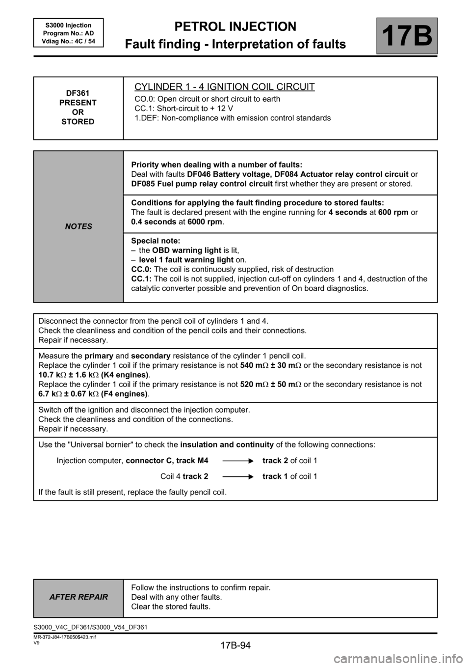
DF361
PRESENT
OR
STOREDCYLINDER 1 - 4 IGNITION COIL CIRCUIT
CO.0: Open circuit or short circuit to earth
CC.1: Short-circuit to + 12 V
1.DEF: Non-compliance with emission control standards
NOTESPriority when dealing with a number of faults:
Deal with faults DF046 Battery voltage, DF084 Actuator relay control circuit or
DF085 Fuel pump relay control circuit first whether they are present or stored.
Conditions for applying the fault finding procedure to stored faults:
The fault is declared present with the engine running for 4 seconds at 600 rpm or
0.4 seconds at 6000 rpm.
Special note:
–the OBD warning light is lit,
–level 1 fault warning light on.
CC.0: The coil is continuously supplied, risk of destruction
CC.1: The coil is not supplied, injection cut-off on cylinders 1 and 4, destruction of the
catalytic converter possible and prevention of On board diagnostics.
Disconnect the connector from the pencil coil of cylinders 1 and 4.
Check the cleanliness and condition of the pencil coils and their connections.
Repair if necessary.
Measure the primary and secondary resistance of the cylinder 1 pencil coil.
Replace the cylinder 1 coil if the primary resistance is not 540 mΩ ±30mΩ or the secondary resistance is not
10.7 kΩ ± 1.6 kΩ (K4 engines).
Replace the cylinder 1 coil if the primary resistance is not 520 mΩ ±50mΩ or the secondary resistance is not
6.7 kΩ ± 0.67 kΩ (F4 engines).
Switch off the ignition and disconnect the injection computer.
Check the cleanliness and condition of the connections.
Repair if necessary.
Use the "Universal bornier" to check the insulation and continuity of the following connections:
Injection computer, connector C, track M4 track 2 of coil 1
Coil 4 track 2 track 1 of coil 1
If the fault is still present, replace the faulty pencil coil.
AFTER REPAIRFollow the instructions to confirm repair.
Deal with any other faults.
Clear the stored faults.
S3000_V4C_DF361/S3000_V54_DF361
MR-372-J84-17B050$423.mif