ESP RENAULT SCENIC 2010 J95 / 3.G Petrol Injection S3000 Injection Service Manual
[x] Cancel search | Manufacturer: RENAULT, Model Year: 2010, Model line: SCENIC, Model: RENAULT SCENIC 2010 J95 / 3.GPages: 230, PDF Size: 0.92 MB
Page 93 of 230
PETROL INJECTION
Fault finding - Interpretation of faults
17B
17B-93
PETROL INJECTION
Fault finding - Interpretation of faults
17B
17B-93V9 MR-372-J84-17B050$376.mif
S3000 Injection
Program No.: AD
Vdiag No.: 4C / 54
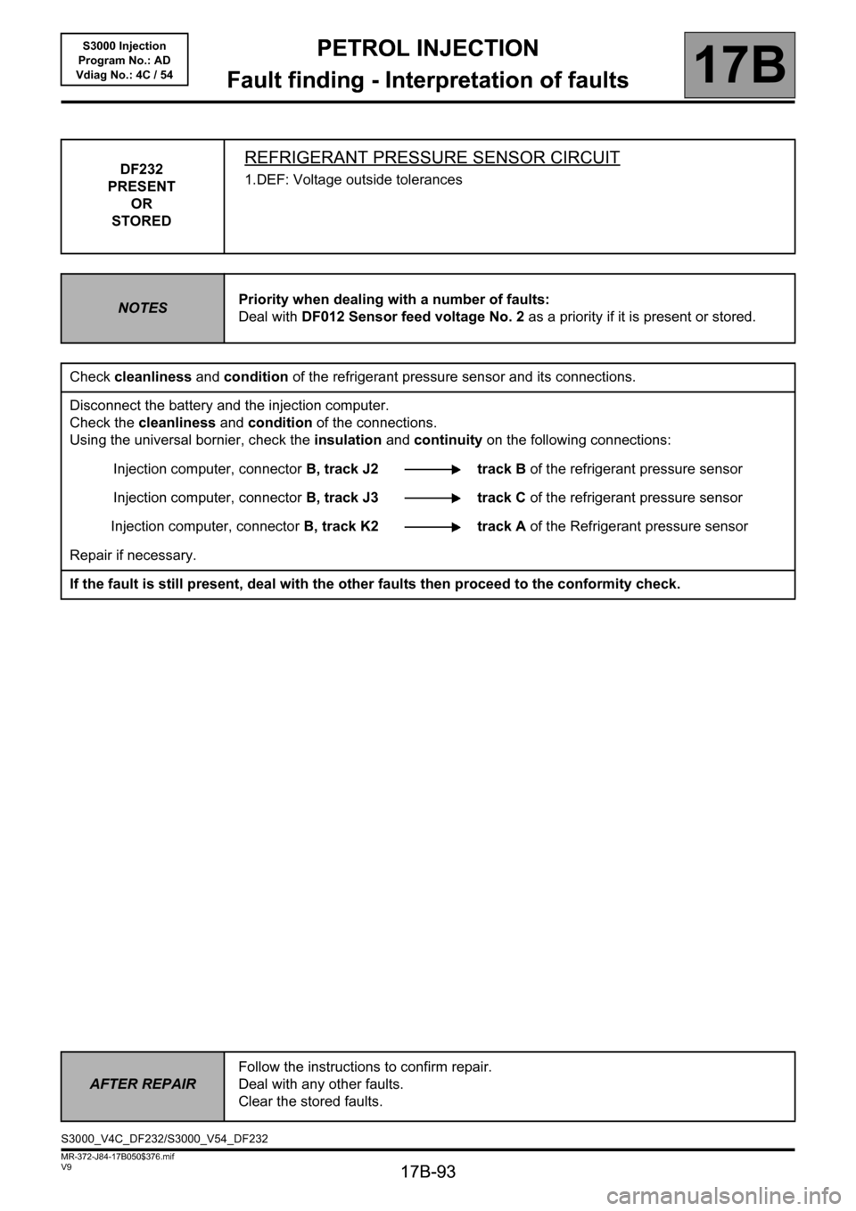
DF232
PRESENT
OR
STOREDREFRIGERANT PRESSURE SENSOR CIRCUIT
1.DEF: Voltage outside tolerances
NOTESPriority when dealing with a number of faults:
Deal with DF012 Sensor feed voltage No. 2 as a priority if it is present or stored.
Check cleanliness and condition of the refrigerant pressure sensor and its connections.
Disconnect the battery and the injection computer.
Check the cleanliness and condition of the connections.
Using the universal bornier, check the insulation and continuity on the following connections:
Injection computer, connectorB, track J2 track B of the refrigerant pressure sensor
Injection computer, connectorB, track J3 track C of the refrigerant pressure sensor
Injection computer, connectorB, track K2 track A of the Refrigerant pressure sensor
Repair if necessary.
If the fault is still present, deal with the other faults then proceed to the conformity check.
AFTER REPAIRFollow the instructions to confirm repair.
Deal with any other faults.
Clear the stored faults.
S3000_V4C_DF232/S3000_V54_DF232
Page 94 of 230
PETROL INJECTION
Fault finding - Interpretation of faults
17B
17B-94
PETROL INJECTION
Fault finding - Interpretation of faults
17B
17B-94V9 MR-372-J84-17B050$423.mif
S3000 Injection
Program No.: AD
Vdiag No.: 4C / 54PETROL INJECTION
Fault finding - Interpretation of faults
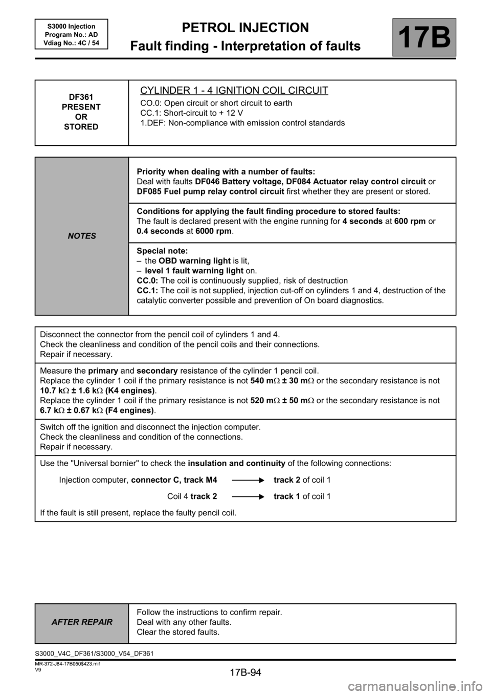
DF361
PRESENT
OR
STOREDCYLINDER 1 - 4 IGNITION COIL CIRCUIT
CO.0: Open circuit or short circuit to earth
CC.1: Short-circuit to + 12 V
1.DEF: Non-compliance with emission control standards
NOTESPriority when dealing with a number of faults:
Deal with faults DF046 Battery voltage, DF084 Actuator relay control circuit or
DF085 Fuel pump relay control circuit first whether they are present or stored.
Conditions for applying the fault finding procedure to stored faults:
The fault is declared present with the engine running for 4 seconds at 600 rpm or
0.4 seconds at 6000 rpm.
Special note:
–the OBD warning light is lit,
–level 1 fault warning light on.
CC.0: The coil is continuously supplied, risk of destruction
CC.1: The coil is not supplied, injection cut-off on cylinders 1 and 4, destruction of the
catalytic converter possible and prevention of On board diagnostics.
Disconnect the connector from the pencil coil of cylinders 1 and 4.
Check the cleanliness and condition of the pencil coils and their connections.
Repair if necessary.
Measure the primary and secondary resistance of the cylinder 1 pencil coil.
Replace the cylinder 1 coil if the primary resistance is not 540 mΩ ±30mΩ or the secondary resistance is not
10.7 kΩ ± 1.6 kΩ (K4 engines).
Replace the cylinder 1 coil if the primary resistance is not 520 mΩ ±50mΩ or the secondary resistance is not
6.7 kΩ ± 0.67 kΩ (F4 engines).
Switch off the ignition and disconnect the injection computer.
Check the cleanliness and condition of the connections.
Repair if necessary.
Use the "Universal bornier" to check the insulation and continuity of the following connections:
Injection computer, connector C, track M4 track 2 of coil 1
Coil 4 track 2 track 1 of coil 1
If the fault is still present, replace the faulty pencil coil.
AFTER REPAIRFollow the instructions to confirm repair.
Deal with any other faults.
Clear the stored faults.
S3000_V4C_DF361/S3000_V54_DF361
MR-372-J84-17B050$423.mif
Page 96 of 230
PETROL INJECTION
Fault finding - Interpretation of faults
17B
17B-96
PETROL INJECTION
Fault finding - Interpretation of faults
17B
17B-96V9 MR-372-J84-17B050$423.mif
S3000 Injection
Program No.: AD
Vdiag No.: 4C / 54
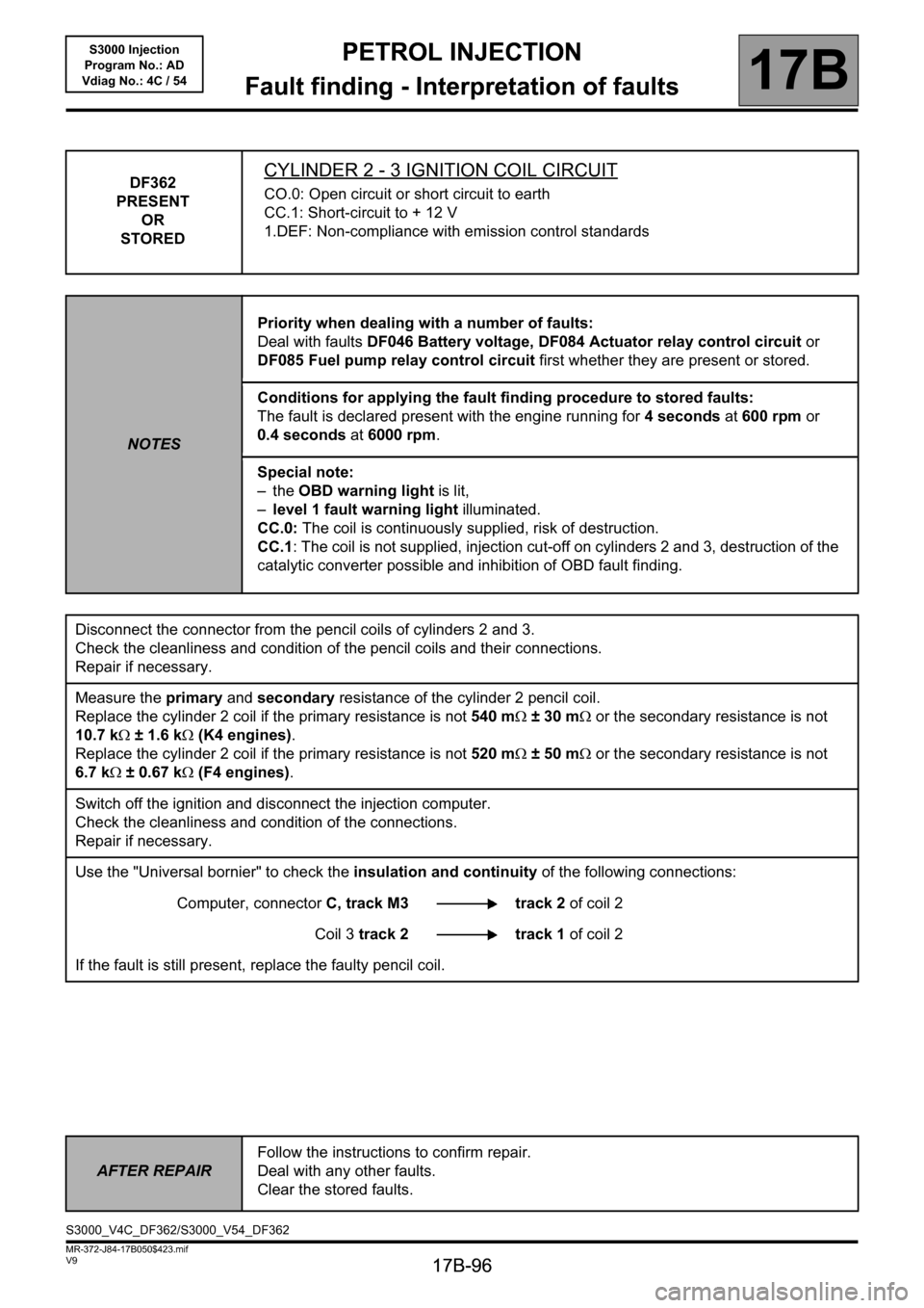
DF362
PRESENT
OR
STOREDCYLINDER 2 - 3 IGNITION COIL CIRCUIT
CO.0: Open circuit or short circuit to earth
CC.1: Short-circuit to + 12 V
1.DEF: Non-compliance with emission control standards
NOTESPriority when dealing with a number of faults:
Deal with faults DF046 Battery voltage, DF084 Actuator relay control circuit or
DF085 Fuel pump relay control circuit first whether they are present or stored.
Conditions for applying the fault finding procedure to stored faults:
The fault is declared present with the engine running for 4 seconds at 600 rpm or
0.4 seconds at 6000 rpm.
Special note:
–the OBD warning light is lit,
–level 1 fault warning light illuminated.
CC.0: The coil is continuously supplied, risk of destruction.
CC.1: The coil is not supplied, injection cut-off on cylinders 2 and 3, destruction of the
catalytic converter possible and inhibition of OBD fault finding.
Disconnect the connector from the pencil coils of cylinders 2 and 3.
Check the cleanliness and condition of the pencil coils and their connections.
Repair if necessary.
Measure the primary and secondary resistance of the cylinder 2 pencil coil.
Replace the cylinder 2 coil if the primary resistance is not 540 mΩ ±30mΩ or the secondary resistance is not
10.7 kΩ ± 1.6 kΩ (K4 engines).
Replace the cylinder 2 coil if the primary resistance is not 520 mΩ ±50mΩ or the secondary resistance is not
6.7 kΩ ± 0.67 kΩ (F4 engines).
Switch off the ignition and disconnect the injection computer.
Check the cleanliness and condition of the connections.
Repair if necessary.
Use the "Universal bornier" to check the insulation and continuity of the following connections:
Computer, connectorC, track M3 track 2 of coil 2
Coil 3 track 2 track 1 of coil 2
If the fault is still present, replace the faulty pencil coil.
AFTER REPAIRFollow the instructions to confirm repair.
Deal with any other faults.
Clear the stored faults.
S3000_V4C_DF362/S3000_V54_DF362
Page 98 of 230
PETROL INJECTION
Fault finding - Interpretation of faults
17B
17B-98
PETROL INJECTION
Fault finding - Interpretation of faults
17B
17B-98V9 MR-372-J84-17B050$423.mif
S3000 Injection
Program No.: AD
Vdiag No.: 4C / 54
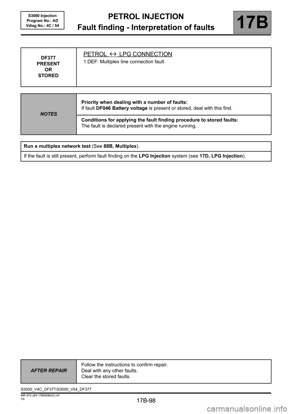
DF377
PRESENT
OR
STOREDPETROL LPG CONNECTION
1.DEF: Multiplex line connection fault
NOTESPriority when dealing with a number of faults:
If fault DF046 Battery voltage is present or stored, deal with this first.
Conditions for applying the fault finding procedure to stored faults:
The fault is declared present with the engine running.
Run a multiplex network test (See88B, Multiplex).
If the fault is still present, perform fault finding on the LPG Injection system (see17D, LPG Injection).
AFTER REPAIRFollow the instructions to confirm repair.
Deal with any other faults.
Clear the stored faults.
S3000_V4C_DF377/S3000_V54_DF377
Page 99 of 230
PETROL INJECTION
Fault finding - Interpretation of faults
17B
17B-99
PETROL INJECTION
Fault finding - Interpretation of faults
17B
17B-99V9 MR-372-J84-17B050$423.mif
S3000 Injection
Program No.: AD
Vdiag No.: 4C / 54
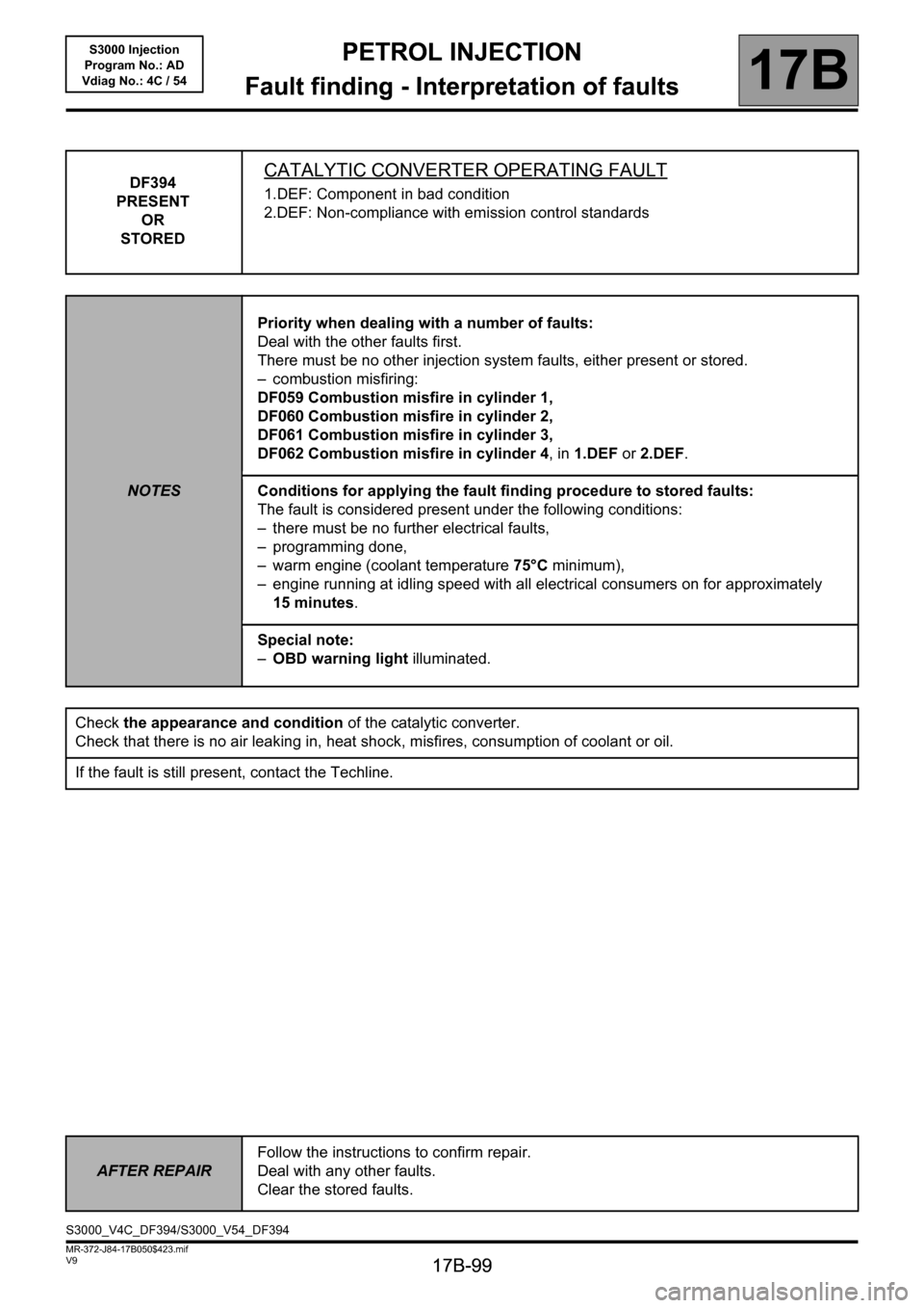
DF394
PRESENT
OR
STOREDCATALYTIC CONVERTER OPERATING FAULT
1.DEF: Component in bad condition
2.DEF: Non-compliance with emission control standards
NOTESPriority when dealing with a number of faults:
Deal with the other faults first.
There must be no other injection system faults, either present or stored.
– combustion misfiring:
DF059 Combustion misfire in cylinder 1,
DF060 Combustion misfire in cylinder 2,
DF061 Combustion misfire in cylinder 3,
DF062 Combustion misfire in cylinder 4, in 1.DEF or 2.DEF.
Conditions for applying the fault finding procedure to stored faults:
The fault is considered present under the following conditions:
– there must be no further electrical faults,
– programming done,
– warm engine (coolant temperature 75°C minimum),
– engine running at idling speed with all electrical consumers on for approximately
15 minutes.
Special note:
–OBD warning light illuminated.
Check the appearance and condition of the catalytic converter.
Check that there is no air leaking in, heat shock, misfires, consumption of coolant or oil.
If the fault is still present, contact the Techline.
AFTER REPAIRFollow the instructions to confirm repair.
Deal with any other faults.
Clear the stored faults.
S3000_V4C_DF394/S3000_V54_DF394
Page 100 of 230
PETROL INJECTION
Fault finding - Interpretation of faults
17B
17B-100
PETROL INJECTION
Fault finding - Interpretation of faults
17B
17B-100V9 MR-372-J84-17B050$423.mif
S3000 Injection
Program No.: AD
Vdiag No.: 4C / 54
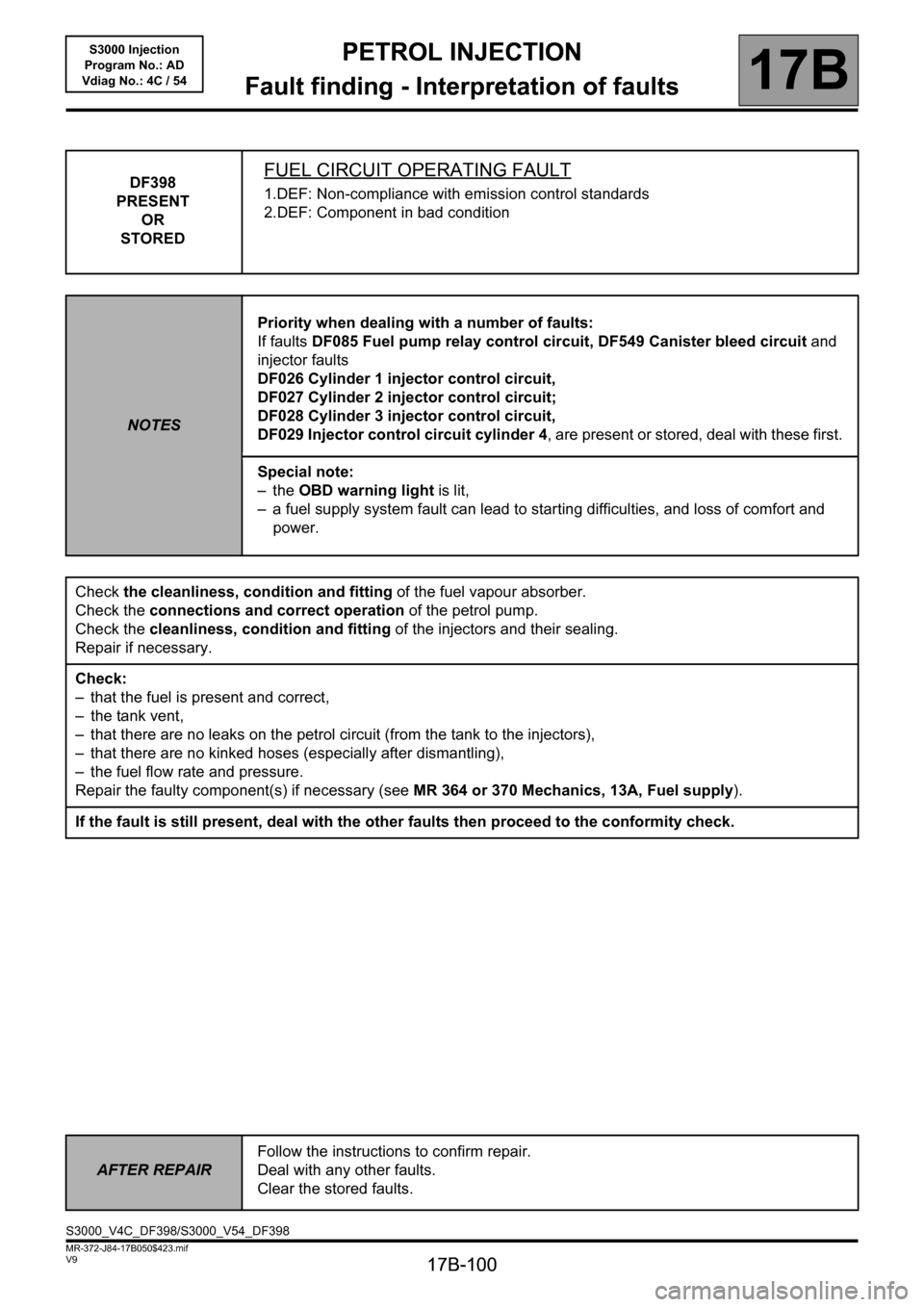
DF398
PRESENT
OR
STOREDFUEL CIRCUIT OPERATING FAULT
1.DEF: Non-compliance with emission control standards
2.DEF: Component in bad condition
NOTESPriority when dealing with a number of faults:
If faults DF085 Fuel pump relay control circuit, DF549 Canister bleed circuit and
injector faults
DF026 Cylinder 1 injector control circuit,
DF027 Cylinder 2 injector control circuit;
DF028 Cylinder 3 injector control circuit,
DF029 Injector control circuit cylinder 4, are present or stored, deal with these first.
Special note:
–the OBD warning light is lit,
– a fuel supply system fault can lead to starting difficulties, and loss of comfort and
power.
Check the cleanliness, condition and fitting of the fuel vapour absorber.
Check the connections and correct operation of the petrol pump.
Check the cleanliness, condition and fitting of the injectors and their sealing.
Repair if necessary.
Check:
– that the fuel is present and correct,
– the tank vent,
– that there are no leaks on the petrol circuit (from the tank to the injectors),
– that there are no kinked hoses (especially after dismantling),
– the fuel flow rate and pressure.
Repair the faulty component(s) if necessary (see MR 364 or 370 Mechanics, 13A, Fuel supply).
If the fault is still present, deal with the other faults then proceed to the conformity check.
AFTER REPAIRFollow the instructions to confirm repair.
Deal with any other faults.
Clear the stored faults.
S3000_V4C_DF398/S3000_V54_DF398
Page 101 of 230
PETROL INJECTION
Fault finding - Interpretation of faults
17B
17B-101
PETROL INJECTION
Fault finding - Interpretation of faults
17B
17B-101V9 MR-372-J84-17B050$423.mif
S3000 Injection
Program No.: AD
Vdiag No.: 4C / 54
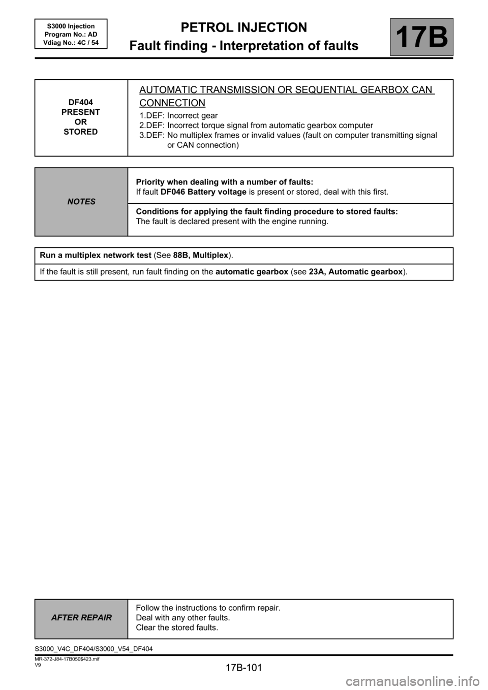
DF404
PRESENT
OR
STORED
AUTOMATIC TRANSMISSION OR SEQUENTIAL GEARBOX CAN
CONNECTION
1.DEF: Incorrect gear
2.DEF: Incorrect torque signal from automatic gearbox computer
3.DEF: No multiplex frames or invalid values (fault on computer transmitting signal
or CAN connection)
NOTESPriority when dealing with a number of faults:
If fault DF046 Battery voltage is present or stored, deal with this first.
Conditions for applying the fault finding procedure to stored faults:
The fault is declared present with the engine running.
Run a multiplex network test (See88B, Multiplex).
If the fault is still present, run fault finding on the automatic gearbox (see 23A, Automatic gearbox).
AFTER REPAIRFollow the instructions to confirm repair.
Deal with any other faults.
Clear the stored faults.
S3000_V4C_DF404/S3000_V54_DF404
Page 103 of 230
PETROL INJECTION
Fault finding - Interpretation of faults
17B
17B-103
PETROL INJECTION
Fault finding - Interpretation of faults
17B
17B-103V9 MR-372-J84-17B050$423.mif
S3000 Injection
Program No.: AD
Vdiag No.: 4C / 54
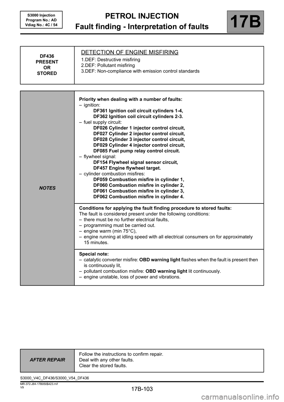
DF436
PRESENT
OR
STOREDDETECTION OF ENGINE MISFIRING
1.DEF: Destructive misfiring
2.DEF: Pollutant misfiring
3.DEF: Non-compliance with emission control standards
NOTESPriority when dealing with a number of faults:
– ignition:
DF361 Ignition coil circuit cylinders 1-4,
DF362 Ignition coil circuit cylinders 2-3.
– fuel supply circuit:
DF026 Cylinder 1 injector control circuit,
DF027 Cylinder 2 injector control circuit,
DF028 Cylinder 3 injector control circuit,
DF029 Cylinder 4 injector control circuit,
DF085 Fuel pump relay control circuit.
– flywheel signal:
DF154 Flywheel signal sensor circuit,
DF457 Engine flywheel target.
– cylinder combustion misfires:
DF059 Combustion misfire in cylinder 1,
DF060 Combustion misfire in cylinder 2,
DF061 Combustion misfire in cylinder 3,
DF062 Combustion misfire in cylinder 4.
Conditions for applying the fault finding procedure to stored faults:
The fault is considered present under the following conditions:
– there must be no further electrical faults,
– programming must be carried out.
– engine warm (min 75°C),
– engine running at idling speed with all electrical consumers on for approximately
15 minutes.
Special note:
– catalytic converter misfire: OBD warning light flashes when the fault is present then
is continuously lit,
– pollutant combustion misfire: OBD warning light lit continuously.
– engine unstable, loss of power and vibrations.
AFTER REPAIRFollow the instructions to confirm repair.
Deal with any other faults.
Clear the stored faults.
S3000_V4C_DF436/S3000_V54_DF436
Page 108 of 230
PETROL INJECTION
Fault finding - Interpretation of faults
17B
17B-108
PETROL INJECTION
Fault finding - Interpretation of faults
17B
17B-108V9 MR-372-J84-17B050$423.mif
S3000 Injection
Program No.: AD
Vdiag No.: 4C / 54
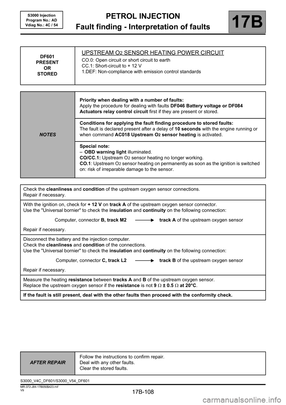
DF601
PRESENT
OR
STOREDUPSTREAM O2 SENSOR HEATING POWER CIRCUIT
CO.0: Open circuit or short circuit to earth
CC.1: Short-circuit to + 12 V
1.DEF: Non-compliance with emission control standards
NOTESPriority when dealing with a number of faults:
Apply the procedure for dealing with faults DF046 Battery voltage or DF084
Actuators relay control circuit first if they are present or stored.
Conditions for applying the fault finding procedure to stored faults:
The fault is declared present after a delay of 10 seconds with the engine running or
when command AC018 Upstream O2 sensor heating is activated.
Special note:
–OBD warning light illuminated.
CO/CC.1: Upstream O
2 sensor heating no longer working.
CO.1: Upstream O
2 sensor heating on permanently as soon as the ignition is switched
on: risk of irreparable damage to the sensor.
Check the cleanliness and condition of the upstream oxygen sensor connections.
Repair if necessary.
With the ignition on, check for + 12 V on track A of the upstream oxygen sensor connector.
Use the "Universal bornier" to check the insulation and continuity on the following connection:
Computer, connectorB, track M2 track A of the upstream oxygen sensor
Repair if necessary.
Disconnect the battery and the injection computer.
Check the cleanliness and condition of the connections.
Use the "Universal bornier" to check the insulation and continuity on the following connection:
Computer, connectorC, track L2 track B of the upstream oxygen sensor
Repair if necessary.
Measure the heating resistance between tracks A and B of the upstream oxygen sensor.
Replace the upstream oxygen sensor if the resistance is not 9Ω ± 0.5Ω at 20°C.
If the fault is still present, deal with the other faults then proceed with the conformity check.
AFTER REPAIRFollow the instructions to confirm repair.
Deal with any other faults.
Clear the stored faults.
S3000_V4C_DF601/S3000_V54_DF601
Page 109 of 230
PETROL INJECTION
Fault finding - Interpretation of faults
17B
17B-109
PETROL INJECTION
Fault finding - Interpretation of faults
17B
17B-109V9 MR-372-J84-17B050$423.mif
S3000 Injection
Program No.: AD
Vdiag No.: 4C / 54
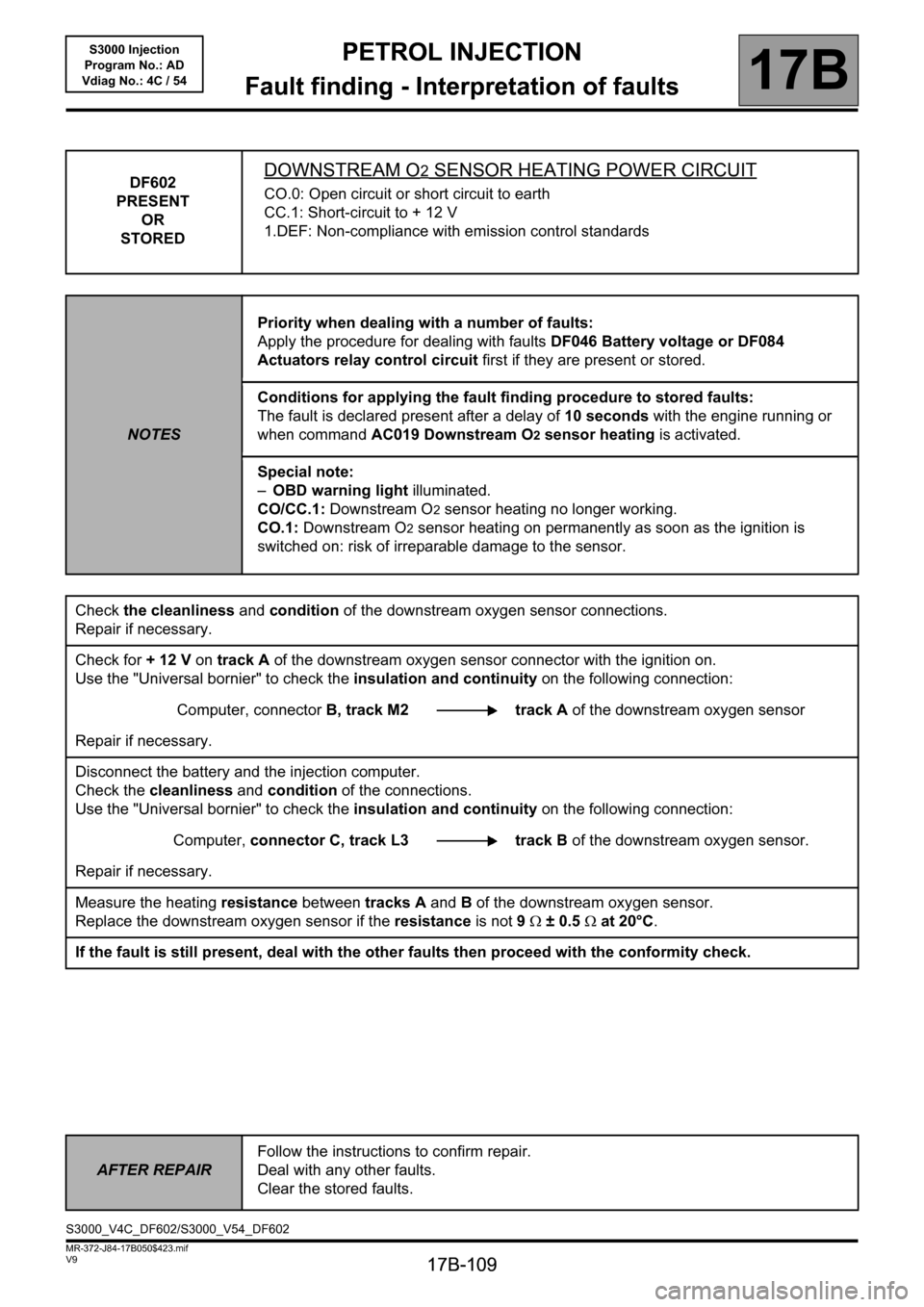
DF602
PRESENT
OR
STOREDDOWNSTREAM O2 SENSOR HEATING POWER CIRCUIT
CO.0: Open circuit or short circuit to earth
CC.1: Short-circuit to + 12 V
1.DEF: Non-compliance with emission control standards
NOTESPriority when dealing with a number of faults:
Apply the procedure for dealing with faults DF046 Battery voltage or DF084
Actuators relay control circuit first if they are present or stored.
Conditions for applying the fault finding procedure to stored faults:
The fault is declared present after a delay of 10 seconds with the engine running or
when command AC019 Downstream O2 sensor heating is activated.
Special note:
–OBD warning light illuminated.
CO/CC.1: Downstream O
2 sensor heating no longer working.
CO.1: Downstream O
2 sensor heating on permanently as soon as the ignition is
switched on: risk of irreparable damage to the sensor.
Check the cleanliness and condition of the downstream oxygen sensor connections.
Repair if necessary.
Check for + 12 V on track A of the downstream oxygen sensor connector with the ignition on.
Use the "Universal bornier" to check the insulation and continuity on the following connection:
Computer, connectorB, track M2 track A of the downstream oxygen sensor
Repair if necessary.
Disconnect the battery and the injection computer.
Check the cleanliness and condition of the connections.
Use the "Universal bornier" to check the insulation and continuity on the following connection:
Computer, connector C, track L3 track Bof the downstream oxygen sensor.
Repair if necessary.
Measure the heating resistance between tracks A and B of the downstream oxygen sensor.
Replace the downstream oxygen sensor if the resistance is not 9Ω ± 0.5Ω at 20°C.
If the fault is still present, deal with the other faults then proceed with the conformity check.
AFTER REPAIRFollow the instructions to confirm repair.
Deal with any other faults.
Clear the stored faults.
S3000_V4C_DF602/S3000_V54_DF602